ESCRIPTION
The EX129 Ser es ncludes a full range of sta nless steel f xed camera stat ons spec f cally des gned for Hazardous Area
appl cat ons. The des gn of the hous ngs ensures the best protect on from external agents along w th easy nstallat on
and ma ntenance serv ce. EX129 f xed camera stat ons are equ pped w th the latest generat on zoom module day/n ght
and thermal mag ng cameras, but they are also ava lable for Customer's spec f ed cameras.
The EX129 Ser es un ts have been des gned and cert f ed to the ATEX D rect ve 2014/34/EU to the follow ng:
II 2 G Ex db op pr IIC T6 Gb -40°C ≤ Tamb ≤ +60°C
II 2 D Ex tb IIIC T85°C Db -40°C ≤ Tamb ≤ +60°C
II 2 G Ex db op pr IIB T5 Gb -40°C ≤ Tamb ≤ +75°C
II 2 D Ex tb IIIC T100°C Db -40°C ≤ Tamb ≤ +75°C
Th s product s des gned for use w th flammable gases and vapours covered by apparatus groups IIA, IIB and IIC w th
temperature classes T1 to T6 (env ronmental temperature up to 60°C), w th flammable gases and vapours covered by
apparatus groups IIA and IIB w th temperature classes T1 to T5 (env ronmental temperature up to 75°C) and w th
flammable dust covered by apparatus groups IIIA, IIIB and IIIC w th temperature T=85°C. The surface temperature class of
the dev ce was determ ned only w th amb ent a r temperature, w thout tak ng nto cons derat on d rect sunl ght. The IP
rat ng of the un t s IP66/IP67.
Th s product must only be nstalled by su tably tra ned personnel n accordance w th the relevant code of pract ce (e.g.
EN60079-14). These nstruct ons are ntended for the r sole use.
CAUTION: It s recommended to use proper cert f ed cable glands and connect on cables (suppl ed upon request).
MO ELS
EX129-XY Standalone camera hous ng
EX129WW-XY Standalone camera hous ng w th w per
EX129IR-XY Standalone camera hous ng w th IR german um w ndow
EX129IRS-XY Standalone camera hous ng w th IR sapph re w ndow
EX129IR-SW-XY Standalone camera hous ng w th IR german um w ndow w thout front guard
X s a var able character referred to the cable entry (X).
It can be A (for M25) or B (for M20), C (for rear flange w th up to four M25 entr es) or D (for rear flange w th up to four M20
entr es).
PRELIMINARY REMARKS
i
Pr or to nstallat on and operat on, read carefully all nstruct ons the n th s manual and heed all warn ngs.
Unpack th s equ pment and handle t carefully. If the package appears to be damaged, not fy the sh pper mmed ately.
Use the or g nal packag ng to transport the un t. D sconnect power supply before mov ng t. In case of return ng the
equ pment, the or g nal packag ng must be used.
Any change performed on the un t that s not prev ously approved by the manufacturer w ll vo d both the cert f cat on
and the warranty.
Try ng to manually force the w per w ll result n damag ng the dev ce and w ll vo d the warranty.
Fasteners used for the assembly shall be M5-08x12 grade A4-70.
WARNING: Hazardous mov ng parts: the dev ce s remotely controlled and may change pos t on at any t me.
When nstall ng, choose a place where mov ng parts could not h t anyone or any object, creat ng hazardous s tuat ons.
h
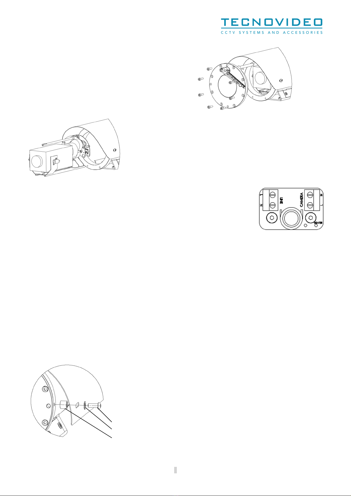
All the electr cal connect ons should be real zed n a non-explos ve atmosphere.
Earth ground attachment po nt s a stud M4-0.7 x16 A4-70 ISO 4762 w th dual nut and dual serrated washer. Dur ng
nstallat on t s mportant to connect t to an appropr ate ground ng locat on us ng a (m n mum) 10 AWG copper
stranded w re.
Before perform ng any operat on, turn off the power. The nstallat on of the un t can be performed only by qual f ed
personnel n accordance w th the relevant code of pract ce (e.g. EN60079-14) and w th all the relevant local and nat onal
standards nclud ng but not l m ted to the use of spec al p pes, tapes, sealants, cables and glands.
When leav ng the un t unused for long per ods, d sconnect supply cables.
For secur ty reasons, do not nstall the un t n the prox m ty of water conta ners and never push objects or pour l qu ds
nto the un t. The un t can be safely used n damp env ronments or outdoors, as long as the connectors are properly
sealed.
5