TECOM TS1061 User manual

TS1061
Dual Wiegand Interface
Installation Manual
P/N MAINST-TS1061 • REV 2.5 • ISS 16AUG19
Copyright
© 2019 UTC Fire & Security Australia Pty Ltd. All rights reserved.
Trademarks and
patents
The Challenger name and logo are trademarks of
UTC Fire & Security Australia Pty Ltd.
Other trade names used in this document may be trademarks or
registered trademarks of the manufacturers or vendors of the
respective products.
Manufacturer
Made in China by United Technologies Safety Systems
No. 80, Changjiang East Road, QETDZ, Qinhuangdao, Hebei,
P. R. China 066004
Imported by UTC Fire & Security Australia Pty Ltd t/a Interlogix
10 Ferntree Place,
Notting Hill, Victoria, 3168, Australia
ACMA compliance
Notice! This is a Class B product. In a domestic
environment this product may cause radio
interference in which case the user may be required
to take adequate measures.
WEEE compliance
For proper recycling, dispose all the batteries and the
packaging as required by local ordinances or
regulations
Contact information
For contact information, see www.interlogix.com.au.

TS1061 Dual Wiegand Interface Installation Manual i
Content
Important information................................................................... ii
Limitation of liability..........................................................................ii
Agency compliance..........................................................................ii
Contact information..........................................................................ii
Product overview.......................................................................... 1
Mechanical and environmental specifications................................. 1
Product contents............................................................................. 2
Related documentation................................................................... 2
Before you begin........................................................................... 3
Safety Warnings.............................................................................. 3
Installing the Dual Wiegand Interface ......................................... 4
Installation guidelines...................................................................... 4
Installation procedures.................................................................... 4
Mounting in the enclosure.................................................... 4
DIP switch settings.......................................................................... 5
Connections.................................................................................... 8
RS-485 LAN/Bus.................................................................. 9
Terminating the RS-485 LAN............................................. 11
Lock power......................................................................... 11
Door lock relay wiring......................................................... 12
Inputs ................................................................................. 12
Wiegand reader connections.............................................. 14
Door wiring example........................................................... 15
Earthing.............................................................................. 18
LED indications............................................................................. 19
Appendix A: Standalone current draw...................................... 20
Appendix B: User current draw................................................. 21
Appendix C: Operating temperature ......................................... 22
Appendix D: Cabling requirements........................................... 23
System earthing................................................................. 23
RS-485 cabling................................................................... 23
Power supply to RS-485 devices ....................................... 23

ii TS1061 Dual Wiegand Interface Installation Manual
Important information
Limitation of liability
To the maximum extent permitted by applicable law, in no event will Interlogix be
liable for any lost profits or business opportunities, loss of use, business
interruption, loss of data, or any other indirect, special, incidental, or
consequential damages under any theory of liability, whether based in contract,
tort, negligence, product liability, or otherwise. Because some jurisdictions do not
allow the exclusion or limitation of liability for consequential or incidental
damages the preceding limitation may not apply to you. In any event the total
liability of Interlogix shall not exceed the purchase price of the product. The
foregoing limitation will apply to the maximum extent permitted by applicable law,
regardless of whether Interlogix has been advised of the possibility of such
damages and regardless of whether any remedy fails of its essential purpose.
Installation in accordance with this manual, applicable codes, and the instructions
of the authority having jurisdiction is mandatory.
The customer is responsible for testing and determining the suitability of this
product for specific applications. The customer is responsible for testing the
product at least once every three months.
While every precaution has been taken during the preparation of this manual to
ensure the accuracy of its contents, Interlogix assumes no responsibility for
errors or omissions.
Agency compliance
This product conforms to the standards set by Standards Australia on behalf of
the Australian Communications and Media Authority (ACMA).
Ensure that enclosure covers are fitted to maintain ACMA compliance.
Notice! This is a Class B product. In a domestic environment this product may
cause radio interference in which case the user may be required to take
adequate measures.
Contact information
For contact information, see www.interlogix.com.au.

TS1061 Dual Wiegand Interface Installation Manual 1
Product overview
This manual applies to the TS1061 Dual Wiegand Interface. The Dual Wiegand
Interface can be attached to a ChallengerPlus panel or a TS1066 Network
Access Controller to provide two Wiegand interfaces, as well as additional inputs
and relays.
Note: The Dual Wiegand Interface is only compatible with ChallengerPlus and
not supported by Challenger10 or Challenger V8.
This manual describes:
•How to install the Dual Wiegand Interface
•How to connect the Dual Wiegand Interface to a ChallengerPlus panel or
a Network Access Controller
•How to connect other equipment to the Dual Wiegand Interface
This manual is intended for use only by trained Challenger installation and
configuration technicians.
Mechanical and environmental specifications
Storage
Temperature
-20 to +80°C
Location
Indoor. Dry area.
Physical dimensions
(W x D x H)
128 x 78 x 21 mm
Weight
255g
Operating environment
Temperature
0 to 50°C (Refer to Appendix C:
Operating temperature
Relative humidity
0 to 93% non-condensing
Pollution Class
2 or lower
Altitude
≤ 2000m

2 TS1061 Dual Wiegand Interface Installation Manual
Product contents
Inspect the package and contents for visible damage. If any components are
damaged or missing, do not use the unit; contact the supplier immediately. If you
need to return the unit, you must ship it in the original box.
Table 1 below lists the items that are shipped with a TS1061 Dual Wiegand
Interface.
Table 1: TS1061 shipping list
Quantity
Item
Quantity
Item
1
TS1061 board
7
2-way plug-on screw terminal
connectors
1
TS1061 Dual Wiegand Interface
Installation Manual
1
4-way RS-485 cable
5
M3 x 10 pan head screws
1
2-way lock power cable
4
Standoff board mounts
8
10K 1/4 watt resistors
8
3-way plug-on screw terminal
connectors
1
Earth lead
Related documentation
The ChallengerPlus Installation and Quick Programming Manual and
ChallengerPlus Programming Manual provide detailed information about
configuring and programming a ChallengerPlus system.
The ENC-LGE Large Enclosure Installation Manual provides instructions for
installing the ENC-LGE Large Enclosure.
The TS1066 Network Access Controller Installation Manual describes how to
install the TS1066 Network Access Controller. The TS1066 Network Access
Controller Programming Manual provides detailed information about configuring
and programming the Network Access Controller, including devices attached to
its buses, such as the TS1061 Dual Wiegand Interface.
The ChallengerPlus system is modular. Refer also to the documentation that is
shipped with each module that you intend to use.
TS1061 Dual Wiegand Interface Installation Manual 3
Before you begin
When installing a TS1061 Dual Wiegand Interface, or any other parts of the
system, you need to be aware of requirements for cabling and earthing, and plan
accordingly. Refer to “Appendix D: Cabling requirements” on page 23.
Notice! A qualified service person, complying with all applicable codes, should
perform all required hardware installation.
Disclaimer: This manual contains recommendations based on Australia and
New Zealand codes. It is not an authoritative reference regarding codes and has
not been reviewed by the responsible authorities. The codes may change and
may not be reflected in this document
Safety Warnings
Warning: Field wiring errors or damage may present hazardous voltages inside
the enclosure. Treat all wires and boards in the enclosure as hazardous until
checked and validated as safe.
Warning: Interlogix recommends the use of personal protection equipment, such
as gloves, glasses, voltage detectors and meters for all installation and
maintenance operations.
Warning: The fuses on the TS1061 Dual Wiegand Interface may be very hot if
they are in the tripped state or close to tripping. Do not touch.

4 TS1061 Dual Wiegand Interface Installation Manual
Installing the Dual Wiegand Interface
Installation guidelines
TS1061 Dual Wiegand Interfaces are designed, assembled and tested to comply
with the requirements related to safety, emission and immunity with respect to
environmental electrical and electromagnetic interference, as of current
applicable codes, when installed according to the requirements in this manual.
In addition to the general installation guidelines, installers must adhere to any
country dependent requirements of local applicable standards.
The TS1061 Dual Wiegand Interface is designed to be used with the
ChallengerPlus and Network Access Controller, and must be installed as
described in the Installation Manual of the panel it is connected to.
•Circuit separation, conduit materials, and workmanship are to comply with
all applicable codes and regulations.
•Only use units in a clean dry indoor environment, as described on page 1.
•Installation must be performed in accordance with AS/NZS 2201.
Installation procedures
The TS1061 Dual Wiegand Interface must be installed in the ENC-LGE Large
Enclosure.
Mounting in the enclosure
The installation procedure is as follows:
1. Install four standoff board mounts for the TS1061 board on the enclosure.
Refer to the ENC-LGE Large Enclosure Installation Manual for mounting
locations. Figure 9 on page 18 indicates some possible mounting locations in
the enclosure.
2. Remove the TS1061 board from its antistatic bag.
3. Use four M3 x 10 pan head screws to fix the board to the enclosure’s
standoffs.
4. Slide the board’s terminal connectors together and mount them to the board.
5. Configure the Interface’s address using the Address DIP switch. Refer to “DIP
switch settings” on page 5.

TS1061 Dual Wiegand Interface Installation Manual 5
DIP switch settings
The TS1061 Dual Wiegand Interface can be connected to a ChallengerPlus
panel’s COMMS 1 or COMMS 2, or a Network Access Controller’s BUS 1 or
BUS 2. The Interface is polled as a DGP. The addressing ranges that can be
used depend on whether the Interface is connected to a ChallengerPlus or a
Network Access Controller, as shown in Table 2 below.
Table 2: Interface addressing ranges
LAN/Bus
Address
Polled as
ChallengerPlus
COMMS 1
1 to 12
DGP 1 to 12
COMMS 2
1 to 12
DGP 17 to 28
Network Access Controller
BUS 1
1 to 15
DGP 1 to 15
BUS 2
1 to 16
DGP 17 to 32
Use the four-segment Address DIP switch to set the address.
Figure 1: Address DIP switch
Settings for connection to ChallengerPlus panel:
The DIP switch settings for connection to a ChallengerPlus panel are shown in
Table 3 below.
Table 3: DIP switch settings for connection to ChallengerPlus
ChallengerPlus LAN
Address
Polled
as
Door
numbers
S1-1
S1-2
S1-3
S1-4
COMMS 1
1
DGP 1
17, 18
I
O
O
O
COMMS 1
2
DGP 2
21, 22
O
I
O
O
COMMS 1
3
DGP 3
25, 26
I
I
O
O
COMMS 1
4
DGP 4
29, 30
O
O
I
O
COMMS 1
5
DGP 5
33, 34
I
O
I
O
COMMS 1
6
DGP 6
37, 38
O
I
I
O
COMMS 1
7
DGP 7
41, 42
I
I
I
O
COMMS 1
8
DGP 8
45, 46
O
O
O
I
COMMS 1
9
DGP 9
49, 50
I
O
O
I
COMMS 1
10
DGP 10
53, 54
O
I
O
I
COMMS 1
11
DGP 11
57, 58
I
I
O
I
COMMS 1
12
DGP 12
61, 62
O
O
I
I
COMMS 2
1
DGP 17
81, 82
I
O
O
O

6 TS1061 Dual Wiegand Interface Installation Manual
ChallengerPlus LAN
Address
Polled
as
Door
numbers
S1-1
S1-2
S1-3
S1-4
COMMS 2
2
DGP 18
85, 86
O
I
O
O
COMMS 2
3
DGP 19
89, 90
I
I
O
O
COMMS 2
4
DGP 20
93, 94
O
O
I
O
COMMS 2
5
DGP 21
97, 98
I
O
I
O
COMMS 2
6
DGP 22
101, 102
O
I
I
O
COMMS 2
7
DGP 23
105, 106
I
I
I
O
COMMS 2
8
DGP 24
109, 110
O
O
O
I
COMMS 2
9
DGP 25
113, 114
I
O
O
I
COMMS 2
10
DGP 26
117, 118
O
I
O
I
COMMS 2
11
DGP 27
121, 122
I
I
O
I
COMMS 2
12
DGP 28
125, 126
O
O
I
I
Legend: I=ON, O=OFF
Settings for connection to Network Access Controller:
The DIP switch settings for connection to a Network Access Controller are shown
in Table 4 below.
Table 4: DIP switch settings for connection to Network Access Controller
Network
Access
Controller
Bus
Address
Polled as
S1-1
S1-2
S1-3
S1-4
BUS 1
1
DGP 1
I
O
O
O
BUS 1
2
DGP 2
O
I
O
O
BUS 1
3
DGP 3
I
I
O
O
BUS 1
4
DGP 4
O
O
I
O
BUS 1
5
DGP 5
I
O
I
O
BUS 1
6
DGP 6
O
I
I
O
BUS 1
7
DGP 7
I
I
I
O
BUS 1
8
DGP 8
O
O
O
I
BUS 1
9
DGP 9
I
O
O
I
BUS 1
10
DGP 10
O
I
O
I
BUS 1
11
DGP 11
I
I
O
I
BUS 1
12
DGP 12
O
O
I
I
BUS 1
13
DGP 13
I
O
I
I
BUS 1
14
DGP 14
O
I
I
I
BUS 1
15
DGP 15
I
I
I
I
BUS 2
1
DGP 17
I
O
O
O

TS1061 Dual Wiegand Interface Installation Manual 7
Network
Access
Controller
Bus
Address
Polled as
S1-1
S1-2
S1-3
S1-4
BUS 2
2
DGP 18
O
I
O
O
BUS 2
3
DGP 19
I
I
O
O
BUS 2
4
DGP 20
O
O
I
O
BUS 2
5
DGP 21
I
O
I
O
BUS 2
6
DGP 22
O
I
I
O
BUS 2
7
DGP 23
I
I
I
O
BUS 2
8
DGP 24
O
O
O
I
BUS 2
9
DGP 25
I
O
O
I
BUS 2
10
DGP 26
O
I
O
I
BUS 2
11
DGP 27
I
I
O
I
BUS 2
12
DGP 28
O
O
I
I
BUS 2
13
DGP 29
I
O
I
I
BUS 2
14
DGP 30
O
I
I
I
BUS 2
15
DGP 31
I
I
I
I
BUS 2
16
DGP 32
O
O
O
O
Legend: I = ON, O = OFF
8 TS1061 Dual Wiegand Interface Installation Manual
Connections
See Figure 2 below for the locations of connectors and other items. See
“Appendix D: Cabling requirements” on page 23 for recommendations for the
application and wiring of Challenger equipment.
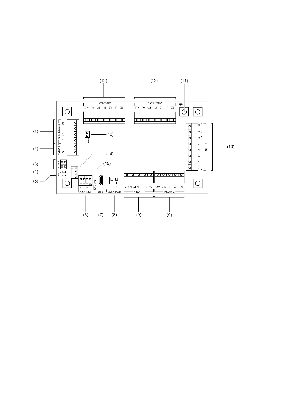
Figure 2: TS1061 board details
Figure 2 legend
Item
Description
1.
ChallengerPlus application: Connect the TECOM BUS +12, TECOM BUS −, TECOM
BUS D+ and TECOM BUS D−terminals to the ChallengerPlus panel’s COMMS 1 or
COMMS 2 cable.
Network Access Controller application: Connect the TECOM BUS +12, TECOM BUS
−, TECOM BUS D+ and TECOM BUS D−terminals to the Network Access Controller’s
BUS 1 or BUS 2 cable. (Only use if (14) is not used).
2.
Connect the TAMP T and TAMP C terminals to the panel tamper switch in the enclosure.
Short circuit for sealed, open circuit for unsealed. Must be sealed if not used. Can only be
used with normally closed contacts such as the panel tamper switches.
Note: Panel tamper switch must only be connected to one board in the enclosure.
3.
TEST 1 and TEST 2 links. Both links are used when updating firmware via CTPlus (refer
to “Upgrading firmware” in the CTPlus online help for instructions).
4.
COMMS Tx LED to indicate activity on the RS-485 LAN/bus. See “LED indications”on
page 19.
5.
COMMS Rx LED to indicate activity on the RS-485 LAN/bus. See “LED indications”on
page 19.

TS1061 Dual Wiegand Interface Installation Manual 9
Item
Description
6.
Address selection DIP switch. Configure the Interface’s address using the ADDRESS DIP
switch. Refer to “
DIP switch settings” on page 5.
7.
Micro-B USB port (USB cable not supplied).
8.
LOCK PWR 2-pin plug-in socket for lock power cable from a Network Access Controller.
9.
Relay connections for two doors. Refer to “
Door lock relay wiring” on page 12. A suppression diode (such as 1N4004) must be fitted
across door locks.
10.
Input terminals. See “Inputs” on page 12.
11.
Earth terminal. Attach the ring terminal of the supplied earth lead. See “
Earthing” on page 18.
12.
Two sets of Wiegand reader connections. See “Wiegand reader connections” on page
14.
13.
TERM link for the RS-485 LAN/bus. See “Terminating the RS-485 LAN” on page 11.
14.
4-pin plug-in socket for easy RS-485 cable connection to a Network Access Controller’s
BUS 1.
15.
Heart beat LED. See “LED indications”on page 19.
RS-485 LAN/Bus
The TS1061 Dual Wiegand Interface can be connected to a ChallengerPlus
panel or Network Access Controller via the 4-pin RS-485 terminals (Figure 2 on
page 8 item 1).
Alternatively, the Interface can be connected to a Network Access Controller’s
BUS 1 via the 4-pin plug-in RS-485 socket (Figure 2 on page 8 item 14).
Using the plug-in RS-485 socket:
To easily connect the Interface to a Network Access Controller’s BUS 1, connect
a 4-way RS-485 cable (supplied) to the 4-pin plug-in RS-485 socket (Figure 2 on
page 8 item 14).
Refer to Figure 3 on page 10 for example connections of the 4-way RS-485 cable
from a Network Access Controller to the Interface (items B and D).

10 TS1061 Dual Wiegand Interface Installation Manual
Figure 3: Example TS1066 to TS1061 cable connections for RS-485 and lock power
Note: Refer to the TS1066 Network Access Controller Installation Manual for
information on the maximum total current draw allowed from a Network Access
Controller.
Using the RS-485 terminals:
Use 2-pair twisted shielded data cable such as Belden 8723 to connect the
Interface to a ChallengerPlus panel or Network Access Controller.
•Connect the +12 terminal to the red wire. The +12 terminal provides +12 V
to the Interface (Refer to section Power supply to RS-485 devices for
more details).
•Connect the − terminal to the black wire.
•Connect the D+ terminal to the white wire. The D+ terminal is data
positive.
•Connect the D− terminal to the green wire. The D− terminal is data
negative.
•Connect the data cable shield to the LAN earth connection (Figure 2 on
page 8, item 11) if the other end of the data cable shield is not earthed.
TS1061
TS1061

TS1061 Dual Wiegand Interface Installation Manual 11
Terminating the RS-485 LAN
All Challenger LAN devices (including the panel) use a 470 Ω LAN termination
resistor where required. LAN termination resistors are used to set the impedance
of the LAN to around 220 Ω in order to minimise noise. The termination resistor
may be external or on-board (devices with an on-board resistor use a link to set
the LAN termination to ON).
A Challenger LAN should have only two devices with the LAN termination set to
ON (or the LAN termination resistor fitted):
•In a straight LAN configuration, the TERM links are ON at the Challenger
panel and the most distant device.
•In a star LAN configuration, the TERM links are ON at the two devices that
are the furthest apart (and OFF at the Challenger panel).
In a completely connected (but powered down) system, you can check for correct
LAN termination by measuring the resistance across the D+ and D− terminals:
•0 Ω indicates a short circuit in the cabling
•160 Ω or less indicates that too many devices are terminated
•220 Ω is good
•470 Ω or more indicates that not enough devices are terminated
Lock power
Additional power for locks can be supplied from a Network Access Controller via
the 2-pin plug-in lock power socket (Figure 2 on page 8, item 8). Connect a
2-way lock power cable (supplied) to the 2-pin plug-in lock power socket to
provide additional power for locks.
Refer to Figure 3 on page 10 for example connections of the 2-way lock power
cable from a Network Access Controller to the Interface (items A and C).
Note: Refer to the TS1066 Network Access Controller Installation Manual for
information on the maximum total current draw allowed from a Network Access
Controller.

12 TS1061 Dual Wiegand Interface Installation Manual
Door lock relay wiring
Figure 4 below details the wiring for the relay terminal blocks.
Figure 4: Door lock wiring options (relay shown de-energised)
Note: A suppression diode such as 1N4004 must be used in door lock circuits.
The diode must be co-located with the lock.
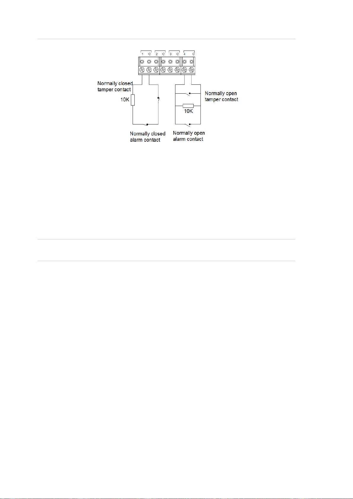
Inputs
Each pair of input terminals may be connected to a device such as a detector or
reed switch.
The ChallengerPlus panel or Network Access Controller can monitor its input
circuits for four states (sealed, unsealed, open circuit, and short circuit). This is
accomplished by using two end-of-line (EOL) resistors in each input circuit, as
shown in Figure 5 on page 13.
Note: ChallengerPlus panels and Network Access Controllers can have various
EOL resistor values for input tamper monitoring (the default is 10 kΩ resistors).
EOL resistor values for ChallengerPlus panels or NAC can be programmed using
CTPlus (Panel Programming -> Panel Options -> System Options ->Setup
menu).
EOL resistor values for Dual Weigand Interface can be different to
ChallengerPlus panel or Network Access Controller it is connected to and must
be set within the device using CTPlus or RAS install menu.

TS1061 Dual Wiegand Interface Installation Manual 13
Install EOL resistors in input circuits at the end of the circuit. If an alarm device is
connected, place the EOL resistors at the device’s connections. If an input is not
used, you do not need to connect an EOL resistor.
Tip: Use sleeves on the resistor leads to prevent accidental shorting.
Figure 5: Four-state monitored input circuits
When four-state monitoring is used, the panel uses the circuit’s resistance to
determine the state of the input. In this example, 10 kΩ EOL resistors have been
used:
•10 kΩ indicates sealed
•5 kΩ or 20 kΩ indicates unsealed
•Open circuit indicates input tamper
•Short circuit indicates input tamper
To use four-state monitoring, input tamper monitoring must be set to Yes for the
ChallengerPlus panel or Network Access Controller. See the ChallengerPlus
Programming Manual or the TS1066 Network Access Controller Programming
Manual, respectively, for information on enabling tamper monitoring.
Alternatively, the ChallengerPlus panel or Network Access Controller can be
configured to monitor inputs for two states (sealed and unsealed). This is
accomplished by using one resistor in each circuit, as shown in Figure 6 on page
14.
14 TS1061 Dual Wiegand Interface Installation Manual
Figure 6: Two-state monitored input circuits
The panel uses the circuit’s resistance to determine the state of the input. In this
example, 10 kΩ EOL resistors have been used:
•10 kΩ indicates sealed
•Open circuit or short circuit indicates unsealed
To use two-state monitoring, tamper monitoring must be disabled for the
ChallengerPlus panel or Network Access Controller. See the ChallengerPlus
Programming Manual or the TS1066 Network Access Controller Programming
Manual, respectively, for information on disabling tamper monitoring.
Note: Two-state monitoring is not compatible with input types 33 or 40. See the
ChallengerPlus Programming Manual for details.
Wiegand reader connections
The TS1061 Dual Wiegand Interface can have two Wiegand devices, such as
readers, connected to terminal blocks shown on Figure 2 on page 8, item 12.
Figure 7 on page 15 details typical Wiegand reader wiring.


16 TS1061 Dual Wiegand Interface Installation Manual
Figure 8 on page 17 consolidates the different connections of a TS1061 Dual
Wiegand Interface into one diagram. It shows an example of using the Interface
to connect to various parts of a door:
•The door’s contact is connected to the first input on the Interface
(Figure 2 on page 8, item 10)
•The door’s egress button, on the other side of the wall, is connected to the
second input on the Interface (Figure 2 on page 8, item 10)
•The door’s card reader is connected to the first set of Wiegand reader
connections (Figure 2 on page 8, item 12)
•The door’s lock is connected to the first relay on the Interface (Figure 2 on
page 8, item 9)
The figure shows references to other figures in this document that provide
additional wiring information.
The figure indicates that a second set of connections (relay, Wiegand reader,
and inputs) can be used for a second door.
The figure also indicates that the Interface is connected to a ChallengerPlus
panel or Network Access Controller.
Table of contents


