TeeJet AEROS9040 User manual

USER GUIDE
AEROS9040
Software version 4.31

Table of Contents
START SIMPLE GUIDANCE 1
#1 POWER ON 1
#2 HOME SCREEN 1
System Setup .................................................................................................................................................................1
RealView Camera Full Screen Video View......................................................................................................................1
ISOBUS Universal Terminal View ....................................................................................................................................1
Simple or Advanced Mode.........................................................................................................................................1
#3 GO TO CONFIGURATION 2
1) Set Up the Local Cultural Settings.......................................................................................................................................................2
2) Set Up the GNSS.........................................................................................................................................................................................2
3) Set Up the Implement..............................................................................................................................................................................3
Implement Settings per Equipment Present...............................................................................................................3
Single Section Setup ......................................................................................................................................................3
Section(s) with ISOBUS Sprayer/Spreader Setup...........................................................................................................4
Additional Settings per Implement Type ....................................................................................................................4
Section Numbers .............................................................................................................................................................5
Straight ............................................................................................................................................................................5
Spreader – TeeJet............................................................................................................................................................6
Lateral Implement Offset Distance Adjustment ..........................................................................................................7
GNSS Offset Adjustment Calculation...............................................................................................................................7
Lateral Implement Offset Adjustment...............................................................................................................................8
4) Set Up the Mapping Location ...............................................................................................................................................................9
#4 START NEW JOB OR CONTINUE JOB 10
Simple Mode ................................................................................................................................................................................................. 10
Advanced Mode........................................................................................................................................................................................... 10
#5 SET UP GUIDANCE 11
1) Choose a Guidance Mode.................................................................................................................................................................... 11
2) Establish an AB guideline .................................................................................................................................................................... 12
3) Create an Application Boundary....................................................................................................................................................... 12
ADD RATE CONTROL 14
Guidance Screen Options......................................................................................................................................................................... 14
MAPPING OPTIONS 15
Duplicating and Transferring Maps ................................................................................................................................15
Coverage Map............................................................................................................................................................................................... 16
Polygons Map ............................................................................................................................................................................................... 16
Prescription Map.......................................................................................................................................................................................... 16
Application and Target Rate Maps ........................................................................................................................................................ 17
Target Rates...................................................................................................................................................................17
Color Range Selection ............................................................................................................................................17
iii
98-01504-ENUS R2
Aeros 9040 Field Computer
INFORMATION ON GUIDANCE MODES 18
Vehicle View................................................................................................................................................................................................... 18
Field View........................................................................................................................................................................................................ 18
RealView Guidance ..................................................................................................................................................................................... 19
GUIDANCE MODES 19
Straight AB Guidance................................................................................................................................................................................. 19
Curved AB Guidance .................................................................................................................................................................................. 19
Adaptive Curve AB Guidance.................................................................................................................................................................. 19
Circle Pivot Guidance ................................................................................................................................................................................. 20
Last Pass Guidance...................................................................................................................................................................................... 20
NextRow Guidance ..................................................................................................................................................................................... 20
No Guidance.................................................................................................................................................................................................. 20
SCREENS OPTIONS 21
GUIDANCE BAR 25
STATUS BAR 26
GUIDANCE FEATURES DETAILS 27
A+ Nudge Feature....................................................................................................................................................................................... 27
Azimuth Degree........................................................................................................................................................................................... 27
Return to Point.............................................................................................................................................................................................. 28
Next Guideline Feature.............................................................................................................................................................................. 29
REFRESH GNSS POSITION 29
BOOMPILOT 30
No Section Control Module ..................................................................................................................................................................... 30
ISOBUS Sprayer............................................................................................................................................................................................. 30
ISOBUS Spreader.......................................................................................................................................................................................... 31
With TeeJet Section Control Module And Switchbox or ISM....................................................................................................... 32
With TeeJet Section Control Module .................................................................................................................................................... 32
ADDITIONAL IMPLEMENT OPTIONS 33
TIP SELECTION 33
Preset .....................................................................................................................................................................33
Tip Sizes and Associated Colors....................................................................................................................................33
Current Tip..............................................................................................................................................................34
DROPLET SIZE MONITOR 34
Setup................................................................................................................................................................................................................ 34
Enable/Disable DSM ...............................................................................................................................................34
Tip Selection / Current Tip.......................................................................................................................................34
Input/Output Module Pressure Sensor.....................................................................................................................34

iv www.teejet.com
Aeros 9040 Field Computer
Operation ....................................................................................................................................................................................................... 35
Status Bar...............................................................................................................................................................35
Droplet Size Chart..........................................................................................................................................................35
Guidance Bar ..........................................................................................................................................................35
REVERSE SENSE 36
BOOMPILOT SECTION CONTROL 37
TIP FLOW MONITOR 38
ISOBUS SPRAYER OFFSETS 38
Self-propelled ............................................................................................................................................................................................... 39
Three Point Hitch ......................................................................................................................................................................................... 39
Trailed .............................................................................................................................................................................................................. 40
DATA MANAGEMENT 41
Job Data .......................................................................................................................................................................................................... 42
Copy Job Data ...............................................................................................................................................................42
Machine Settings......................................................................................................................................................................................... 43
Copy Machine Prole.....................................................................................................................................................43
SYSTEM CONFIGURATIONS 44
Safety Information
TeeJet Technologies is not responsible for damage or physical harm caused by failure to adhere to the following safety requirements.
As the operator of the vehicle, you are responsible for its safe operation.
The Aeros 9040 in combination with any assisted/auto steering device is not designed to replace the vehicle’s operator.
Do not leave a vehicle while the Aeros 9040 is engaged.
Be sure that the area around the vehicle is clear of people and obstacles before and during engagement.
The Aeros 9040 is designed to support and improve efciency while working in the eld. The driver has full responsibility for the quality and work
related results.
Disengage or remove any assisted/auto steering device before operating on public roads.

1
98-01504-ENUS R2
Aeros 9040 Field Computer
START SIMPLE GUIDANCE
#1 POWER ON
Integrated RAM Mount
(assembly required)
Speed Digital (LAN)
Connection
with Rubber Cover
Camera Connection
with Rubber Cover
Power Connection
Speakers
GNSS Antenna Connection
WiFi Antenna Connection
USB Ports with Rubber
Covers
USB Ports with Rubber Covers
Bright Touch Screen
Power Button
Favorites Button
Home Button
Recommended Antenna Installation
The GNSS antenna should be mounted as far forward as possible on
top of the cab on a metal surface of at least 4 in × 4 in / 10 cm × 10 cm.
Home Button
The Home button provides a shortcut to the Home screen.
Power On/Off Button
On – Press the POWER button to power on the console. Upon
power up, the Aeros will begin its start up sequence.
Off – Press and briey hold the POWER button until a conrmation
screen acknowledges shut down mode.
WARNING! Wait 10 seconds before restarting the console.
#2 HOME SCREEN
Once the power up sequence has completed, the Home screen will
appear with the options to start a new job or continue an existing job.
Home/Job Screen (or press Home Button)
Unit Setup
RealView Camera Full Screen Video View
ISOBUS Universal Terminal
System Setup
System Setup is used to congure the console, the machine and its
implements. Four side tabs access options for Machine/Implement
Conguration, Data Management, Console Settings, and Tools.
RealView Camera Full Screen Video View
View video feed(s) and setup cameras without GNSS available.
Options for RealView Guidance are not available on this screen.
ISOBUS Universal Terminal View
Access to an ISOBUS Electronic Control Unit (ECU) options and
operation. This provides crop sprayer or spreader control when
integrated into the implement of either capability.
Simple or Advanced Mode
To change between simple mode and advanced mode, see the
conguration chapter under Data –> Options.
►Simple Mode – only one job will be available at a time. Only
bounded area and coverage areas are displayed on the home
screen. Only the current job is available for saving in Reports.
Use with Fieldware Link is not available.
►Advanced Mode – more than one job will be available at any
time. Client, farm, eld and job names; bounded and coverage
areas; application time; and distance from selected job are
displayed on the home screen. All saved job proles can be
exported as a PDF, SHP or KML le to a USB drive using
Data -> Reports.

2www.teejet.com
Aeros 9040 Field Computer
#3 GO TO CONFIGURATION
From the Home screen, select the System Setup bottom button to congure the console, the machine and its implements. Four side tabs access
options for Machine/Implement Conguration, Data Management, Console Settings, and Tools.
Conguration side tab
Data Management side tab
Console Settings side tab
Tools side tab
System Setup bottom tab
Side Tabs
1) Set Up the Local Cultural Settings
Cultural is used to congure units, language, and time zone settings
for the Aeros console and any Electronic Control Units (ECUs) in the
system.
NOTE: The languages available in a particular ECU may vary.
1. Press SYSTEM SETUP bottom tab .
2. Press CONSOLE side tab .
3. Press Cultural .
4. Select from:
►Units – used to dene the system units
►Language – used to dene the system language
►Time Zone – used to establish the local time zone
2) Set Up the GNSS
GGNSS Receiver Conguration is used to congure GNSS Type,
GNSS Port, and PRN, and other GNSS parameters, and to view GNSS
status information.
1. Press SYSTEM SETUP bottom tab .
2. Press CONFIGURATION side tab .
3. Press GNSS Receiver Conguration .
4. Select from:
►GNSS Type – sets to accept GNSS source transmissions: GPS,
GLONASS, SBAS (with or without DGPS Required)
►GNSS Port – sets GNSS communication port to either Internal
or External
►GNSS Status Information – displays current GNSS status
information
►Program – only TeeJet support technicians should use this
feature
►PRN – selects the rst of two possible SBAS PRN’s to provide
SBAS correction data. Set to Automatic for automatic PRN
selection.
►Alternate PRN – when PRN is not automatic, allows possible
selection of a second SBAS PRN to provide correction data
►Show refresh GNSS position button – establishes if the refresh
GNSS position button is available on the guidance screens.
5. Press NEXT PAGE arrow to set up the selected specic GNSS
options.
6. Select:
►GPS – single point uncorrected position data based on GPS only
with a GGA QI of “1” is accepted.
NOTE: GPS is always selected.
►GPS+GLONASS – single point uncorrected position data based
on GPS and GLONASS with a GGA QI of “1” is accepted.

3
98-01504-ENUS R2
Aeros 9040 Field Computer
►GPS+SBAS – either single point uncorrected or SBAS corrected
position data are accepted - GGA QI of “1” or “2” (3, 4 or 5 are
also accepted).
►GPS+GLONASS+SBAS – either single point uncorrected or
SBAS corrected position data are accepted - GGA QI of “1” or
“2” (3, 4 or 5 are also accepted).
►GPS+GLONASS+SBAS+DGPS – only GGA data with a QI value
of “2” or higher is accepted (3, 4 or 5 are also accepted).
NOTE: All console based mapping, application and guidance
functions are ceased if the GGA QI value drops below “2” with
this setting checked.
7. Exit this screen to begin initializing the GNSS receiver. This takes
about a minute, and the console will not respond until complete.
3) Set Up the Implement
Implement Setup is used to establish the various settings associated
with straight mode, spreader mode, or staggered mode. Available
settings will vary depending on the specic equipment present in the
system.
Implement Settings per Equipment Present
This section includes setup options for these implement congurations:
►Single Section
►Section(s) with ISOBUS Sprayer/Spreader Setup
Single Section Setup
Single Section Setup is used when a SmartCable, Section Driver
Module (SDM), or Switch Function Module (SFM) is not on the system
(that is, no section control is present). The entire boom or delivery area
is considered to be one section.
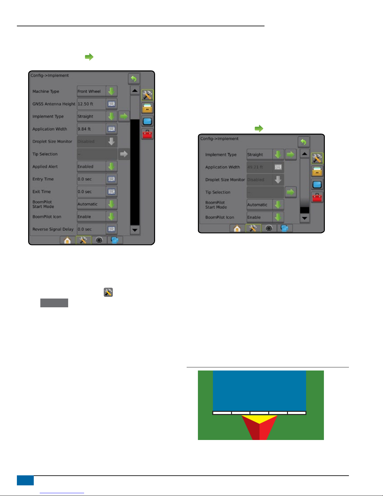
1. Press CONFIGURATION side tab .
2. Press Implement .
3. Select from:
►Machine Type [when available]– used to select the type of
machine that most closely represents your machine
►GNSS Antenna Height [when available]– used to measure the
height of the antenna from the ground
►Implement Type – used to select the layout of the sections for
the applied product location (see Implement Type section for
additional details)
►Working/ Application Width – used to enter the total width of the
implement. Range is 3.28 to 246.06 feet / 1.0 to 75.0 meters.
►Droplet Size Monitor [when available] – used to enable droplet
size monitoring for up to ve preselected sprayer tips
►Tip Selection [when available] – used to select the type of
sprayer tip (series and capacity) for determining droplet size
information
►Applied Alert – used to establish an alert to signal when exiting
or entering an applied area
►BoomPilot Start Mode – used to establish whether BoomPilot will
be controlled by speed or by the BoomPilot icon
4www.teejet.com
Aeros 9040 Field Computer
►BoomPilot Icon – used to activate the guidance screen icon for
manually controlling on-screen application painting
4. Press NEXT PAGE arrow to set up specic implement options.
See the Implement chapter for details.
Section(s) with ISOBUS Sprayer/Spreader Setup
Some Implement options are completed on the ISOBUS ECU. When
these options are also available in the Implement Setup section, they
will be grayed out or unavailable.
1. Press CONFIGURATION side tab .
2. Press Implement .
3. Select from:
►Machine Type [when available] – used to select the type of
machine that most closely represents your machine
►GNSS Antenna Height [when available] – used to measure the
height of the antenna from the ground
►Implement Type – used to select the layout of the sections for
the applied product location
►Application Width [Straight Implement Type completed on
ISOBUS ECU] – used to display the total width of the implement
as entered on the ISOBUS sprayer
►Working Width [Spreader Implement Type completed on the
ISOBUS ECU] – used to display the total width of the implement
as entered on the ISOBUS spreader
►Droplet Size Monitor [available only with Pressure Sensor
Interface Kit] – used to enable droplet size monitoring for up to
ve sprayer tips
►Tip Selection [Straight Implement Type completed on the
ISOBUS ECU] – used to display the type of sprayer tip as
entered on the ISOBUS sprayer
►Applied Alert – [only available without a switchbox] used to
establish an alert to signal when exiting or entering an applied
area
►BoomPilot Start Mode – used to control BoomPilot automatically
by speed, or manually by BoomPilot icon
►BoomPilot Icon – used to activate icon for manually controlling
BoomPilot
4. Press NEXT PAGE arrow to set up specic implement options.
Additional Settings per Implement Type
Implement Type selects the type of application pattern that most closely
represents your system.
● In Straight Mode – the boom sections have no length and are on
a line a xed distance from the antenna
● In Spreader Mode – a virtual line is created in line with the delivery
disks from which the application section or sections can vary in
length and can be at different distances from the line (availability
depends on the specic equipment in the system)
● In Staggered Mode – a virtual line is created in line with
Section 1 from which the application section or sections have no
length and can be at different distances from the line (availability
depends on the specic equipment in the system)
Figure 1: Implement Type – Straight
54321

5
98-01504-ENUS R2
Aeros 9040 Field Computer
Figure 2: Implement Type – Spreader
5
6
7
43
2
1
Figure 3: Implement Type – Staggered
5
432
1
Section Numbers
Sections are numbered from left to right while facing in the machine’s
forward direction.
Straight
The boom sections have no length and are on a line a xed distance
from the antenna.
1. Select Straight implement type on Implement screen.
2. Press Implement Type NEXT PAGE arrow .
3. Select from:
►Connection Point In-line Offset Direction [ISOBUS only] –
establishes if reference point is located in front of (forward)
or behind (backward) the GNSS antenna while facing in the
machine’s forward direction
►Connection Point In-line Offset Distance [ISOBUS only]–
measured in parallel to the centerline of the machine, denes the
in-line distance from the GNSS antenna to reference point
►Connection Point Lateral Offset Direction [ISOBUS
only]– denes the lateral direction, either left or right, from the
centerline of the machine to the center of reference point
while facing in the machine’s forward direction
►Connection Point Lateral Offset Distance [ISOBUS only]–
denes the lateral distance from the centerline of the machine to
the center of reference point
►Implement In-line Offset Direction – displays if the implement
is located in front of (forward) or behind (backward) the GNSS
antenna while facing in the machine’s forward direction
►Implement In-line Offset Distance – measured in parallel to
the centerline of the machine, displays the in-line distance from
the GNSS antenna to the implement
►Implement Lateral Offset Direction – displays the lateral
direction, either left or right, from the centerline of the machine
to the center of the implement while facing in the machine’s
forward direction
►Implement Lateral Offset Distance – displays the lateral
distance from the centerline of the machine to the center of the
implement
►Overlap – used to dene the amount of overlap allowed when
using automatic boom section control
►Delay On Time – used to set the time when the section will
switch on when entering an area that has not been applied
NOTE: If the application turns on too soon when entering an
unapplied area, decrease the Delay On Time. If the application
turns on too late, increase the Delay On Time.
►Delay Off Time – used to set the time when the section will
switch off when entering an area that has been applied
NOTE: If the application turns off too soon when entering an
unapplied area, decrease the Delay Off Time. If the application
turns off too late, increase the Delay Off Time.
*Available with SmartCable, Section Driver Module (SDM) or Switch
Function Module (SFM) or ISOBUS)

6www.teejet.com
Aeros 9040 Field Computer
Figure 4: Implement Offset Directions and Distances
Figure 5: Connection Point Offset Directions and Distances
– Center of the GNSS antenna
– Reference point
– Implement In-line Offset Direction/Distance
– Implement Lateral Offset Direction/Distance
– Connection Point In-line Offset Direction/Distance
– Connection Point Lateral Offset Direction/Distance
Spreader – TeeJet
A virtual line is created in line with the delivery disks from which the
application section or sections can vary in length and can be at different
distances from the line (availability depends on the specic equipment
in the system).
1. Select Spreader implement type on Implement screen.
2. Press Implement Type NEXT PAGE arrow .
3. Select from:
►Setup type – used to select TeeJet spreader type
►Antenna to Disks In-line Offset Distance – measured in
parallel to the centerline of the machine, denes the in-line
distance from the GNSS antenna to the disks, or dispersal
mechanism
►Implement Lateral Offset Direction – denes the lateral
direction, either left or right, from the centerline of the machine
to the center of the implement while facing in the machine’s
forward direction
►Implement Lateral Offset Distance – denes the lateral
distance from the centerline of the machine to the center of the
implement
►Overlap – used to dene the amount of overlap allowed when
using automatic boom section control
►Delay On Time – used to set the time when the section will
switch on when entering an area that has not been applied
NOTE: If the application turns on too soon when entering an
unapplied area, decrease the Delay On Time. If the application
turns on too late, increase the Delay On Time.
►Delay Off Time – used to set the time when the section will
switch off when entering an area that has been applied
NOTE: If the application turns off too soon when entering an
unapplied area, decrease the Delay Off Time. If the application
turns off too late, increase the Delay Off Time.
►Spread Offset Distance – used to set the distance between
the disks or dispersal mechanism and where product initially hits
the ground on Section 1.
►Section Offsets – used to set the offset distance from
section 1 (the Spread offset line) to the leading edge of each
section. Section 1 is always 0. All other sections can be different
distances.
►Section Lengths – used to set the length of application in
each section. Each section can be a different length.
NOTE: Sections are numbered from left to right while facing in
the machine’s forward direction.
*Available with SmartCable, Section Driver Module (SDM), or Switch
Function Module (SFM) or ISOBUS)

7
98-01504-ENUS R2
Aeros 9040 Field Computer
Figure 6: Distances and Length Figure 7: Lateral Offset Direction and Distance
– Center of the GNSS antenna
– Antenna to Disks In-line Offset Distance
– Implement Lateral Offset Direction/Distance
– Spread offset distance
– Section offsets
– Section lengths
Lateral Implement Offset Distance Adjustment
Lateral implement offset distance is used to enter the distance from
the center line of the machine to the center of the implement. When
on-screen mapping shows no overlap or gap, yet eld application
produces an overlap or gap consistently to only one side in the direction
of travel, an adjustment to the lateral implement offset distance should
be calculated and made to the implement offset distance value.
If using a self-propelled sprayer or spreader, use the GNSS Offset
Adjustment Calculation to calculate the implement offset distance
adjustment.
If using a pull behind or trailed implement, use the Implement Offset
Adjustment Calculation to calculate the implement offset distance
adjustment.
NOTE: While using assisted/auto steering, if on-screen mapping
shows overlaps and gaps, adjustments may need to be made
to the assisted/auto steering settings.
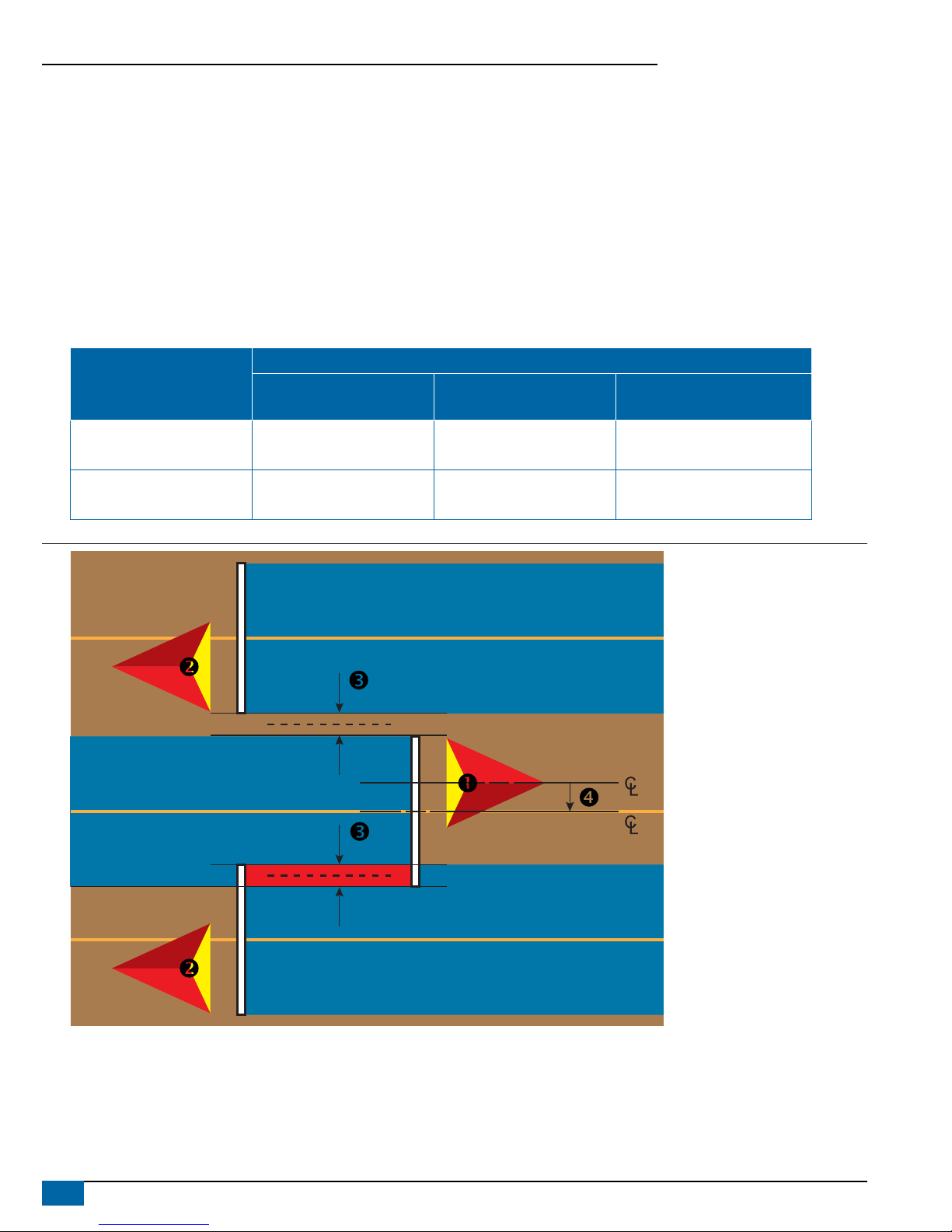
GNSS Offset Adjustment Calculation
To calculate a GNSS offset adjustment using the same guideline:
1. Create a straight AB line.
2. With assisted/auto steering engaged, drive pass at least 30
meters, and place ags at the draw bar or next to the machine.
3. Turn around and engage assisted/auto steering on pass on
the same AB guideline. Place ags at the draw bar or next to the
machine, or stop while on the AB guideline next to the ags you
placed on pass .
4. Measure the difference between the ags of pass and pass .
5. Divide the measured distance in half. This difference will be the
offset adjustment.
6. Increase or decrease the offset distance as needed dependent
on where the eld application overlap occurs and the current
implement offset direction setting.
Field Application Overlap
Current Offset Settings
Offset Direction = Left Offset Direction = Right
Offset Direction = Right
Offset Distance = 0 ft/m
To the right of pass Increase distance offset value Decrease distance offset value Increase distance offset value
To the left of pass Decrease distance offset value Increase distance offset value Change to implement offset direction to
left and increase distance offset value
Figure 8: GNSS Offset Distance
8www.teejet.com
Aeros 9040 Field Computer
Lateral Implement Offset Adjustment
To calculate an implement offset adjustment using adjacent guidelines:
1. Create a straight AB line.
2. With assisted/auto steering engaged, drive pass as if you were operating the implement, and place ags at the outside edges of the
implement.
3. Turn around and engage assisted/auto steering on pass on the adjacent AB guideline. Place additional ags at the outside edges of the
implement or stop while on the AB guideline next to the ags you placed on pass .
4. Measure the difference between the ags of pass and pass .
5. Divide the measured distance in half. This difference will be the offset adjustment.
6. Increase or decrease the offset distance as needed dependent on where the eld application overlap occurs and the current implement
offset direction setting.
Field Application
Current Offset Settings
Offset Direction = Left Offset Direction = Right
Offset Direction = Right
Offset Distance = 0 m
Overlap on the right of pass or
Gap on the left of pass Increase distance offset value Decrease distance offset value Increase distance offset value
Overlap on the left of pass or
Gap on the right of pass Decrease distance offset value Increase distance offset value Change to implement offset direction to
left and increase distance offset value
Figure 9: Lateral Implement Offset Distance and Direction

9
98-01504-ENUS R2
Aeros 9040 Field Computer
4) Set Up the Mapping Location
Mapping location establishes the location from which boundary and
polygon mapping will take place.
1. Press CONFIGURATION side tab .
2. Press Mapping and Guidance .
3. Select from:
►Mapping Location – establishes the layout of the location from
which the boundary or polygon will be mapped.
● Default Location – While creating an exterior boundary or
polygon, the line will be to the exterior of the outermost active
section. While creating an interior boundary, the line will be
to the interior of the innermost active section. If no sections
are active, the boundary will be marked to the end of the
outermost section.
● User Entry – in-line and lateral offset from the GNSS antenna
directions and distances can be specied by the user. Up
to ve (5) user entries can be created. See “User Entered
Mapping Location” for details.
►Guidance Width – used to set the distance between guidelines
►Guidance Sensitivity – sets the distance around the guideline that
is perceived as zero error.
4. Select user entry location from the Mapping Locations drop-down
options.
5. Press MAPPING LOCATION NEXT PAGE arrow to set up the
selected specic mapping location options.
6. Select:
►Location Name – used to enter the name of the mapping location
for the current user entry selected
►Mapping Location In-line Offset Direction – used to select
whether the mapping location is located in front of or behind the
GNSS antenna as the vehicle moves in a forward direction
►Mapping Location In-line Offset Distance – used to dene the in-
line distance from the GNSS antenna to the mapping location
►Mapping Location Lateral Offset Direction – used to select
the lateral direction from the centerline of the machine to the
mapping location while facing in the machine’s forward direction
►Mapping Location Lateral Offset Distance – used to dene
the lateral distance from the centerline of the machine to the
mapping location
7. Press RETURN arrow to return to the Mapping and Guidance
screen or CONFIGURATION side tab to return to the main
Conguration screen.
Figure 10: User Entered Mapping Location
Default Location
User Entry 1
User Entry 2
User Entry 3
User Entry 4
User Entry 5

10 www.teejet.com
Aeros 9040 Field Computer
#4 START NEW JOB OR CONTINUE JOB
Once the power up sequence has completed, the Home screen will appear with the option to start a new job or continue an existing job. The
console must have GNSS before starting or continuing a job. Setup for the specic machine and its components must be
completed before starting a job. Once a job is active, some setup options can no longer be changed. To change between simple and
advanced mode, go to Data-> Options-> Job Mode in the System Setup.
Simple Mode
In simple mode, only one job will be available at a time.
New Job
1. On the Home screen , press New Job .
Continue Job
1. On the Home screen , press Continue .
If the current job is in a UTM zone other than the current or adjacent
UTM zone Continue will be disabled.
Close Job
1. On the Home screen , press Close Job .
To create a report of the job when closing a job, Insert a USB drive into
the USB port of the console before pressing “Close Job”.
Advanced Mode
In advanced mode, more than one job will be available at any time.
Client information, farm information, eld information, and prescription
maps can only be inputted using Fieldware Link. A job name can only
be edited using Fieldware Link.
A user can duplicate jobs for reuse of guidelines, boundaries, applied
data, prescription map and/or polygons using Fieldware Link or
Data -> Job Data -> Manage in the console.
New Job
1. On the Home screen , press New Job .
2. Press:
►Yes – to automatically generate a name
►No – to enter a name using the on screen keyboard
Client, farm, and eld information are inputted using Fieldware Link.
Start Job
The Aeros 9040 is programmed with a eld nder tool to assist the user
in nding the job closest to the vehicle’s location. With GNSS acquired,
the job pick list will be updated every ten seconds. During this update,
the list of jobs is sorted by distance and the closest two jobs are
displayed on the top of the list. The remaining jobs are listed beneath
these.
1. On the Home screen , press DOWN arrow to access the list
of jobs saved in the console.
2. Select the job name to be started/continued.
3. Press Start Job .
Close Job
1. On the Home screen , press Close Job .
To create a report of the job when closing a job, Insert a USB drive into
the USB port of the console before pressing Close Job .

11
98-01504-ENUS R2
Aeros 9040 Field Computer
#5 SET UP GUIDANCE
1) Choose a Guidance Mode
Three guidance screens assist in keeping you informed.
VehicleView guidance creates a
computer-generated image of the vehicle
position displayed in the application area.
FieldView guidance creates a computer-
generated image of vehicle position and
application area from an aerial perspective.
RealView guidance allows live video
input to be displayed instead of a computer-
generated image.
6.1
mph
7.62
ac 0.0
55
(psi)
6.1
mph
7.62
ac Mark A 6.1
mph
7.62
ac 0.0
To choose a guidance mode:
2. Press NAVIGATION AND GUIDANCE OPTIONS tab to display
navigation options.
3. Press GUIDANCE MODE icon .
4. Select from:
►No Guidance
►Straight AB Guidance
►Curved AB Guidance
►Circle Pivot Guidance
►Last Pass Guidance*
►NextRow Guidance*
►Adaptive Curve Guidance
*Guidance options may not be available depending on assisted/
automatic steering system installed.
Figure 11: Choose a Guidance Mode
0.0
mph
0.00
ac Mark A
0.0
mph
0.00
ac Mark A

12 www.teejet.com
Aeros 9040 Field Computer
2) Establish an AB guideline
1. Drive to the desired location of Point A .
2. Press NAVIGATION AND GUIDANCE OPTIONS tab to display
navigation options.
3. Press MARK A icon .
4. Drive to the desired location of Point B .
5. Press MARK B icon to establish the AB line.
6. “Would you like to name this guideline?”
Press:
►Yes – to enter a name and save the guideline in the console
►No – to automatically generate a name and save the guideline in
the console
The console will begin providing navigation information.
NOTE: The MARK B Icon is not available for selection (grayed out)
until the minimum distance is travelled (9.84 feet / 3.0 meters in
Straight or Curved guidance, 164.04 feet / 50.0 meters in Circle
Pivot guidance).
NOTE: It is not necessary to drive the entire circumference of the
center pivot in order to initiate Circle Pivot Guidance.
Use CANCEL MARK icon to cancel the Mark A command and
revert to the previous guideline (when established).
Figure 12: Mark A Point
1:12 pm
7.2
mph
Mark A
Figure 13: Mark B Point
1:14 pm
7.2
mph
Mark B
3) Create an Application Boundary
Available on any guidance screen, the Boundaries and polygons tab
displays exterior boundary, interior boundary and polygon options.
Application boundaries establish the work areas where product is or is
not applied while using ASC or BoomPilot.
• Exterior Boundary – establishes a work area where
application will be applied while using ASC or BoomPilot.
• Interior Boundary – establishes a work area where application
will NOT be applied while using ASC or BoomPilot.
Boundaries can be established in all guidance modes. Up to 100 total
exterior boundary and/or interior boundaries can be stored within a
single job. Application is not required to map a boundary.
Using Data -> Job Data -> Manage or with Fieldware Link, a user can
duplicate and edit jobs for reuse of boundaries for different applications
over the same eld.
Application is not required to map a boundary or polygon.
If mapping a boundary or polygon with one or more sections folded
in and turned off, it is necessary to maintain this section conguration
for the duration of the boundary or polygon pass. Any changes made
to the number of sections turned on, and therefore the width of the
machine after the boundary or polygon mapping process has started,
will result in the application mapping the boundary or polygon at the
outer edge of all the programmed sections – not necessarily those
turned on at any given time during the boundary or polygon pass.
When mapping a boundary or polygon with some sections turned off,
it is necessary to turn BoomPilot to Manual mode and turn ON the
master and section switches for all sections that will be used during
the boundary or polygon pass. Once the boundary or polygon pass
is complete the sections switches can be turned OFF, master switch
remains ON, BoomPilot can be returned to Automatic mode and
automatic section control can then be used.
NOTE: If a boundary is mapped with some sections folded
as described above, it may be necessary to use the
A+ NUDGE icon on the guideline over to the correct
position for subsequent passes in the field.
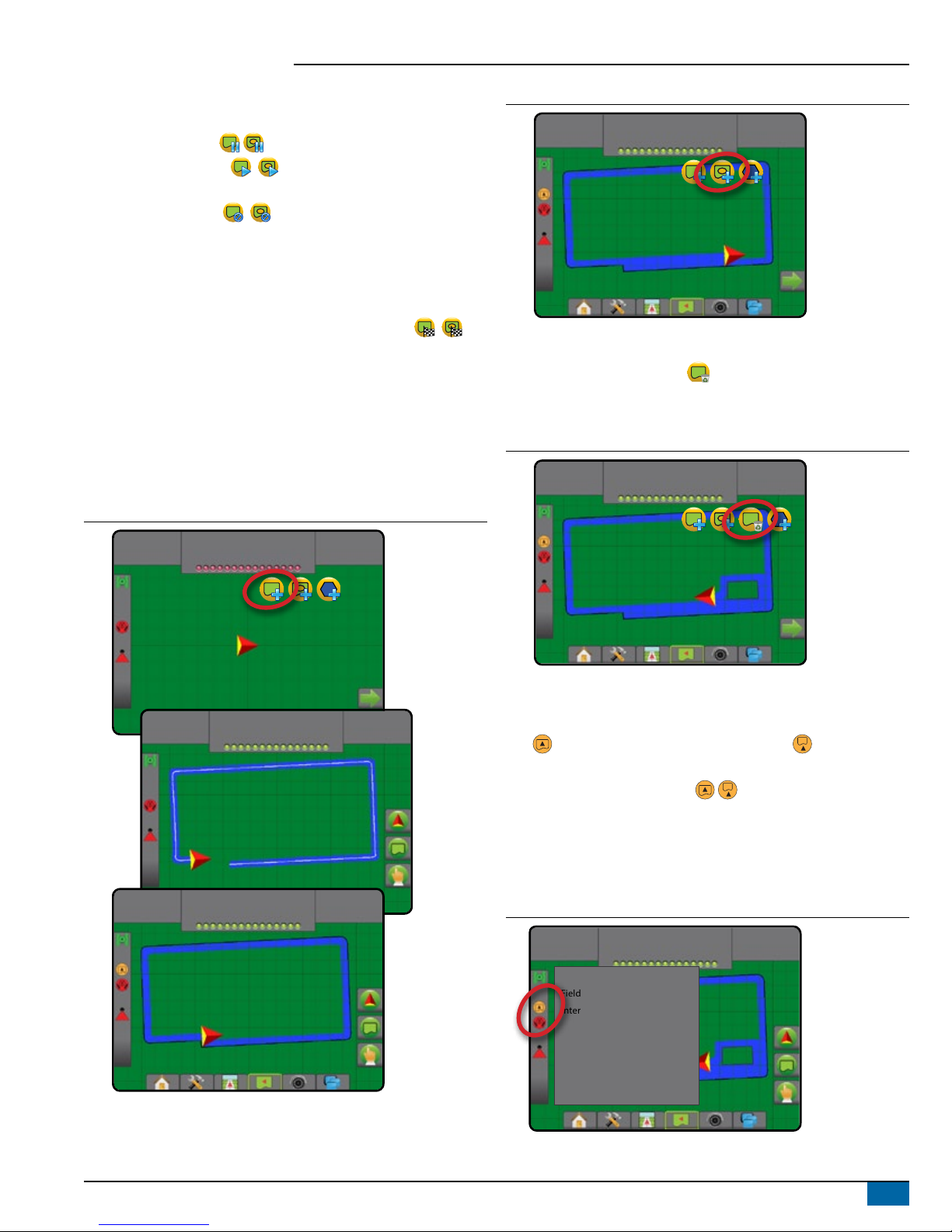
Establishing an Exterior or Interior Boundary
To establish an exterior or interior boundary:
1. Drive to a desired location at the perimeter of the application
area and orientate the vehicle in association to the established
mapping location.
2. Press BOUNDARY AND POLYGON OPTIONS tab to display
boundary and polygon options.
3. Press MARK BOUNDARY icon .
4. Verify that the Mapping location is correct.
◄If the Mapping location is not correct, press Cancel then go to
Configuration-> Mapping and guidance-> Mapping location.
13
98-01504-ENUS R2
Aeros 9040 Field Computer
5. Travel the perimeter of the application area.
While traveling, use as needed:
►Pause Boundary – pauses the mark boundary process.
►Resume Boundary – resumes the mark boundary
process.
►Cancel Boundary – cancels mark boundary process.
6. Finish the boundary:
►Automatic close – travel to within one swath width of the starting
point. The boundary will close automatically (the white guideline
will turn black).
►Manual close – press the FINISH BOUNDARY icon
to close the boundary with a straight line between the current
location and the starting point.
NOTE: If the minimum distance is not travelled (five times the
swath width), an error message will pop-up.
7. Press:
►Save – to save the boundary
►Delete – to delete the boundary
Figure 14: Exterior Boundary
0.00
ac
0.0
mph
2.32
ac
7.2
mph
3.68
ac
7.2
mph
Figure 15: Add Interior Boundary
4.55
ac
7.2
mph
Delete Last Marked Boundary
Use DELETE BOUNDARY icon to delete the last marked boundary
(interior or exterior) from the current job. Press again to remove
additional boundaries in order from last to rst created.
Figure 16: Delete Last Marked Boundary
7.03
ac
7.2
mph
Boundary on Status Bar
In reference to your current location, the IN EXTERIOR BOUNDARY
icon or OUT OF EXTERIOR BOUNDARY icon
is displayed on the Status Bar once a boundary is established.
1. Press BOUNDED AREA icon .
◄Working Area – total are of all exterior boundaries
◄Field Area – total area of all exterior boundries minus the area of
all interior boundaries
◄Internal Area – total area of all interior boundaries
Figure 17: Boundary on Status Bar
7.03
ac
7.2
mph
Working area: 61.22 ac
Field area: 64.45 ac
Internal area: 3.23 ac

14 www.teejet.com
Aeros 9040 Field Computer
ADD RATE CONTROL
NOTE: TeeJet Dual Control Module (DCM) is no longer supported and
will not be referenced in this manual.
ISOBUS universal terminal (UT) gives access to an ISOBUS electronic
control unit (ECU) options and operation. This provides crop sprayer or
spreader control when integrated into the implement of either capability.
NOTE: For detailed setup instructions, refer to the specific ISOBUS
user manual for the connected ECU.
1. Press UNIVERSAL TERMINAL bottom tab .
20.00
gal/ac
66.00
ac
Mark A
Soft Keys Area
Active ISOBUS ECUs Available on System
Activity Window
Ready for Operation
Upon starting up the system, an ISOBUS product may take a few
minutes to load all required information or object pools.
Before starting a job, check to be sure the ISOBUS ECU is ready.
• Home Screen is available
• Tack Control (TC) is active – Active Trip Count Number should
show “TC”
20.00
gal/ac
66.00
ac
Mark A
Guidance Screen Options
When a ISOBUS Electronic Control Unit (ECU) sprayer or spreader
control is integrated into the implement, rate control options and
mapping options are available on the Vehicle View and Field View
guidance screens.
Application Control Options Tab
Current Pressure
Mapping Options Tab
10.0
mph
55
(psi)
27.00
ac Mark A
Guidance Bar
Current Pressure
Displays the current pressure to the tip.
Guidance Bar
In addition to the standard Guidance bar options, the following
selectable information will become available with an ISOBUS ECU:
►Actual Application Rate – displays the current application rate
►Target Application Rate – displays the target application rate
►Volume/Product Applied – displays the volume or weight of
product applied
►Tank/Bin Amount Remaining – displays the volume or weight of
product remaining in the tank/bin
10.0
mph
55
(psi)
27.00
ac Mark A
System Pressure
Actual
Application Rate
Droplet Size
Target
Application Rate
Volume/Product
Applied
Tank/Bin Amount
Remaining

15
98-01504-ENUS R2
Aeros 9040 Field Computer
Mapping
GNSS-based product application mapping is available in Vehicle
View or Field View. Mapping can record areas covered by the
implement (Coverage) or how much product has been applied and
where (Application) and can direct single- and variable-rate product
application (Preset Target Rate and Prescription, respectively).
NOTE: For more information, see “Application Mapping”.
1. Press VEHICLE VIEW GUIDANCE bottom tab . or FIELD
VIEW GUIDANCE bottom tab .
2. Press MAPPING OPTIONS tab to display mapping options.
3. Select one or more:
►Coverage Map
►Polygons
►Prescription Map
►Application Map
►Target Rate Map
NOTE: Application Map and Target Rate Map cannot be selected
simultaneously.
10.0
mph
27.00
ac Mark A
27.00
ac
10.0
mph
Mark A
Application Control
Target Rate Percentage Increase/Decrease icons increase/decrease
the application target rate per the established percentage set in
the Machine Operation setup screen under Application Rate Step.
Automatic regulation mode will automatically adjust the application rate
based on the current speed in reference to the target rate.
NOTE: The Target Rate Percentage Increase/Decrease icons do the
same adjustment as the Boost/Step Percentage Increase/
Decrease Keys from the ISOBUS UT.
1. Press VEHICLE VIEW GUIDANCE bottom tab .
2. Press APPLICATION OPTIONS tab .
3. Select from:
►Target Rate Percentage Increase – establishes the required
boost percentage step increase
►Target Rate Percentage Decrease – establishes the required
boost percentage step decrease
►Percentage Boost and Reset – shows current boost
percentage step and when pressed, zeros the boost percentage
step
10.0
mph
55
(psi)
27.00
ac Mark A
MAPPING OPTIONS
On vehicle view or eld view guidance screens, in any guidance mode,
the mapping options tab displays options to display polygon maps,
coverage maps and application maps.
Polygon and coverage mapping are available when a polygon has
been established.
GNSS-based product application mapping is available when a rate
controller is on the system. Rate control mapping can record areas
covered by the implement (Coverage) or how much product has
been applied and where (Application), and can direct single- and
variable-rate product application (Preset Target rate and Prescription,
respectively).
NOTE: Before using mapping, set or verify product mapping options
under Configuration->Product.
Duplicating and Transferring Maps
Maps are stored in the job data. Using Data->Job Data, job data
containing maps can be duplicated or transferred to Fieldware Link so
the maps can be opened, viewed, edited, and printed, and transferred
back to the console. See “Data management->Job data->
Transfer” and “Data Management-> Job Data-> Manage” in the System
Setup chapter for details.
Using Data->Reports, reports in multiple formats can be generated
that contain data and any maps from the job.

16 www.teejet.com
Aeros 9040 Field Computer
To access application mapping:
1. Press VEHICLE VIEW GUIDANCE bottom tab or
FIELD VIEW GUIDANCE bottom tab .
2. Press MAPPING OPTIONS tab to display mapping options.
3. Select one or more:
►Coverage map – shows areas covered by the implement,
regardless of whether product was applied
►Polygons – shows all mapped polygons
►Prescription map – pre-loaded map that provides information
to the rate controller for use in applying product
►Application map – shows how much product has been
applied and where, using color to indicate level in proportion to
preset or automatically set maximum and minimum levels
►Target Rate map – shows the application rate that the rate
controller attempted to achieve at each location
NOTE: Application Map and Target Rate map cannot be selected
simultaneously.
Figure 18: Coverage, Polygon and Target Rate Maps
10.0
mph
27.00
ac Mark A
27.00
ac
10.0
mph
Mark A
Coverage Map
Coverage map showing areas covered by the implement.
ISOBUS requires product to be applied.
• Coverage area – illustrates applied area and overlap:
◄Blue – one application
◄Red – two or more applications
27.00
ac
10.0
mph
Mark A
Polygons Map
Polygon map shows all mapped polygons.
• Guidelines
◄Blue – polygon boundary line
27.00
ac
10.0
mph
Mark A
Prescription Map
Prescription map is a pre-loaded map that provides information to
the rate controller for use in applying product. Prescription maps
contain geo-referenced product rate information. The Aeros 9040 can
import job data containing Prescription maps for use with variable-rate
application (VRA) using compatible rate controllers.
• Zone Lines:
◄Black when approaching the application zone.
◄White when within the application zone.
◄ Other zones having the same rate will also be shown in white.
• Coverage Area – illustrates different prescription rate zones:
◄ User selected – zone colors are selected when establishing the
prescription map.
With Fieldware Link (v5.01 or later), users can import VRA jobs created
in Fieldware Link, as well as export job data from the console, edit the
included maps to create Target rate or Prescription maps, and transfer
back to the console for job use.
NOTE: Advanced Job Mode is required for variable rate applications.
See Options (Job mode) in the System Setup chapter.
27.00
ac
10.0
mph
Mark A
Table of contents


