Ocean Systems dTective User manual

1
Connecting Video and Audio to RackMount and Tower dTective
Systems Using Media Composer Adrenaline
Pages 2 - 7: Connecting S-Video Cables
Page 8: S-Video Wiring Diagram
Pages 9 - 13: Connecting Composite Cables
Page 14: Composite Wiring Diagram
Page 15 - 18: Connecting Audio Cables
©2005 Ocean Systems.
This document cannot be reproduced or transmitted by any means without the express written permission of
Ocean Systems.
You should have the following cables for video:
Three S-video Cables Four Composite Cables Five BNC to RCA converters
One Speaker Tap
You should have the following cables for audio:
Two XLR Female to
RCA Female Converters Two XLR Male to RCA
Female Converters Two separate pairs of RCA
Cables

2
Connecting Your Video Cables to the dTective System
Connecting an S-Video Deck to the dTective System
Not sure what type of connections to use? Take a look at the images below:
The image below shows a typical S-Video deck. If your deck has this style of connectors, you
need to follow the instructions for connecting S-VIDEO, as outlined starting on this page.
Use S-Video cables if your deck looks like the image above
The image below shows a typical consumer grade VCR with composite (RCA) style IN and
OUT connectors. If your deck has this style of connectors, you need to follow the instructions
for connecting Composite Cables, as outlined on page 9.
Use composite cables if your deck looks like the image above (see page 8)
What you will need:
Three S-video Cables
One Composite Cable

3
Step 1: Connecting S-Video Cable to S-Video OUT on rear of deck (VCR)
Take one of your three S-Video cables and connect it to the S-Video OUTPUT port on the rear
of your deck as shown below:
Step 2: Recognizing the TBC
The TBC is an external box designed to “lock down” poorly synced video. The image below
shows the external TBC.
External TBC

4
Step 3: Connecting S-Video cable to INPUT on TBC
Take the cable that you just connected to the rear of the deck and connect the other end of it to
the S-Video INPUT on the front of the TBC (out from deck to TBC input).
Step 4: Connecting S-Video cable to OUTPUT on TBC
Take a second S-Video cable and connect it to any of the four S-Video outputs on the rear of
the TBC
Connect S-Video to any of the four outputs

5
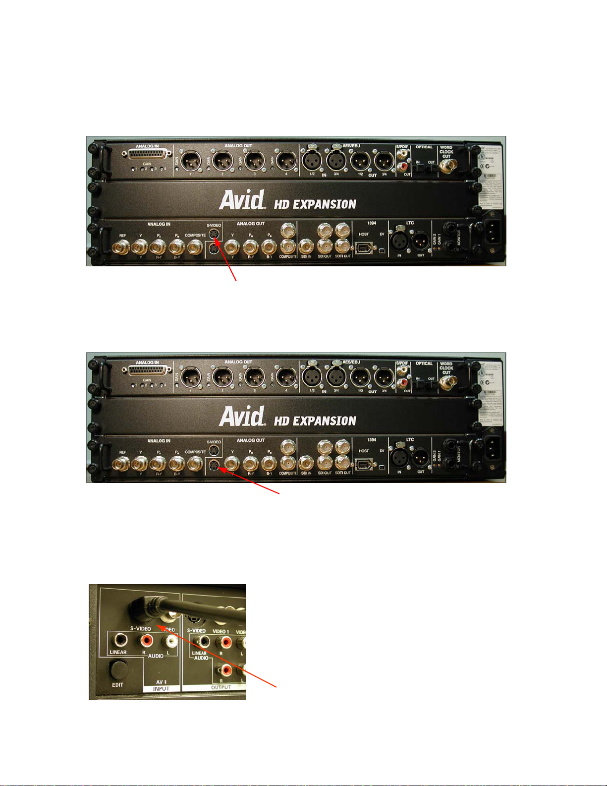
Step 5: Connecting S-Video cable to INPUT on the Break Out Box
Take the cable that you just connected from the output of the TBC and connect the other end
to the S-Video INPUT on the rear of the Avid Break Out Box.
Connect S-Video cable from TBC OUT to S-Video IN on BOB
Step 6: Connecting S-Video cable to INPUT on the deck
Take a third S-Video cable and connect it to the S-Video OUT on the rear of the Break Out Box
as shown below:
Connect S-Video cable to S-Video OUT on Break Out Box
Take the other end of the cable running from the S-Video out on the Break Out Box and con-
nect it to the S-Video INPUT on the deck.
Note: On Panasonic AG-1980 decks, it is recommended that you use the inputs on the front to eliminate any feedback
you may encounter when digitizing.
Connect S-Video cable from S-Video OUT on the BOB to S-Video IN on deck

6
Step 7: Connecting your NTSC Monitor (TV)
You need to determine if your television monitor uses a BNC connector or an RCA connector.
Take a look at the images below to determine what you have. You will use either of these type
of connectors, but not both.
BNC Input:
RCA Input:
After determining which type of connector you will be using, connect your composite BNC cable
to any one of the three Composite Outputs on the Break Out Box as shown below:
Connect a composite BNC cable to the composite OUT on the Break Out

7
Connect the other end of the cable from the composite out of the Break Out Box to the Video
IN on your NTSC monitor (TV) as shown below. The images below show connections for both
BNC and RCA. Remember, you will connect either of the two connector styles (BNC or RCA),
but not both.
BNC Input - connects directly to monitor:
RCA Input - requires provided adapter:
If you are using an RCA input, you will need to use the provided BNC to RCA adapter. The
images below show how the adapter attaches:
The adapter will twist and lock into place
Once the adapter has been properly fastened, connect the cable to the Video IN on your TV as
shown below:

8

9
Connecting a Composite VCR to the dTective System
What you will need:
Four Composite Cables
Five BNC to RCA converters
Step 1: Connecting Composite Cable to RCA OUT on rear of VCR
Take one of your four composite cables and connect it to the Video OUT port on the rear of
your VCR.
You will need to use the provided BNC to RCA adapter. The images below show how the
adapter connects:
The adapter will twist and lock into place
Connect the Composite cable (with converter) to Video Out on VCR

10
Step 2: Recognizing the TBC
The TBC is an external box designed to “lock down” poorly synced video. The image below
shows the external TBC.
External TBC
Step 3: Connecting Composite cable to INPUT on TBC
Take the cable that you just connected to the rear of the deck and connect the other end to the
RCA INPUT on the front of the TBC (out from deck to TBC input).
Connect Cable from OUTPUT of VCR to INPUT on TBC:

11
Step 4: Connecting Composite cable to OUTPUT on TBC
Take a second Composite cable (with converter) and connect it to any of the four RCA outputs
on the rear of the TBC
Connect Composite cable to any of the four outputs
Step 5: Connecting Composite cable to INPUT on the Break Out Box
Take the cable that you just connected from the output of the TBC and connect the other end
to the Composite INPUT on the rear of the Avid Break Out Box (connects directly with no
adapter).
Connect a Composite cable from TBC OUT to Composite IN on Break Out Box

12
Step 6: Connecting Composite cable to INPUT on the VCR
Take a third composite cable (with one converter) and connect it to the lower Composite OUT
on the rear of the Break Out Box as shown below (no converter needed to connect to Break
Out Box):
Connect a composite BNC cable to the composite OUT on the Break Out
Take the other end of the cable running from the composite out on the Break Out Box and con-
nect it to the Video INPUT on the deck.
Connect composite cable (with converter on this end) from the composite OUTPUT
on the Avid BOB to Video IN on the VCR

13
Step 7: Connecting your NTSC Monitor (TV)
Connect a fourth composite cable (with one converter) to upper Composite Output on the
Break Out Box as shown below:
Connect the other end of the cable from the composite out of the Break Out Box to the Video IN
on your TV as shown below (use converter on this end).

14

15
Connecting Your Audio Cables to the dTective System
Connecting Audio to the dTective System
What you will need:
“Speaker Tap”
Two separate pairs of RCA Cables
Female XLR to Female RCA Converters
Step 1: Connecting the Speaker Tap to the Break Out Box
Take the female end of the Speaker Tap and connect it to the Analog Out ports on the Break
Out Box as shown below.
Male XLR to Female RCA Converters
Connect Speaker Tap here:

16
Step 2: Connect the XLR to RCA Converters to the Speaker Tap
Connect the XLR to RCA Converters to the Male XLR connections on the Speaker Tap as
shown below.
Step 3: Connect the RCA Cable to Converters
Connect the RCA cable to the XLR converters on the Speaker Tap as shown below.
Step 4: Connect the RCA Cables to Audio IN on the VCR
Connect the RCA cables from the Speaker Tap to the port labeled Audio IN on your VCR as
shown below.

17
Step 5: Connect the Mini Cable from the Speaker Tap to the Speakers
The Speaker Tap allows you to connect to your VCR as well as your speakers. Using the
smaller “mini” cable, connect to the IN on your speakers.
Connect to speakers using this cable
Standard Speakers

18
Step 6: Connect the ADR “Medusa” cable to the Break Out Box
Use the provided “Medusa” cable and connect it to the Break Out Box using the port labeled
“Analog In”.
Step 7: Connect the RCA Cables from the Medusa cable to your VCR
The “Medusa” cable includes RCA connections. Connect one left channel and one right chan-
nel RCA cable to the “audio out” connection on your VCR, as shown below (image below is for
example only - actual VCR and RCA connectors may vary.)
Connect “Medusa” cable here:
Connects to “Analog In’ on Break Out Box
RCA connectors
Adrenaline “Medusa” Cable

19
Audio Cables Configured
The image below shows a typical Avid ADR audio configuration
Other manuals for dTective
1
This manual suits for next models
1
Other Ocean Systems Desktop manuals