© 2005 D545 - 06/05 2 of 40
Table of Contents
Table of Contents............................................................2
Display and DIP Switches ..............................................2
Dip Switches ...........................................................2
Access Levels .........................................................3
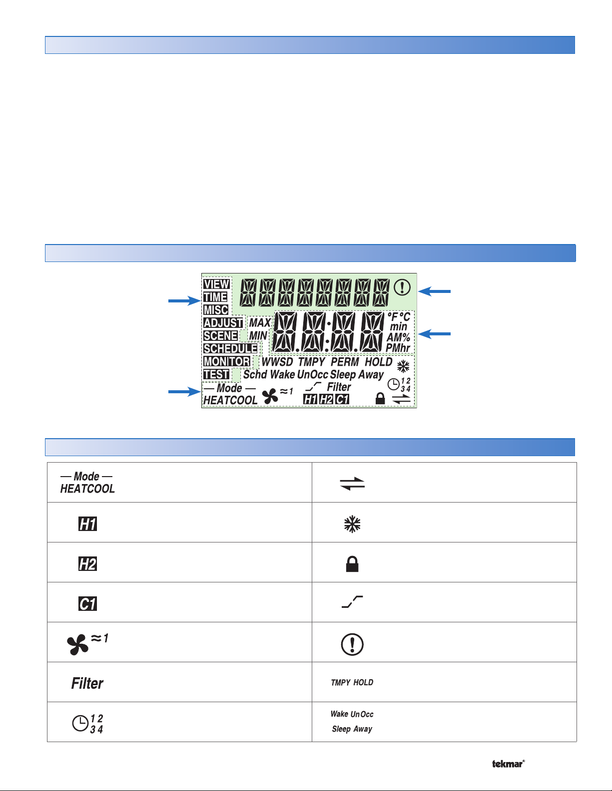
Display and Symbols Description ...........................3
User Interface .........................................................4
Setup ..............................................................................5
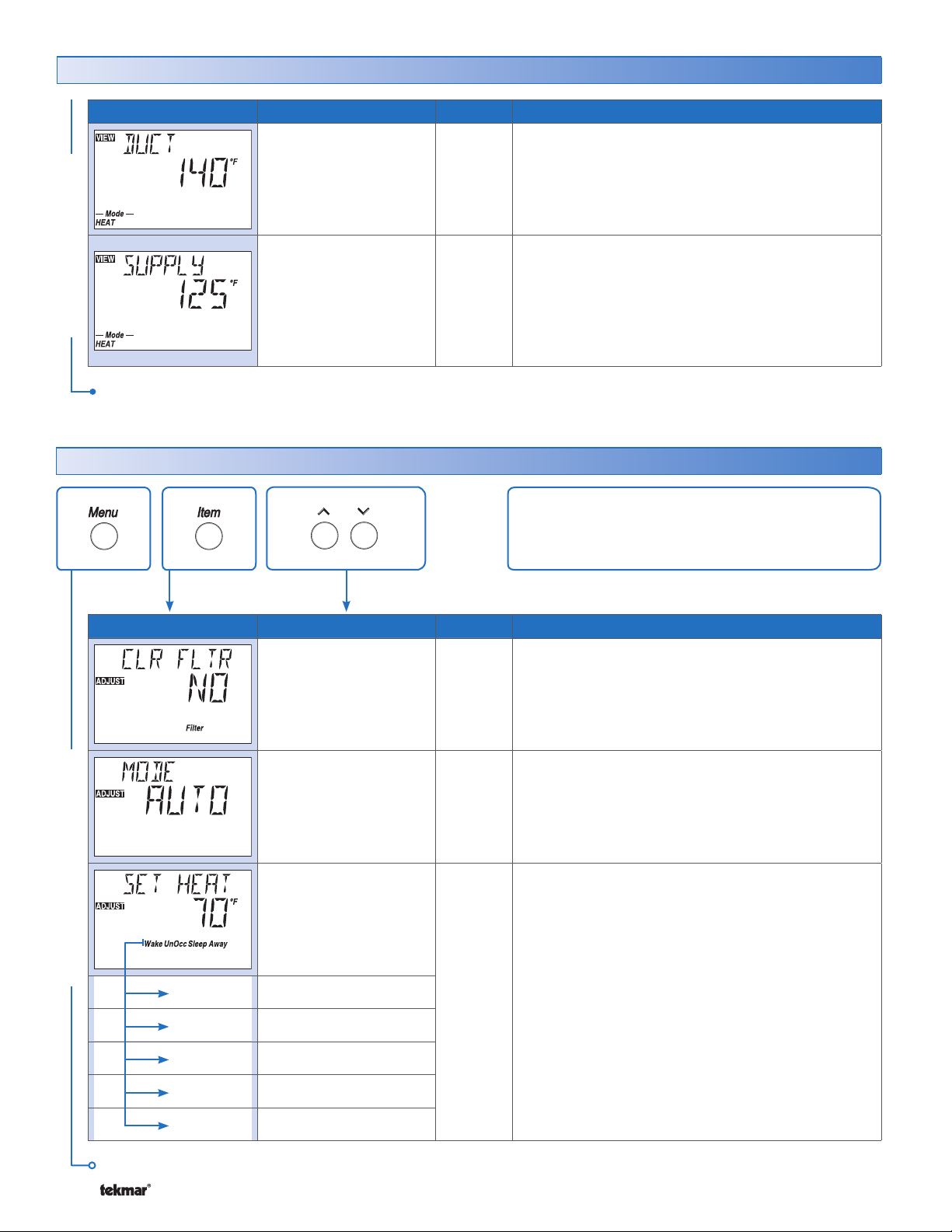
View Menu .............................................................5
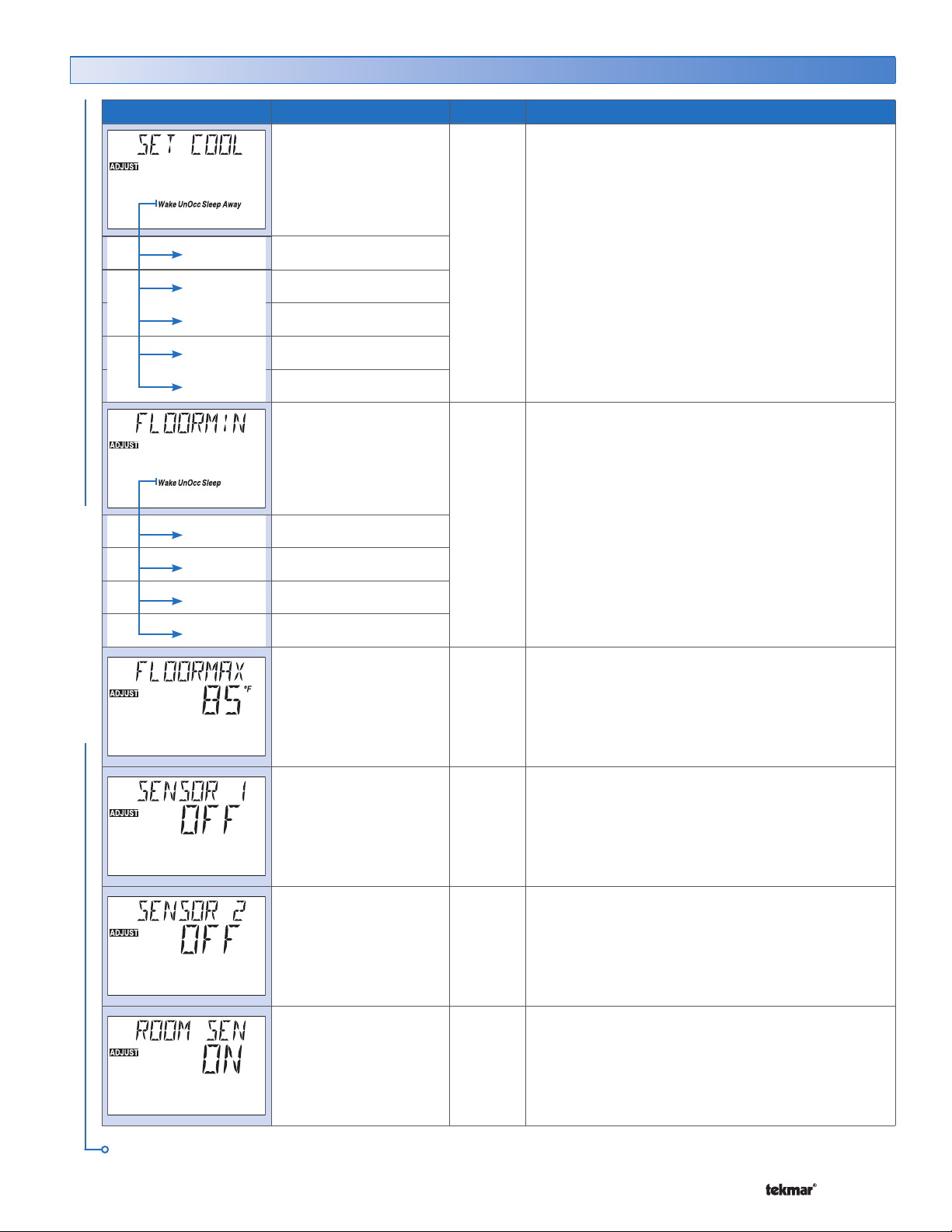
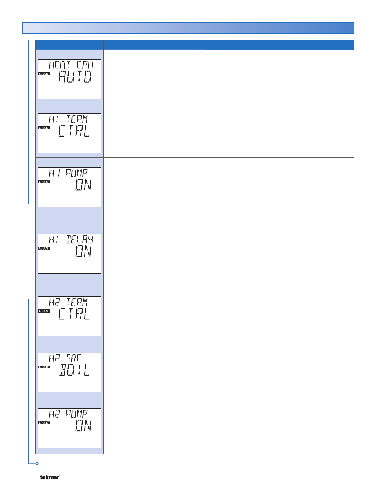
Adjust Menu............................................................6
Time Menu ............................................................ 13
Scene Menu.......................................................... 14
Schedule Menu.....................................................16
Monitor Menu........................................................19
Test Menu ............................................................21
Miscellaneous Menu ............................................22
Testing .........................................................................23
Thermostat Operation ..................................................24
Auxiliary Sensors .................................................24
Heat or Cool Mode of Operation ..........................25
Adjusting the Temperature ...................................25
Cycles Per Hour ...................................................26
Heating Terminal Units .........................................26
Heating Operation ................................................27
Cooling Operation ................................................29
Cool Groups .........................................................29
Fan Operation ......................................................30
Filter Change .......................................................31
Time Clock ........................................................... 31
Setting the Schedule.............................................32
Optimum Start / Stop ...........................................33
Scenes .................................................................33
Away Hold ............................................................34
Radiant Base Load ..............................................35
Offset ...................................................................35
Warm Weather Shutdown ....................................35
Cold Weather Shutdown ......................................35
Units of Temperature ............................................35
Backlight ..............................................................35
tN4 Address .........................................................36
Error Messages ............................................................36
Cleaning the Thermostat ......................................39
Warranty .......................................................................40
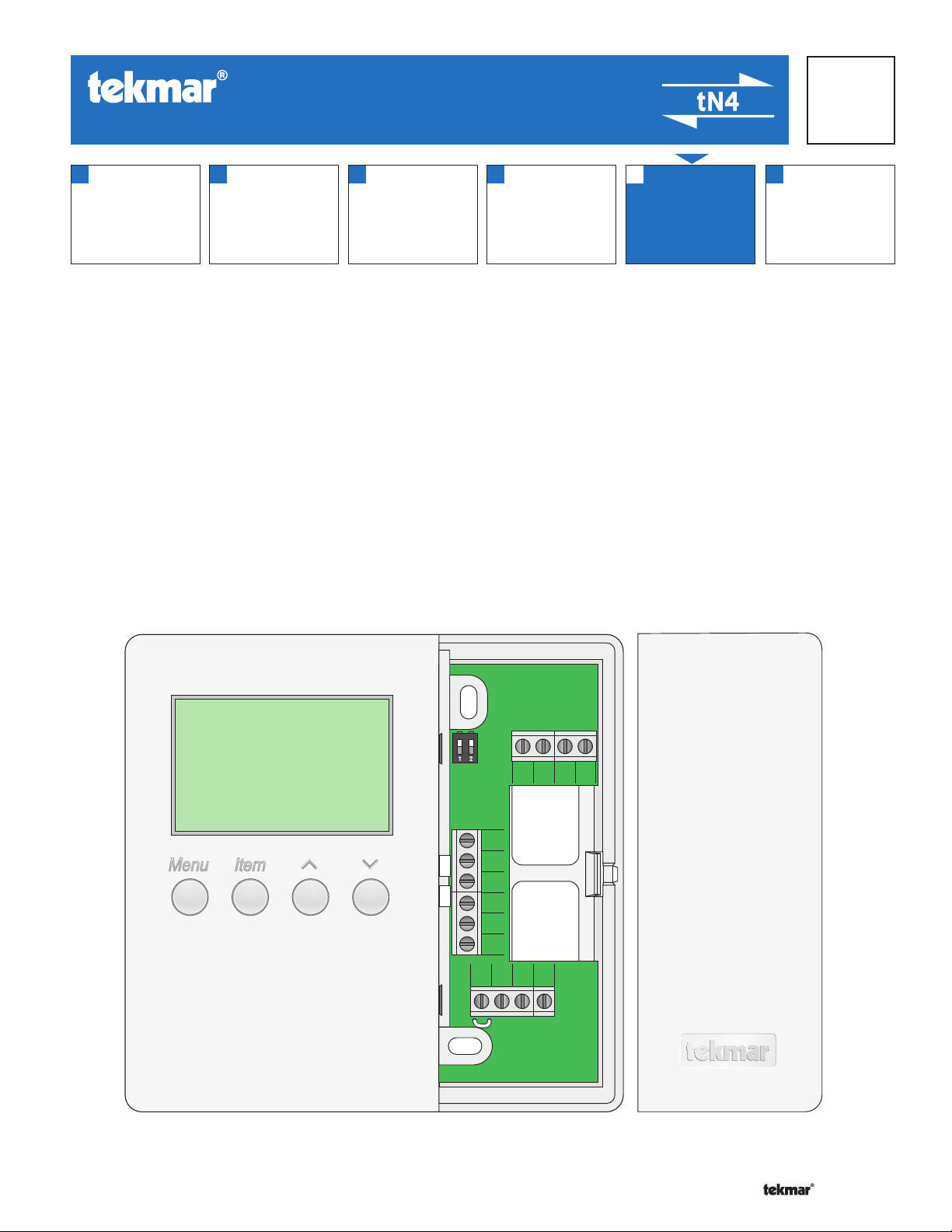
Display and DIP Switches
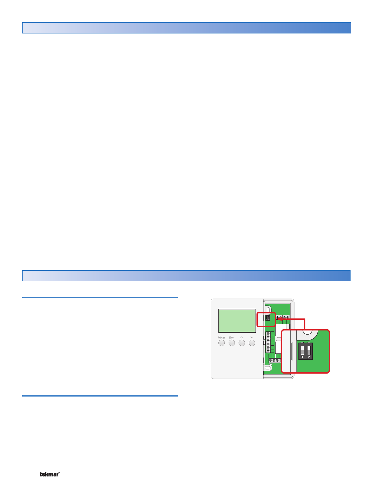
Dip Switches
Y1 Rc G1 G1
R
C
tN4
S1
S2
Com
W1
Rh1 Rh2
W2
tN4 System Control (DIP Switch #2)
A tN4 System Control is a control, not a thermostat, that
the 545 thermostat connects to through the tN4 bus. All
tN4 compatible Outdoor Reset Modules are tN4 System
Controls.
• If the thermostat is connected to a tN4 System Control,
set the tN4 System Control DIP switch to tN4 System
Control.
• If the thermostat is not connected to a tN4 System
Control, set the tN4 System Control DIP switch to
None.
Lock/Unlock (DIP Switch #1)
Use the Lock/Unlock DIP switch to lock or unlock the
Access Level of the 545.
• To unlock the Access Level, set the DIP switch to the
unlocked position.
• To lock the Access Level, set the DIP switch to the locked
position. Once locked, a padlock is displayed in the lower
right corner of the display and the Access Level cannot
be changed.
Note: The tN4 System Control’s Lock/Unlock DIP switch
overrides the Lock/Unlock DIP switch on the 545. Set
the tN4 System Control’s Lock/Unlock DIP switch to the
Unlock position before Access Levels can be changed on
the thermostat.