Tekno RC MT410 Instruction Manual


Introduction
Additional equipment and parts needed:
•
Monster truck body and paint (or equivalent size body)
•
1/8th scale ESC and motor system (or equivalent)
•
High torque steering servo (at least 350 oz/in)
•
4s (4 cell) LiPo battery (at least 5000mAh)
•
1/8th scale Monster truck tires, wheels & CA glue (or premounts)
•
MOD1 Pinion 15 tooth - 25 tooth (TKR4175 - TKR4185)
Tools needed:
•
Hex drivers 1.5mm (TKR1104), 2.0mm (TKR1105), 2.5mm (TKR1106)
•
Nut drivers 5.0mm (TKR1107, 5.5mm (TKR1108), 7.0mm (TKR1109)
•
Hobby knife
•
Needle-nose pliers
•
Shock tool (TKR1115) OR adjustable (Crescent) wrench (for shock assembly)
•
4mm turnbuckle wrench (TKR1103) - 5.5/7.0 two sided wrench (TKR1119)
•
4mm arm reamer (or #19 drill bit)
Disclaimer: Tekno RC is not responsible or liable for any property or personal damage, loss, or injury incurred as a
result of using this product. This kit is meant for use by persons 14 years of age or older and in the strict connes of
a legally permitted RC track or facility.
Warnings: Always double-check that your radio gear is working properly before operating vehicle. Never operate the
vehicle indoors (unless the RC track is an indoor facility). Use caution while operating vehicle so as not to collide with
people who may be turn marshalling or who might otherwise not be aware that a fast moving RC vehicle is in the vicinity.
Warranty: We warrant that the parts included in this kit are free from defects. If you nd a defective part in your kit,
please contact us @ [email protected] and we will help you to resolve the issue. We do not warranty parts that may be
broken during operation of the vehicle or otherwise. Refer to the end of this instruction manual for a listing of
spare/replacement and option parts. All spare parts and other info are available on our website (www.teknorc.com)
and through our network of domestic and international dealers and distributors.
Thank you for purchasing the Tekno RC MT410 1/10th Scale Electric 4WD Competition Monster Truck.
We are always working on new projects, so please check our website
at www.teknorc.com or our Facebook page at www.facebook.com/teknorc
regularly for the latest news, parts, and kits.
Take your time! When you work your way through these building instructions, keep an eye out
for the following important indicators below:
•
RED TEXT - This indicates important areas of the build process that shold be observed.
•
YOUTUBE - We also have many useful build videos on Youtube, so be sure to check these out!
https://www.youtube.com/c/teknorc
Thread Lock icons
Thread lock is always used when a screw is inserted into any metal part. (Included with kit)
Thread
Lock
Grease icons
Grease is usually used on any areas with movement and for sealing. (Included with kit)
Grease
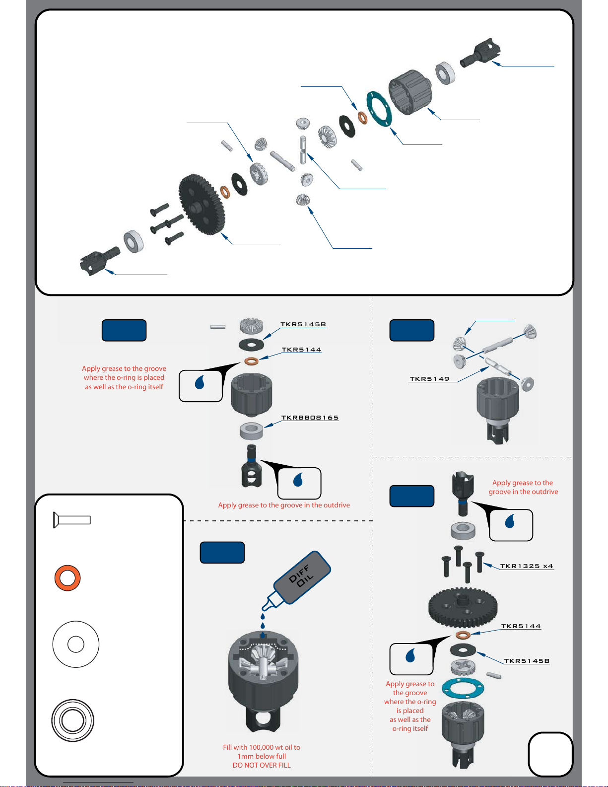
Apply grease to the groove
where the o-ring is placed
as well as the o-ring itself
Apply grease to
the groove
where the o-ring
is placed
as well as the
o-ring itself
Apply grease to the groove in the outdrive
Apply grease to the
groove in the outdrive
Fill with 100,000 wt oil to
1mm below full
DO NOT OVER FILL
TKR5145B
TKR5144
Bag A
Center Differential
(overview)
TKR5237K
TKR5149
TKR5150
TKR5150
TKR5143
TKR5113
*TKR5237
*TKR5115
(Option)
TKR1325
M3x14mm Flat Head Screw
x4
TKR5144
TKR5145B
TKRBB08165
Ball Bearing(8x16x5mm)
x2
TKR5144
Differential 0-rings
x2
TKR5145B
Differential Shims (6x17mm)
x2
TKR1325 x4
TKR5149
TKRBB08165
Diff
Oil
TKR5114XB
TKR5114XB
TKR5150
TKR5144
3
Grease
Grease
Grease
Grease
Step
A-2
Step
A-1
Step
A-4
Step
A-3
*TKR5149A
(Option)
*
TKR5149A
(Option)

Apply grease to the groove
where the o-ring is placed
as well as the o-ring itself
Repeat for rear di
Fill FRONT with 100,000 wt oil
Fill REAR with 50,000 wt oil
to 1mm below full
DO NOT OVER FILL
Repeat for rear di
Repeat for rear di
Repeat for rear di
*TKR5149A
(Option)
Apply grease to the groove in the outdrive
TKR5145B
TKR5144
TKRBB08165
Grease
Grease
TKR5149
TKR5150
*
TKR5149A
(Option)
Diff
Oil
Apply grease to
the groove
where the o-ring
is placed
as well as the
o-ring itself
Apply grease to the
groove in the outdrive
Bag B
Front and Rear Differential
(overview)
TKR5403
TKR5149
TKR5150
TKR5150
TKR5143
TKR5113
TKR1325
M3x14mm Flat Head Screw
x8
TKR5144
TKR5145B
TKRBB08165
Ball Bearing(8x16x5mm)
x4
TKR5144
Differential 0-rings
x4
TKR5145B
Differential Shims (6x17mm)
x4
TKR1325 x4
TKR5114XB
TKR5114XB
TKR5143
TKR5144
4
Grease
Grease
Step
B-2
Step
B-1
Step
B-4
Step
B-3
TKR5012
TKR5012
TKR5028
TKR5075 TKR5405
Front
Inner Bulkheads
Rear
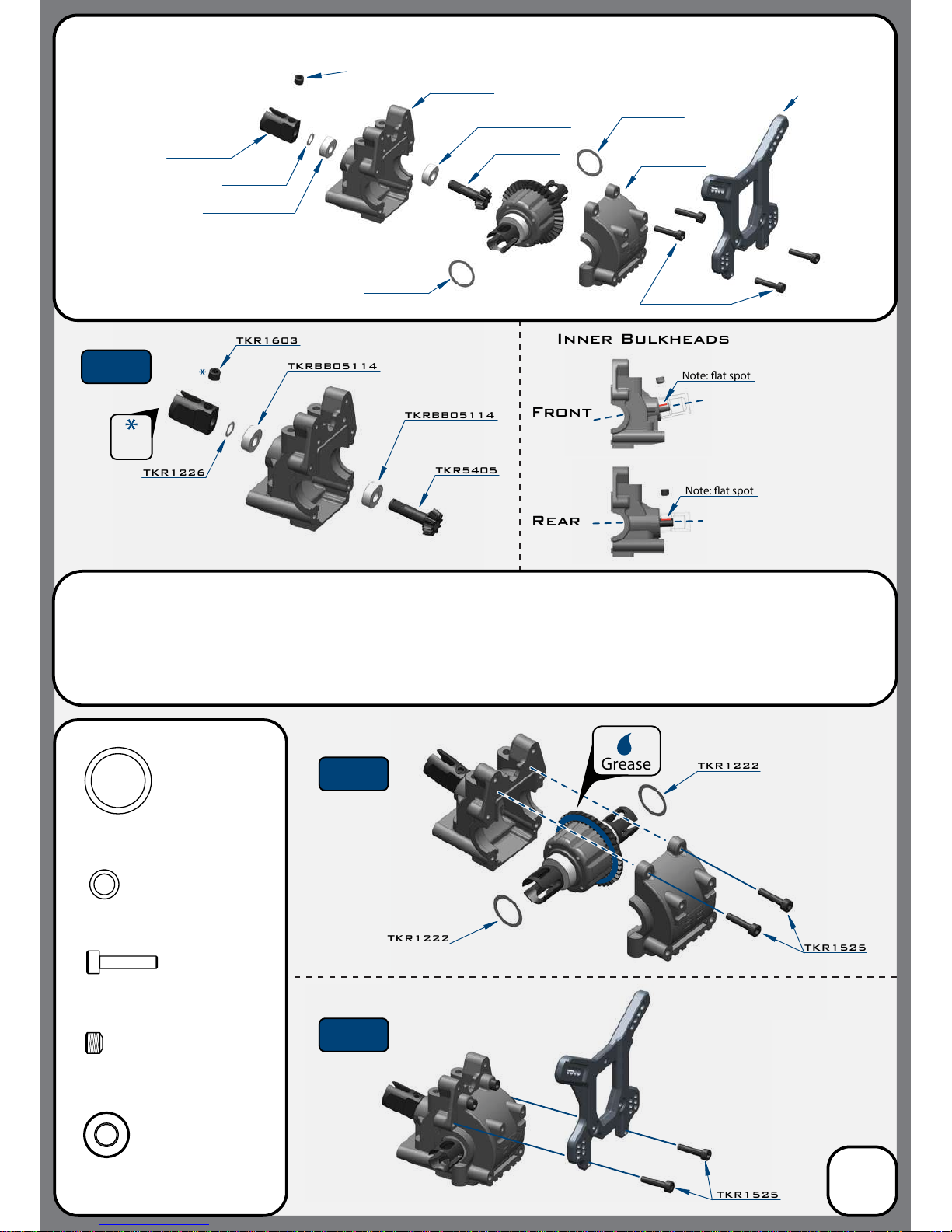
TKR1603
TKRBB05114
TKRBB05114
TKR5405
TKR1222
TKR1222
TKR1525
TKR1222
TKRBB05114
TKR1222
TKR1525 x4
TKR1226
TKR1226
TKRBB05114
TKR1525
TKR1525
M3x14mm Cap Head Screw
x4
TKRBB05114
Ball Bearing (5x11x4)
x2
x2
TKR1222
13x16x0.1mm Diff shim
TKR1603
Note: at spot
Note: at spot
TKR1603
M5x4mm Set Screw
x1
Grease
Bag C
Front Gearbox
(overview)
Step
C-1
Step
C-2
Step
C-3
5
Thread
Lock
TKR1226
5x7x0.2mm shim
x1
Note: Step C-2 To properly shim the di, you will start by test tting the di with no shims and check for
side to side play. If no (or very little) play is present, then continue on to the next step. If you feel
excessive side to side play, then start by adding one shim on the gear side of the di assembly. This
will move the mesh tighter and remove any play. If the mesh is too tight at this point, move the shim
to the other side. In some rare cases, two shims may be necessary.
Note: The front and rear of
the car use dierent inner
bulkheads.
The front is angled
whereas the rear is
only slightly angled.
*These may not be needed
*These may not be needed
*These may not be needed
*These may not be needed
TKR5075
TKR5016B
TKR5029
TKR1222
TKR1222
TKR1525
TKR1222
TKR5016B
TKR1525
M3x14mm Cap Head Screw
x4
TKRBB05134
Ball Bearing (5x13x4)
x2
TKR1222
13x16x0.1mm Diff Shim
x2
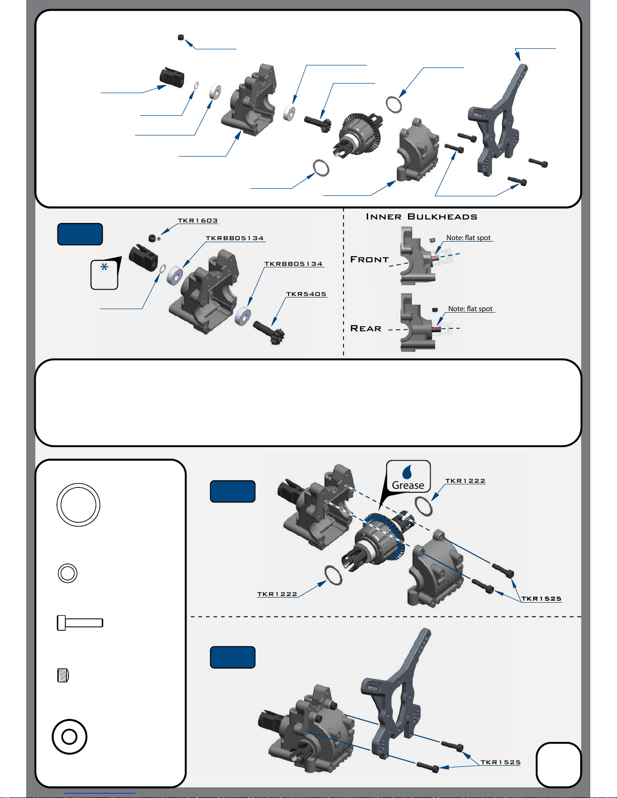
TKRBB05134
TKRBB05134
TKR5405
TKRBB05134
TKR1603
TKR1603
TKR1525TKR1525
Front
Note: at spot
Rear
Note: at spot
TKR1525 x4
TKR1222
TKR1226
TKRBB05134
TKR1603
M5x4mm Set Screw
x1
TKR1226
5x7x0.2mm shim
x1
Grease
Inner Bulkheads
Bag D
Rear Gearbox
(overview)
6
Step
D-1
Step
D-2
Step
D-3
Thread
Lock
Note: The front and rear of
the car use dierent inner
bulkheads.
The front is angled
whereas the rear is
only slightly angled.
*These may not be needed
*These may not be needed
*These may not be needed
*These may not be needed
TKR5405
TKR1226
Note: Step D-2 To properly shim the di, you will start by test tting the di with no shims and check for
side to side play. If no (or very little) play is present, then continue on to the next step. If you feel
excessive side to side play, then start by adding one shim on the gear side of the di assembly. This
will move the mesh tighter and remove any play. If the mesh is too tight at this point, move the shim
to the other side. In some rare cases, two shims may be necessary.
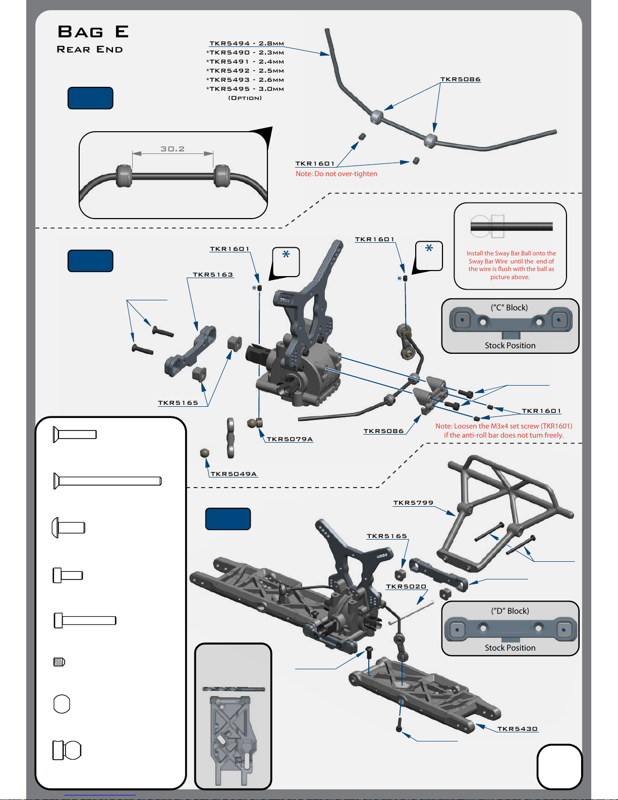
TKR1601
TKR5494 - 2.8mm
TKR5086
Note: Do not over-tighten
Stock Position
(”D” Block)
Stock Position
(”C” Block)
*TKR5490 - 2.3mm
*TKR5491 - 2.4mm
*TKR5492 - 2.5mm
*TKR5493 - 2.6mm
*TKR5495 - 3.0mm
(Option)
30.2
TKR1601
TKR1601
TKR5086
Install the Sway Bar Ball onto the
Sway Bar Wire until the end of
the wire is ush with the ball as
picture above.
Note: Loosen the M3x4 set screw (TKR1601)
if
the anti-roll bar does not
turn freely.
TKR5049A
TKR5020
TKR5163
TKR5165
TKR5799
TKR5430
TKR1601
TKR5079A
TKR5165
Bag E
Rear End
Thread
Lock
Thread
Lock
7
TKR1327
TKR1333
M3x40mm Flat Head Screw
x2
TKR1443
M4x10mm Button Head Screw
x2
TKR5049A
Pivot Ball Sway Bar
x2
TKR5079A
Stabilizer Ball
x2
TKR1522
M3x8mm Cap Head Screw
x2
TKR1529
M3x20mm Cap Head Screw
x2
TKR1327
M3x16mm Flat Head Screw
x2
TKR1333TKR1333
TKR1443
TKR1529
x6
TKR1601
M3x4mm Set Screw
Step
E-1
Step
E-2
Step
E-3
TKR5164
Use a #19 drill bit or
4mm reamer to ream
arms until hinge pin
falls through freely.
Note: With these stock
center dot settings,
Anti-Squat = 2° / Rear Toe = 3°
TKR1522

TKR5472
TKR5073
TKR5070
TKR5073
TKR5034
TKR1601
TKR1201
TKR1201
TKR5165
Grease
Step
F-1
Step
F-2
Changes to the wheelbase have a dramatic eect on handling,
since it shifts the disribution of weight over the rear wheels.
This adjusts traction. By shortening the wheelbase at the rear, you
are placing more weight over the rear wheels.
Changes to the wheelbase also change the amount of sweep the
rear driveshaft will have. More driveshaft sweep creates an eect
similar to anti-squat, where the rear end gets pushed upwards on
throttle. This helps reduce chassis slap when landing jumps on throttle.
(FRONT)
(REAR)
Bag F
Rear Hub/CVA Assembly
8
Thread
Lock
Note: Notch on pin
needs to line up
with set screw.
TKR5199
TKRBB13194
TKRBB08165
TKR5071C
*TKR5199A
*TKR5199B
(Option)
TKR1603
TKR5073
CV Joint Pin
x2
TKR1201
M3 Locknut Black
x4
TKR1603
M5x4mm Set Screw
x2
TKRBB13194
Ball Bearing (13x19x4)
x2
TKRBB08165
Ball Bearing (8x16x5)
x2
TKR5071C
M3x16.8mm Pin
x2
TKR1601
M3x4mm Set Screw
x4
Note: Below the TKR1601 set screws are meant to keep the outer hinge pins from moving. After installing the outer
hinge pins, install TKR1601 in the locations indicated. Very slowly tighten the set screws until you feel some
resistance from contacting the hinge pin. DO NOT OVERTIGHTEN. Also be sure to loosen
TKR1601 before removing the hinge pin or you may damage some parts.

TKR5187
TKR5450
TKR5052A
This side
mounts on hub
Note: no ange
This side mounts
on shock tower
Note: ange
TKR5053A
Actual Size
77.50
Note: notch always goes
on
left side of vehicle
TKR1529
TKR1201
Right
Left
TKR1201
TKR1529
This side mounts
on shock tower
Note: ange
TKR5052A
TKR5053A
This side
mounts on hub
Note: ange
TKR5450
TKR5187
TKR5187
TKR5187
Step
F-3
Step
F-4
Bag F
Rear Camber Links
9
TKR1201
M3 Locknut Black
x4
TKR1529
M3x20mm Cap Head Screw
x4
TKR5053A
Pivot Ball M3x6.8mm
No Flange
x2
TKR5052A
Pivot Ball M3x6.8mm
x2
A
B
C
Stock position is 5/B
D
1
2
34
5
6

TKR1528
M3x18mm Cap Head Screw
x2
TKR1327
M3x16mm Flat Head Screw
x4
Note: “Top” side up
Step
F-5
Step
F-6
Bag F
Rear Bumper
10
TKR1327
TKR1327
TKR1327
TKR5799
TKR1327
TKR5799
TKR1528
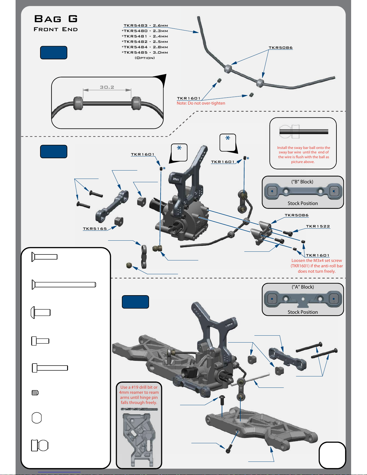
Use a #19 drill bit or
4mm reamer to ream
arms until hinge pin
falls through freely.
Stock Position
(”B” Block)
Stock Position
(”A” Block)
30.2
TKR1601
TKR1601
TKR1601
TKR5086
TKR5483 - 2.6mm
TKR5086
Install the sway bar ball onto the
sway bar wire until the end of
the wire is ush with the ball as
picture above.
Loosen the M3x4 set screw
(TKR1601) if
the anti-roll bar
does not
turn freely.
Note: Do not over-tighten
TKR1601
TKR5165 TKR1522
TKR1522
M3x8mm Cap Head Screw
x2
Bag G
Front End
*TKR5480 - 2.3mm
*TKR5481 - 2.4mm
*TKR5482 - 2.5mm
*TKR5484 - 2.8mm
*TKR5485 - 3.0mm
(Option)
Thread
Lock
Thread
Lock
11
TKR1327
TKR1333
M3x40mm Flat Head Screw
x2
TKR1443
M4x10mm Button Head Screw
x2
TKR5049A
Pivot Ball Sway Bar
x2
TKR5079A
Stabilizer Ball
x2
TKR1529
M3x20mm Cap Head Screw
x2
TKR1327
M3x16mm Flat Head Screw
x2
TKR1333
TKR1443
TKR1529
TKR5020
TKR1601
M3x4mm Set Screw
x6
Step
G-1
Step
G-2
Step
G-3
TKR5162
TKR5161
TKR5436
TKR5056
TKR5049A
TKR5079A
TKR5165
TKR5165
Note: With these stock settings,
Kick Up = 10° / Arm Sweep = 0°
TKR1522
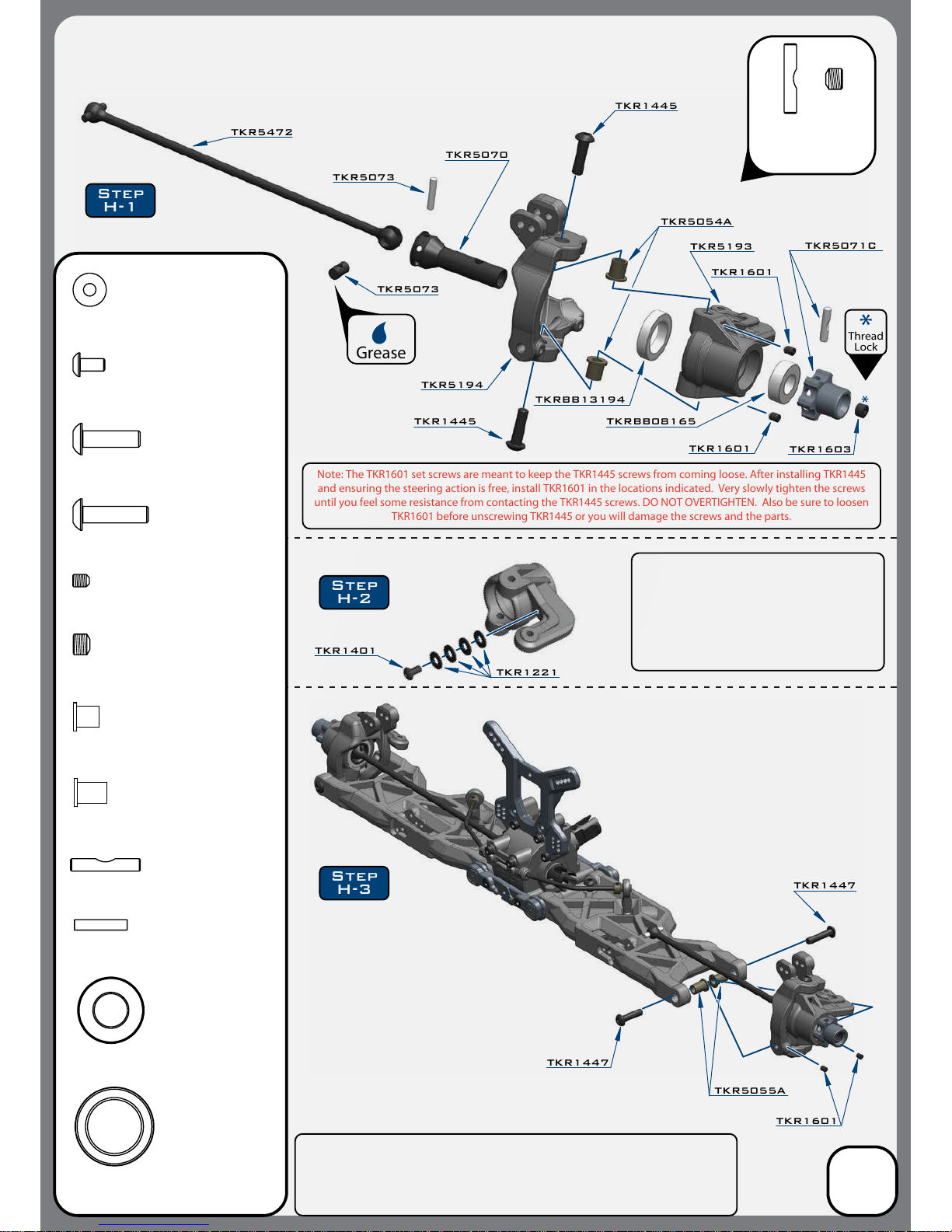
TKR5472
TKR5193
TKR5054A
TKR1445
TKRBB08165
TKR5194
TKR5070
TKR1447
TKR1447
TKR1601
TKR1601
TKR1601
TKRBB13194
TKR1221
TKR1401
TKR1445
TKR5054A
Spindle Pin Sleeve
x4
TKR5055A
Suspension Pin Sleeve
x4
Grease
TKR5073
TKR5073
Step
H-1
Step
H-3
Step
H-2
Thread
Lock
TKR5071C
TKR1603
TKR1445
M4x14mm Button Head Screw
x4
TKR1447
M4x16mm Button Head Screw
x4
TKR5073
CV Joint Pin
x2
TKR1603
M5x4mm Set Screw
x2
TKRBB13194
Ball Bearing (13x19x4)
x2
TKRBB08165
Ball Bearing (8x16x5)
x2
TKR5071C
M3x16.8mm Pin
x2
TKR1601
M3x4mm Set Screw
x8
TKR5055A
TKR1401
M3x6mm Button Head Screw
x2
Note: The TKR1601 set screws are meant to keep the TKR1445 screws from coming loose. After installing TKR1445
and ensuring the steering action is free, install TKR1601 in the locations indicated. Very slowly tighten the screws
until you feel some resistance from contacting the TKR1445 screws. DO NOT OVERTIGHTEN. Also be sure to loosen
TKR1601 before unscrewing TKR1445 or you will damage the screws and the parts.
Bag H
Front Spindle / CVA Assembly
12
Note: notch on pin
needs to line up
with set screw.
TKR1221
M3x8mm Washer
x8
Note: The TKR1601 set screws are meant to keep the TKR1447 screws from coming
loose. After installing TKR1447 and ensuring the steering action is free, install TKR1601
in the locations indicated. Very slowly tighten the screws until you feel some resistance
from contacting the TKR1447 screws. DO NOT OVERTIGHTEN. Also be sure to loosen
TKR1601 before unscrewing TKR1447 or you will damage the screws and the parts.
DO NOT SKIP THIS STEP!
Note: The steering stops provide adjustable
travel limiters to control overall steering throw.
We recommend at least 4 washers on each side.
With too much steering travel
the rear end will lose traction around
corners, the vehicle will be very hard to drive
and it will be more prone to breaking parts.

TKR1529
TKR1201
TKR1529
TKR1201
TKR1201
M3 Lock Nut Black
x4
TKR1529
M3x20mm Cap Head Screw
x4
TKR5052A
Pivot Ball M3x6.8mm
x2
TKR5053A
Pivot Ball M3x6.8mm
No Flange
x2
TKR5187
TKR5451
TKR5187
TKR5052A
TKR5053A
Right
TKR5187
This side
mounts on hub
Note: no ange
This side
mounts on hub
Note: no ange
This side mounts
on shock tower
Note: ange
This side mounts
on shock tower
Note: ange
TKR5187
Left
TKR5451
TKR5053A
TKR5052A
Step
H-5
Step
H-4
64.00
Note: Notch always goes
on
left side of vehicle
Actual Size
Bag H
Front Camber Links
13
Stock position is 4/A
1
2
34
5
6
A
B
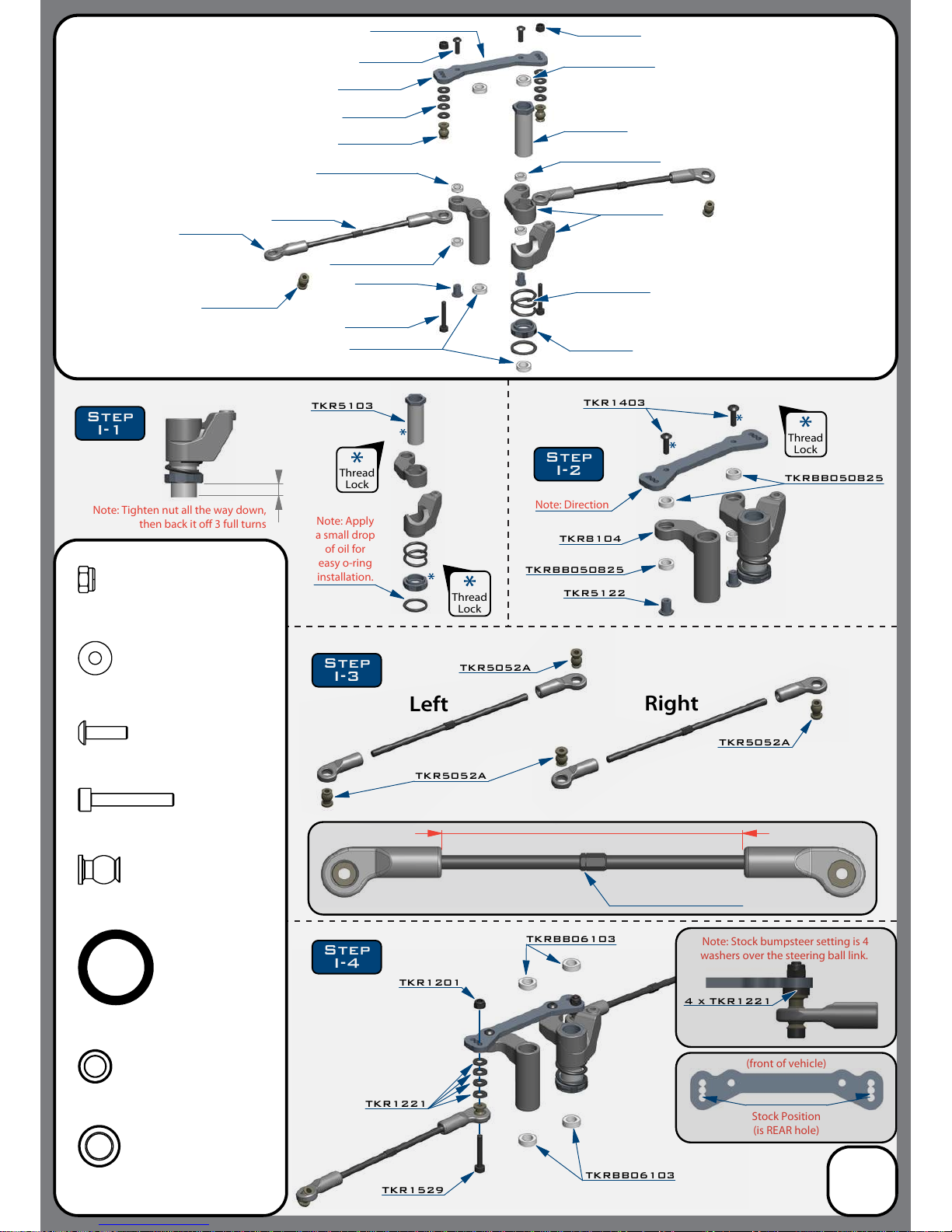
TKR1403
TKRBB050825
TKRBB050825
Note: Apply
a small drop
of oil for
easy o-ring
installation.
Note: Tighten nut all the way down,
then back it o 3 full turns
Stock Position
(is REAR hole)
(front of vehicle)
TKR8100
TKR5056
TKR5424
TKR5052A
TKR5101X
TKR5231
TKR1201
TKRBB06103
TKRBB06103
TKR1529
Note: Stock bumpsteer setting is
4
washers over the steering ball link.
4 x TKR1221
TKR1221
TKRBB06103
TKRBB050825
Note: Direction
TKR8104
TKR5122
TKR8104
TKR1529
TKR5122
TKR1221
TKR8100
TKR1403
TKR5103
TKR5103
TKR1201
TKRBB06103
TKRBB050825
TKRBB050825
TKR5052A
TKR1201
M3 Lock Nut Black
x2
O-ring 16x12x2
TKR5231
x1
TKRBB06103
Ball Bearing (6x10x3)
x4
TKRBB050825
Ball Bearing (5x8x2.5)
x4
TKR1529
M3x20mm Cap Head Screw
x2
TKR5052A
Pivot Ball M3x6.8mm
x4
TKR1221
M3x8mm Washer
x8
TKR5052A
TKR5052A
TKR5052A
Thread
Lock
Thread
Lock
Thread
Lock
Right
Left
Step
I-1
Step
I-2
Step
I-3
Step
I-4
TKR1403
M3x10mm Button Head Screw
x2
Bag I
Steering Assembly
(overview)
14
72.60
Note: Notch always
goes on
the left side of the
vehicle
Actual Size
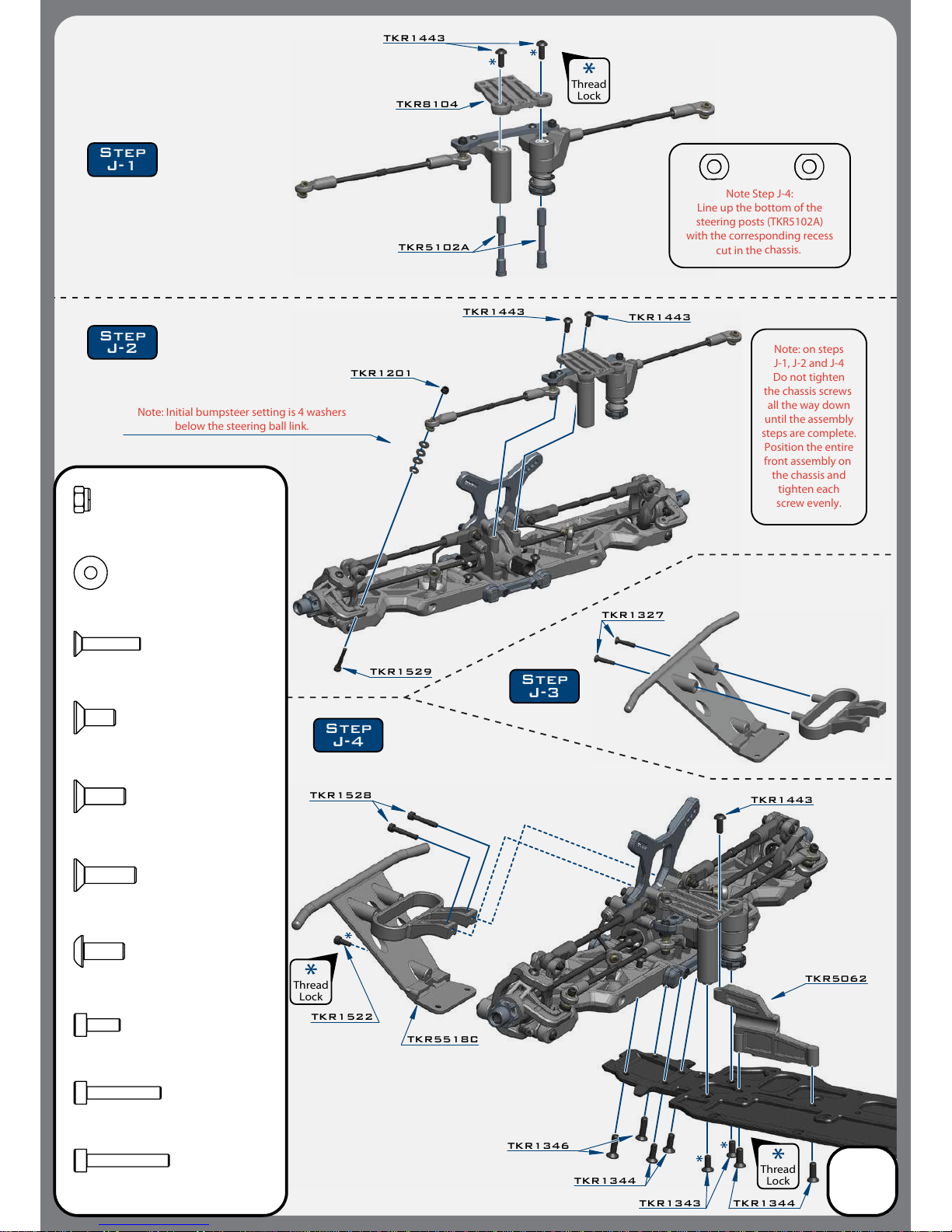
TKR1201
TKR1443
TKR5102A
TKR1443
Note: on steps
J-1, J-2 and J-4
Do not tighten
the chassis
screws
all the way down
until the assembly
steps are complete.
Position the entire
front assembly on
the chassis and
tighten each
screw evenly.
TKR1528 TKR1443
TKR1344
TKR1343
TKR5062
Note: Initial bumpsteer setting
is 4 washers
below the steering ball link.
TKR1327
TKR1344
TKR1346
TKR8104
TKR1443
TKR5518C
TKR1529
TKR1528
M3x18mm Cap Head Screw
x2
TKR1522
M3x8mm Cap Head Screw
x1
TKR1343
M4x10mm Flat Head Screw
x2
TKR1344
M4x12mm Flat Head Screw
x4
TKR1201
M3 Lock Nut Black
x2
TKR1327
M3x16mm Flat Head Screw
x2
TKR1443
M4x10mm Button Head Screw
x5
TKR1529
M3x20mm Cap Head Screw
x2
TKR1221
M3x8mm Washer
x8
Note Step J-4:
Line up the bottom of the
steering posts (TKR5102A)
with the corresponding recess
cut in the
chassis
.
Thread
Lock
Thread
Lock
Thread
Lock
Step
J-2
Step
J-4
Step
J-3
Step
J-1
TKR1522
TKR1346
M4x15mm Flat Head Screw
x2
Bag J
Front End Assembly
15

TKR8104
TKR5263
TKR1522
TKR5191
TKR1443
TKR5062
TKR1344
TKR1343 x5
TKR1445
TKR5062
TKR5076
TKR1344 x5
TKR1524
TKR1522
M3x8mm Cap Head Screw
x2
TKR1524
M3x12mm Cap Head Screw
x4
TKR1343
M4x10mm Flat Head Screw
x5
TKR1443
M4x10mm Button Head Screw
x1
TKR1445
M4x14mm Button Head Screw
x1
TKR1344
M4x12mm Flat Head Screw
x7
Thread
Lock
Thread
Lock
Step
K-1
Step
K-3
Step
K-2
Step
K-4
TKR5263
*TKR5262
(option)
*TKR5262
(option)
TKR5260
Bag K
Center/Rear
Assembly
16
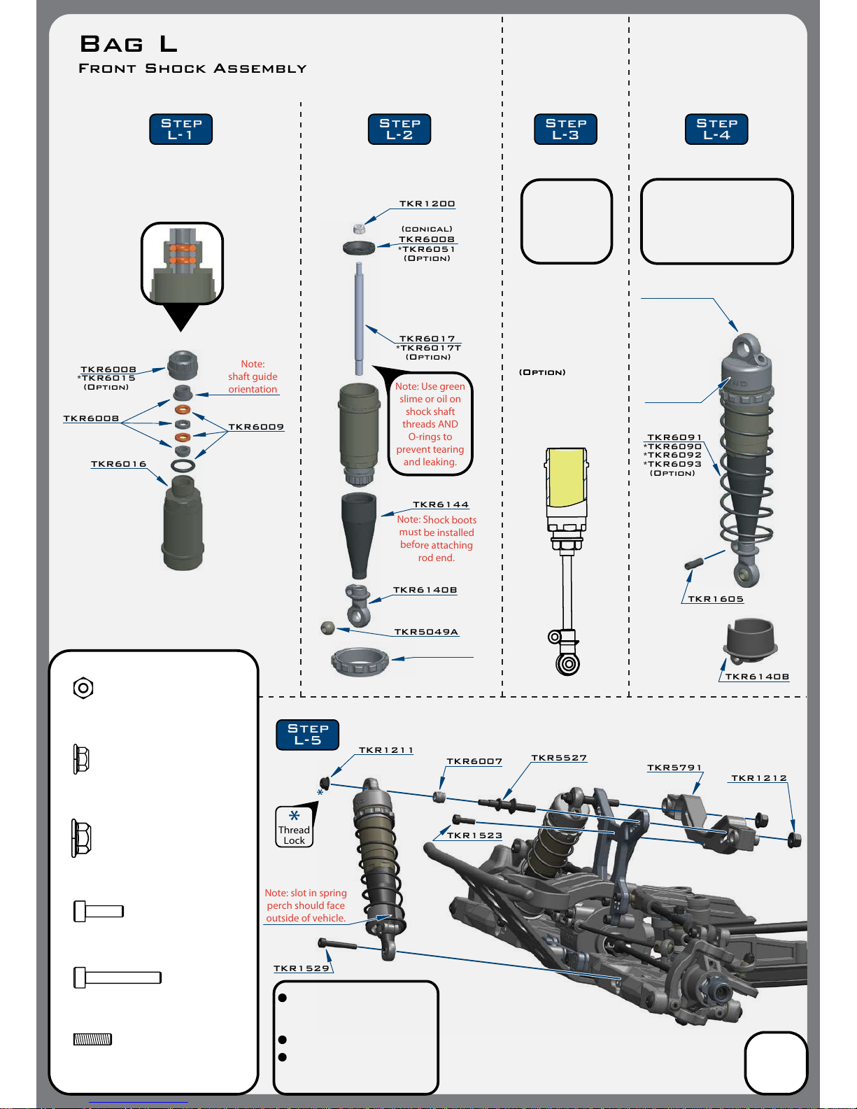
TKR1211
TKR1529
TKR6007 TKR5527
TKR1212
Note: slot in spring
perch should face
outside of vehicle.
TKR1523
TKR5791
TKR6008
TKR6008 TKR6009
TKR6016
M2.5 Lock Nut Zinc
TKR1200
x2
TKR1529
M3x20mm Cap Head Screw
x2
TKR1212
M4 Lock Nut Flange
x2
TKR1211
M3 Lock Nut Flange Black
x2
TKR1200
TKR6008
TKR6017
TKR6140B
TKR5049A
*TKR6017T
(Option)
*TKR6051
(Option)
Note:
shaft guide
orientation
Note: Use green
slime or oil on
shock shaft
threads AND
O-rings to
prevent tearing
and leaking.
TKR6144
*TKR6015
(Option)
Step
L-1 Step
L-2 Step
L-4
Step
L-3
Step
L-5
Note: Shock boots
must be installed
before attaching
rod end.
Thread
Lock
(conical)
TKR6140B
TKR1605
TKR6091
*TKR6090
*TKR6092
*TKR6093
(Option)
(Option)(Option)
Bag L
Front Shock Assembly
17
Stock shock position is outside
hole on the arm and outside
hole on the tower.
Shock length (droop) is 115mm.
Ride height will vary depending
on wheels and tires used.
Start with driveshafts level.
TKR1523
M3x10mm Cap Head Screw
x1
TKR1605
M3x10mm Set Screw
x2
TKR6018
*TKR6003
*TKR6003B
(Option)
Use #700wt oil
FRONT
700
*TKR6013
(Option)
*TKR1213
(Option)
TKR6018
Note:
Make sure to tighten
both cartridge cap (TKR6008)
and shock cap (TKR6018)
to ensure a proper seal.
Tools may be required.
You MUST
drill 1-2mm
(1/16th)
hole here
for bleeder
Refer to lling
instructions on
page 19 during
this step.

TKR1211
TKR1529
TKR6007
TKR5527
TKR1212
Note: slot in spring
perch should face
outside of vehicle.
TKR1212
TKR1523
TKR5791
TKR1605
TKR6008
TKR6008 TKR6009
TKR6060
M2.5 Lock Nut Zinc
TKR1200
x2
TKR1529
M3x20mm Cap Head Screw
x2
TKR1212
M4 Lock Nut Flange
x2
TKR1211
M3 Lock Nut Flange Black
x2
TKR1200
TKR6061
*TKR6061T
(Option)
Note:
shaft guide
orientation
Note: Use green
slime or oil on
shock shaft
threads AND
O-rings to
prevent tearing
and leaking.
*TKR6015
(Option)
Step
M-5
Thread
Lock
Use #700wt oil
REAR
700
TKR6008
*TKR6051
(Option)
(conical)
TKR6140B
TKR5049A
TKR6145
Note: Shock boots
must be installed
before attaching
rod end.
*TKR6013
(Option)
*TKR1213
(Option)
TKR6018
You MUST
drill 1-2mm
(1/16th)
hole here
for bleeder
Step
M-1 Step
M-2 Step
M-4
Step
M-3
TKR6081
*TKR6080
*TKR6082
*TKR6083
(Option)
TKR6140B
Refer to lling
instructions on
page 19 during
this step.
Note:
Make sure to tighten
both cartridge cap (TKR6008)
and shock cap (TKR6018)
to ensure a proper seal.
Tools may be required.
Bag M
Rear Shock Assembly
18
Stock shock position is outside
hole on the arm and 2nd from
outside hole on the tower.
Shock length (droop) is 135mm.
Ride height will vary depending
on wheels and tires used.
Start with driveshafts level.
TKR1523
M3x10mm Cap Head Screw
x1
TKR1605
M3x10mm Set Screw
x2

19
Shock Filling Instructions
For both front and rear shocks
Step 1. Drill a small bleeder hole on the side of all 4 shock caps with a 1-2mm or 1/16” drill bit.
There’s a small dimple on the side of the shock caps over the logo to help guide the bit. Remove the
ashing leftover from drilling, insert bladder and set aside.
Step 2. Extend the shock shaft all the way down. Fill the shock with oil until the body is approximately
95% full.
Step 3. SLOWLY pump the shock shaft up and down 3-5 times to release air bubbles from
underneath the piston.
Step 4. Let the shock rest vertically with the shock shaft fully extended for approximately ve
minutes or until all of the air bubbles have released from the oil.
Step 5. Top o each shock with oil (about 1-2mm below the rim of the shock body). Add a few drops of oil
on top of each bladder inside of the caps. Put a paper towel down to catch excess oil and have another ready
to wipe the shock with. Place the cap on the shock and screw on about half way. Some oil will leak out.
Step 6. Push the shock shaft up to about 90% to set rebound. Some oil will leak out.
Step 7. While holding the shock shaft at 90%, fully tighten the shock cap.
Step
1Step
2Step
3Step
4Step
5Step
6Step
7
We've found it's easiest to complete steps 1 through 4 on each shock before moving onto step 5.
By the time you've nished step 4 on the last shock the rst one will be ready for step 5.
Up and down
3-5 Times
Fill with oil Let rest about
5 minutes
Screw on cap
about half way
Push shaft up
Tighten cap
Drill with
1-2mm
(or 1/16th)
Drill Bit
AND
Insert bladder

TKR5060
TKR5065
Steering servo (not included)
TKR1525
Electronic Speed Control (not included)
double sided tape
TKR5065
TKR5125
Note: Install ESC tray on the
mudguard (do not overtighten)
.
Note: CA glue 3 black o-rings (TKR5125) to the bottom legs of the ESC tray.
TKR1322
TKR1525TKR1525
TKR5065
TKR5065
TKR5065
TKR1401
TKR1322
TKR1322
TKR1401
Receiver (not included)
TKR1401
M3x6mm Button Head Screw
x6
TKR1322
M3x8mm Flat Head Screw
x5
TKR1525
M3x14mm Cap Head Screw
x6
TKR5125
O-ring 3x7mm
x3
TKR1221
M3X8mm Washer
x4
TKR1221
TKR1221
Note: Feed the servo wire underneath the esc tray
in between the mounting screws on the mud guard,
then feed both ESC and servo wires into the RX
box as shown. I
nstall wire retainers (TKR5065)
to secure them properly.
CA
glue
Step
N-4
Step
N-3
Step
N-1
Step
N-2
Bag N
Final Assembly
20
*TKR5060C
(Option)
Table of contents
Other Tekno RC Toy manuals


Popular Toy manuals by other brands


Mega Bloks
Mega Bloks SABAN'S POWER RANGERS SUPER MEGAFORCE Legendary Megazord... instructions

Virtavia
Virtavia F-105D Thunderchief user manual

Black Horce Model
Black Horce Model PZL 104 Wilga Instruction manual book

Mattel
Mattel M8288 instructions

Fisher-Price
Fisher-Price STARRY NIGHT MOBILE 73458 instructions

LeapFrog
LeapFrog Lettersavrus Parent guide & instructions

Eduard
Eduard BAe Nimrod exterior and surface panels quick start guide

Thames & Kosmos
Thames & Kosmos 553013 instruction manual

Mattel
Mattel Barbie BJX85 instructions

Mattel
Mattel Fairytoria L6860 instructions

Mattel
Mattel Barbie CKB57 instructions

Fisher-Price
Fisher-Price Power Wheels CDY14 owner's manual