Teknobil Thuraya Vehicle Docking Adaptor Guide

Thuraya
Vehicle
Docking
Adaptor Installation
Manualand
UserGuide

Teknobil, Teknobil Next, Teknobil Next Thuraya VDA,
Thuraya Manager and SVTS are trademarks of Teknobil A.S.
Thuraya is a trademark of Thuraya Satellite Telecommunications Company.
Microsoft and Windows are trademarks of Microsoft Corporation.
April 2003
Information in this document is subject to change
without notice. Please refer to Teknobil web site at
www.teknobil.com.tr for the latest information
on your product.
Thuraya
Vehicle
Docking
Adaptor Installation
Manualand
UserGuide
ADVANCED TECHNOLOGY SOLUTIONS AND ACCESSORIES FOR ALL YOUR NEEDS
SPECIALLY DESIGNED FOR THURAYA

Introduction
By purchasing the Teknobil Next Vehicle Docking Adaptor (VDA), you have made an excellent
choice toward getting the best from your Thuraya phone on the move. We appreciate your
business, and we would like your experience with Teknobil Next VDA to be as smooth and
beneficial as possible.
In view of the advanced technology involved, we strongly recommend professional installation
by a qualified auto electrician. This installation guide has been prepared to provide the basic
information necessary to install the Teknobil Next Thuraya VDA. The information given is for
general guidance and future reference.
Warning Please read this manual thoroughly before proceeding with the installation
of your unit and pay special attention to the Important Legal and Safety Notices.
Warning As a state-of-the-art accessory, Teknobil Next Thuraya Vehicle Docking
Adapter(ThurayaVDA)isdesignedtobefullycompatiblewithThurayaphonesoftware
version 12.11.2001 and newer. If in doubt, type *#9999# on your Thuraya phone to
reveal its software version which will show at the bottom of the screen. If the software
version of your Thuraya phone is older than the specified date, you may experience
compatibility problems when using it with the VDA, and hence you are strongly
recommendedtotakeyourThurayaphonetoyoursupplierforafreesoftwareupgrade.
32
Tableof Contents
INTRODUCTION 3
FEATURES 4
COMPONENT PARTS 5
INSTALLATION 7
Before You Install 7
Where to Install 8
Mounting the External Antenna 8
Installing the VDA Holder 9
Installing the Control Box 10
Installing the Privacy Handset 13
Installing Hands-Free Microphone 13
Installing the Hands-Free Speaker 14
Testing the Installation 15
OPERATION 16
Getting to Know Your VDA Holder 16
Turning on Your Unit for the First Time 17
Making Calls With the Handset 19
Making Calls With in the Hands-Free Mode 20
Sending SMS Messages 20
Data, Fax and Internet Connections 20
Optional Thuraya Manager Software 22
OPTIONAL SMART VEHICLE TRACKING SYSTEM (SVTS) 23
Fleet Management Features of Thuraya VDA when Used with SVTS 23
The SVTS Control Center 24
TECHNICAL SPECIFICATIONS 26
Electrical Specifications 26
Mechanical Specifications 26
IMPORTANT LEGAL AND SAFETY NOTICES 27
WARRANTY CARD 29

5
4
Your unit extends the seamless connectivity provided by your Thuraya phone to vehicles on
the move. Enriched with features that are designed to make your journeys more comfortable
than ever, your Thuraya VDA will become an indispensable part of your life.
The main features of your unit are the following:
•Full duplex hands-free voice communication
•Unlimited talk time using DC power supplied by your vehicle's
battery
•Privacy handset
•Compatibility with both GSM and satellite modes
•Acquiring GPS data in the vehicle
•Charging Thuraya phone’s battery
•Computer port for data communication and Internet access
•Car radio mute
•Works with both Hughes & Ascom Phones
•Vehicle tracking (optional)
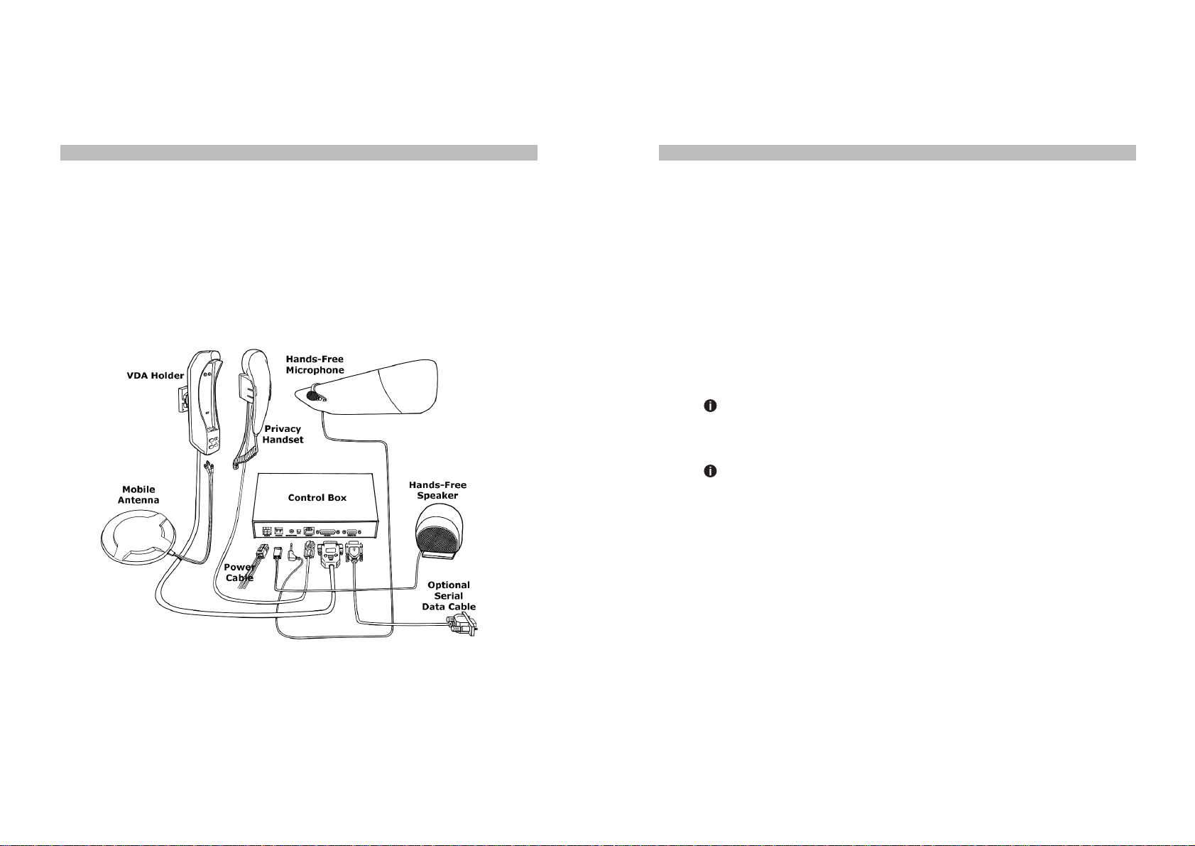
Carefully unpack the equipment and ensure that all component parts are present. If any
component part is missing, please do not proceed with installation and contact your local dealer
immediately. The main parts of your unit are shown in Figure 1.
Control Box
Houses the electronic circuitry of your unit. By using your vehicle's power supply, provides the
power necessary for the operation of the VDA and for charging your Thuraya phone.
VDA Holder
Ensures that your Thuraya phone is firmly docked into the VDA. You can adjust the Control
Box settings by using the buttons on the VDA Holder.
Mobile (SAT, GSM & GPS) Antenna
Your Thuraya phone, when docked into the VDA, can communicate with the Thuraya satellite
and GSM 900 networks, and receive GPS signals by using this external antenna. The mobile
antenna cable is 2.75 meters long.
Privacy Handset
Usethiswhenyouneedprivacy, rather than talking in hands-free mode, during a call. Connected
to the Control Box Handset Jack.
Hands-Free Speaker
When driving or in other situations you can use the Hands-Free Speaker. Connected to the
Control Box Speaker Jack.
Hands-Free Microphone
Picks up and conveys your voice in the best way. Connected to the Control Box Microphone
Jack.
Mounting Unit
Used to attach the VDA Holder to your vehicle's interior.
Power Cable
Connected to the control box via a 4-pin connector which has the following 3 leads:
•Fused red lead should be connected to the positive (+) terminal of your vehicle's battery.
•Black lead ground (GND) should be connected to a clean, unpainted part of your vehicle.
•White lead should be connected to the car radio mute signal input if that is available.
ComponentPartsFeatures
7
6
Fuse
Should be connected between the battery and the red lead of the Car Interface Cable. For
maximum safety, place the fuse as close to the battery as possible.
Mounting Legs
Used to fix the Control Box to the interior of your vehicle.
FIGURE 1 Main Components of Your VDA
Before You Install
Please read the Safety Precautions carefully and strictly adhere to the following points:
•Professionalinstallationof yourVDAbya qualifiedautoelectricianisstronglyrecommended.
In other words, unless you have a very good reason, you must use professional help
for installation.
•If your vehicle has airbags, make absolutely sure that airbag deployment area is free
of any objects including installed or portable equipment. As airbags inflate instantly and
with great force, improper installation of portable components of your unit could result
in serious injury if an airbag inflates in such a case.
•Use the supplied fuses for wiring.
Warning Your unit runs on a negative ground 12V electrical system. Connecting
yourunittoapower supply withdifferentvoltageor polarity candamageyourequipment.
Most trucks have 24V DC supplies. In such cases, you must seek professional help
to obtain 12 V DC power supply for your VDA.
Warning Make sure the supplied fuse is properly installed. Otherwise, you may
risk fire in the unlikely event of a short circuit in the system.
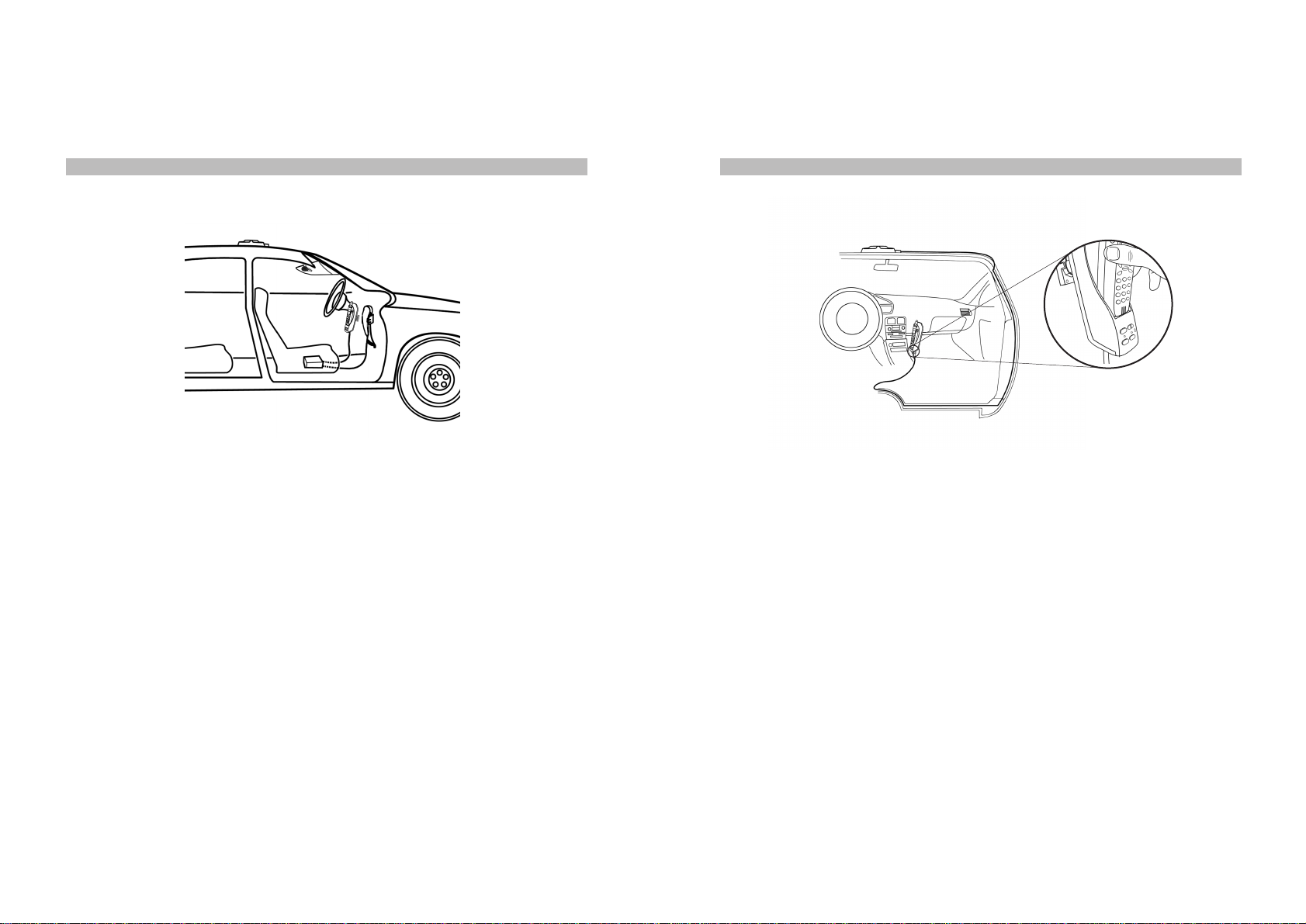
The installation of VDA components may vary according to the make and model of your car.
Suggested positioning of the components is show in Figure 2:
Installation
9
8
Mounting the External Antenna
The External Antenna is required for satellite communication when the Thuraya phone is used
insidea vehicle. The antenna shouldbe mounted on the roofof the vehicle with anunobstructed
view of the sky. You can attach it to the roof of the vehicle using the built-in magnets. Please
refer to Figure 3 for recommended cable routing for the External Antenna.
The External Antenna has a magnetic base and it is connected to the VDA holder with a thin
and flexible triple coaxial cable. This is to allow you to remove the antenna easily and put it in
the vehicle in case you need to park your vehicle in an area where you do not feel safe to keep
the antenna outside the vehicle. You can easily re-route the cable through the door and put
the antenna back on if you need to remove the antenna temporarily. A normal automobile door
with rubber sealing will not harm your cable if it is routed with care.
FIGURE 2 Positioning of VDA Components in Your Vehicle FIGURE 3 Cable Routing for the External Antenna
Take your time to find the best cable route for your vehicle then connect the cables to the
indicated connectors on the Holder:
•Red lead to the GPS connector
•Black lead to the GSM connector
•White lead to the Satellite connector
Caution
The External Antenna is designed for optimal performance when installed on the roof
of your vehicle. If it is mounted on the trunk or a lower surface, satisfactory performance
may not be possible.
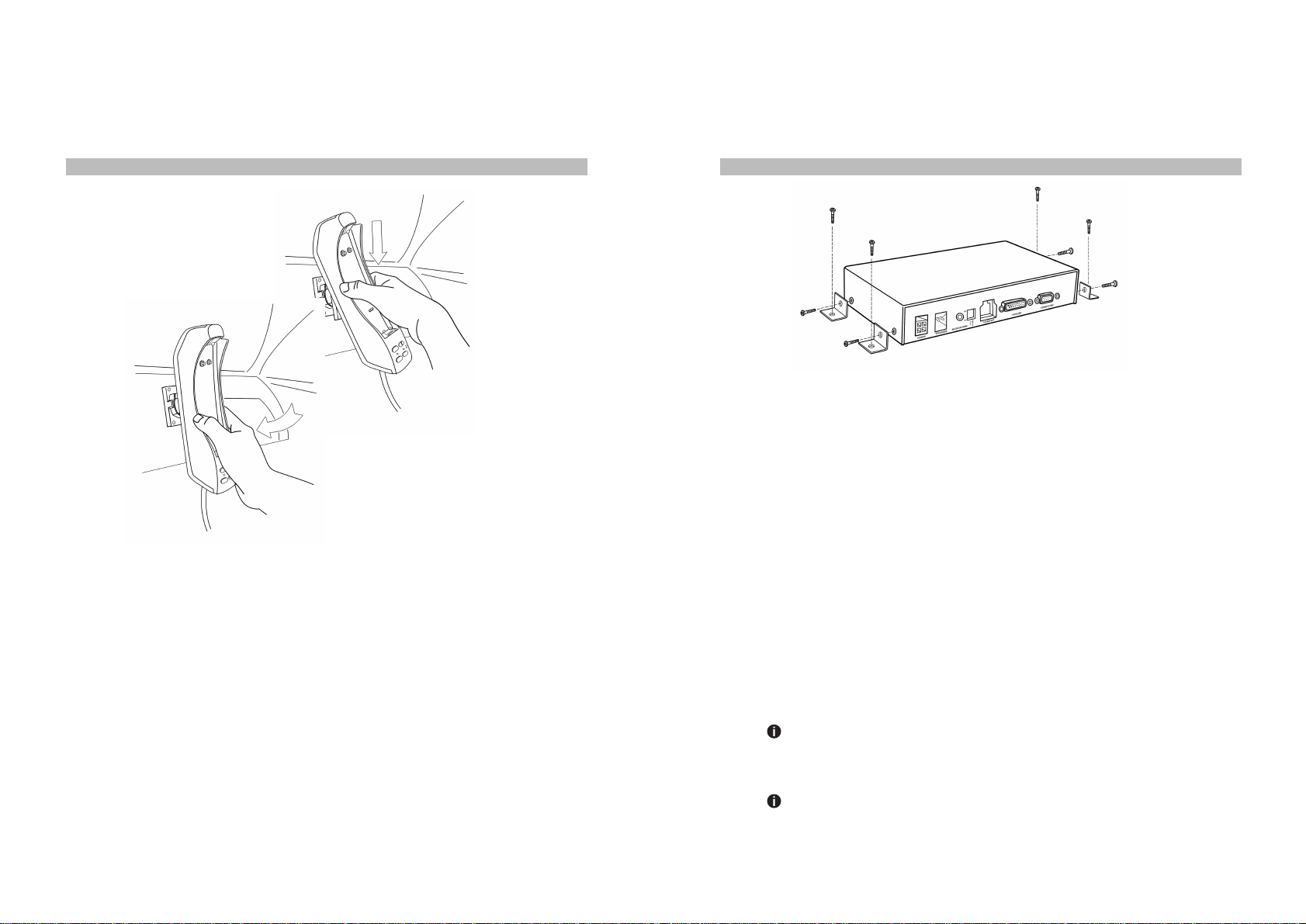
Installing the VDA Holder
You may install the VDA Holder anywhere in the front section of the vehicle by fixing the
Mounting Unit. The Mounting Unit must be fixed to the interior of your vehicle firmly. Ensure
that the driver can easily reach the keypad. Figure 4 shows how to mount the VDA Holder
on the Mounting Unit.
11
10
Installing the Control Box
The Control Box can be placed under the seat or any safe place. Using the mounting legs
fasten the control box tightly to the vehicle’s interior as shown in Figure 5.
FIGURE 4 Installing the VDA Holder
FIGURE 5 Installing the Control Box
Follow the exact sequence below for your safety and to avoid any damage to your unit:
•Turn off the ignition and disconnect the vehicle battery.
•Connect the leads to the Control Box and ensure that the Red lead is connected the last.
•After you connect one end of each lead to the Control Box, refer to Figure 6 and proceed
with the following connections:
°Black lead to a clean, unpainted metallic part of your vehicle for proper grounding.
°White lead to the mute input of your car audio system, if applicable.
°Red lead to the positive terminal of your vehicle's battery.
°Microphone and the Speaker to the Control Box.
°Holder cable to the Control Box.
°Privacy Handset to the Control Box.
°Car interface cable to the Control Box.
The above instructions describe how to power your Control Box from your vehicle's battery.
In this case, your unit will operate, charge your Thuraya phone and thus consume power
regardless of whether your car is running or not. Alternatively, you may prefer to power your
Control Box from the ignition switch. In this case, your unit will operate, charge your Thuraya
phone and consume power only when the ignition is ON.
Warning Your unit runs on a negative ground 12V electrical system. Connecting
yourunittoapowersupplywith differentvoltageorpolaritycandamageyourequipment.
Most trucks have 24V DC supplies. In such case, you must seek professional help
to obtain 12 V DC power supply for your VDA.
Warning Make sure the supplied fuse is properly installed. Otherwise, you may
risk fire in the unlikely event of short circuit in the system.

13
12
Cable Routing
• Ensure that all connections are firm and stable.
• Ensure that cables will not interfere with or will not be damaged by moving parts in your
vehicle.
• If possible, use existing slots and channels in the vehicle for connection.
• Route the cables so that they will not tangle or interfere with the movement of seats, pedals,
and emergency brakes.
• Avoid routing cables under floor mats in foot traffic areas so they will not get entangled with
your feet.
• Route the cables so that they will not cause electrical interference.
•Be sure to cut the car interface cable to the necessary length, and then install the fuse
holders where they are easily accessible.
Caution – Power Limits
Exceeding the following input voltage and current values causes the power fuse to open and
it will have to be replaced:
• Maximum input voltage: 14 volts
• Maximum input current: 1.5A
FIGURE 6 Control Box Connection Diagram
Installing Hands-Free Microphone
The hands-free microphone must be placed as close to the driver’s mouth as possible (30–35
cm) and point directly to the mouth. A recommended location for the microphone is above the
sun visor as shown in Figure 8. It is not recommended to place the microphone on the steering
wheel or on the dashboard. The microphone should be firmly fastened for best sound quality.
Route the microphone cable and secure it with commercially available tape so that it will not
interfere with driving.
InstallingthePrivacyHandset
Using the two screws fasten the handset tightly to a flat surface in the vehicle as shown in
Figure 7.
FIGURE 7 Installing the Privacy Handset

15
14
FIGURE 8 Installing the Hands-Free Microphone above the Sun Visor
Installing the Hands-Free Speaker
Ensure that the speaker is at least 80 cm away from the microphone to ensure that the voice
is echo-free. Do not place the speaker behind any lining as this may reduce the speaker
volume. To fasten the speaker, refer to Figure 9 and do the following:
• Detach the speaker from the bracket.
• Secure the bracket to an appropriate flat surface in the vehicle using four screws.
• Remount the speaker onto the bracket.
Testing the Installation
Your VDA is a high-technology product enabling in-vehicle use of your Thuraya phone and
bringing many features to your Thuraya experience. For your unit to work satisfactorily and
not to impair the driver or your car, please ensure that you fully test it after installation.
For this purpose, start your vehicle and ensure that you hear the sound of the engine working
normally. Check brake lights, headlights, air conditioning and windshield wipers to see that
they operate properly with the VDA installed.
Use the Thuraya phone to make a call when the vehicle is parked and the engine is running.
During the call, switch off the engine. Ensure that Thuraya phone operates with the engine
running and with the engine turned off. For information about using your Thuraya phone, refer
to the Thuraya phone user guide.
Check that the Car Interface Cable and the External Antenna Cable do not interfere with
opening and closing the doors and the trunk, or with moving the sun visor, steering wheel,
brakes, gear shift or seats.
Ensure that all components are secured and do not shift when the vehicle is in motion or when
it comes to a stop.
Speaker
Bracket
Figure 9 Installing the Hands-Free Speaker

17
16
Getting to Know Your VDA Holder
Figure 10 shows the location of the buttons and the indicator lights on your VDA Holder.
1. Alarm Button Sends an alarm message to the Control Center if the SVTS dip switch is in
the ON position and if you are an SVTS user. If you are not an SVTS user, when the Alarm
dip switch is set to the ON position, the Alarm button dials the first number in the phonebook
or, in case the phonebook is empty, dials the emergency operator at 112. Please refer to
Table 1 for an explanation of setting the dip switches.
2. Volume Down Button Decreases the volume by one step.
3. Volume Up Button Increases the volume by one step.
4. Power Indicator Red when the VDA is powered; off otherwise.
5. Battery Charging Indicator Red when charging is in process; turns Green when fully charged.
6. Mute Button Temporarily cuts off the Hands-Free and Handset Microphone.
7. Mute Indicator Red light shows Microphone is muted; off otherwise.
8. Mode Selection Button Toggles between hands-free operation and handset operation.
9. Hands-Free Mode Indicator Red light shows Hands-Free Mode; off in the Handset Mode.
1
9
8
23
4
5
6
7
FIGURE 10 Buttons and Indicator Lights on the VDA Holder
Turning on Your Unit for the First Time
Attaching Thuraya phone to the VDA Holder
Warning Failing to remove the rubber dust cap behind Thuraya phone may damage
the VDA Holder. In such a case, your warranty will be void.
•Remove the rubber dust cap behind Thuraya phone.
•Firmly insert the bottom of the Thuraya phone into the bottom of the VDA Holder as shown
in Figure 11.
•Push Thuraya phone toward the VDA Holder until you hear a firm click.
Now you should see message "Vehicle Docking Adapter Connected" on the screen of your
Thuraya phone.
FIGURE 11 Pushing Thuraya phone Toward the Holder
Removing Thuraya phone from the VDA Holder
Using your index finger, gently pull Thuraya phone out of the VDA Holder as indicated by Figure
12.
Operation
19
18
FIGURE 12 Removing Thuraya phone from the VDA Holder
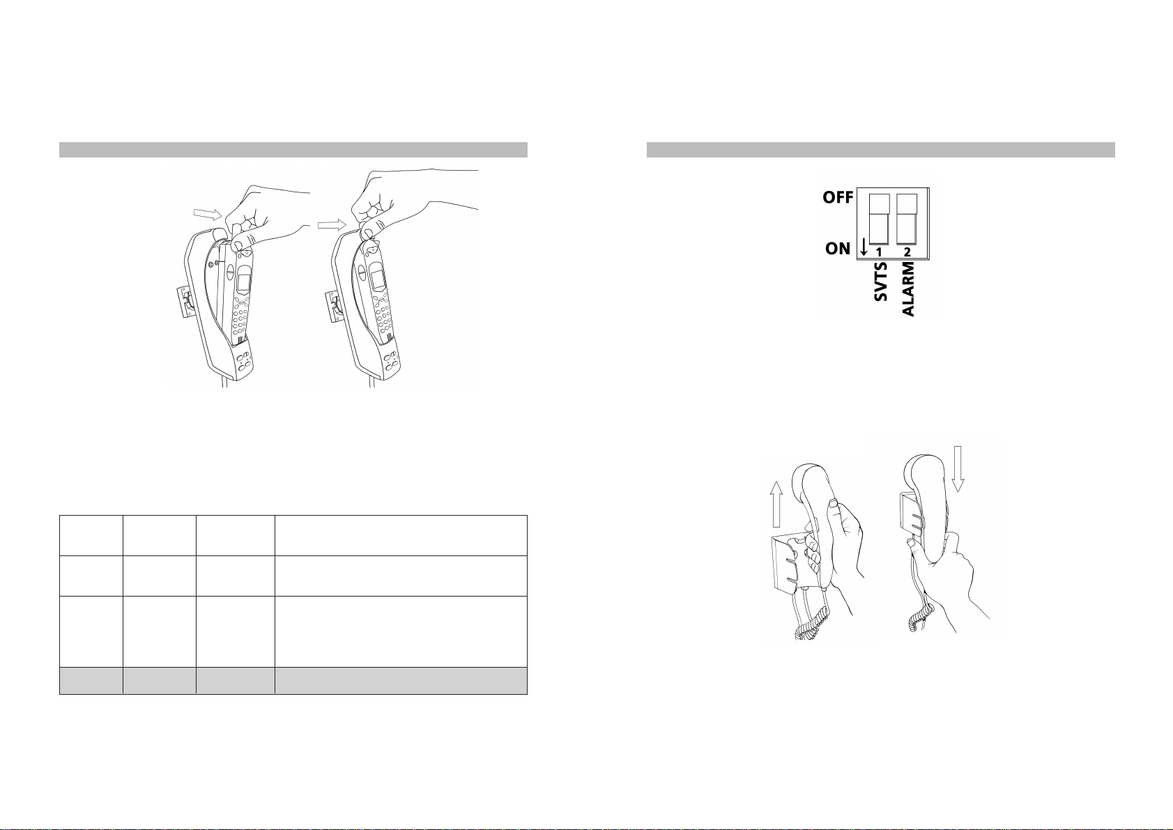
Setting the Smart Vehicle Tracking System (SVTS) and the Alarm Dip
Switches If you are using the optional SVTS service (see The Smart Vehicle Tracking
System), this switch must be in the ON position. Table 1 explains the combined operation
of these two switches that are shown in Figure 13. The shaded row shows the default setting.
STVS
Switch Alarm
Switch SVTS
Enabled Result When the Alarm
Button in Pressed
On
Off
Does not
matter
On
Yes
No
AmessageisautomaticallysenttotheSVTS
Control Center.
VDAcallsthe firstnumberinyourphonebook
is not empty; calls Thuraya’s general
emergency number (112) if it is empty.
Alarm button has no function.Off Off No
TABLE 1 How the SVTS and Alarm Dip Switches Work
FIGURE 13 Setting the SVTS and Alarm Switches
Making Calls with the Handset
Your VDA is in the Handset mode when the Hands-Free indicator is off. If this indicator is red
(ON) and you would like to make a call with the Handset, simply press the Mode Button to
switch to the Handset mode.
FIGURE 14 Lifting and Replacing the Privacy Handset
Making a Call with the Handset
•Lift the Privacy Handset as shown in Figure 14.
•Dial the number using the keypad of your Thuraya phone.
•Press the Call button on Thuraya phone.

21
20
Answering a Call with the Handset
•Lift the Privacy Handset or
•If the Hands-Free Mode Indicator is OFF, press the Accept button on Thuraya phone.
To End a Handset Mode Call
•Press the End button on Thuraya phone, or
•Replace the Handset.
Making Calls With in the Hands-Free Mode
Your VDA is in the Handset mode when the Hands-Free indicator light is ON. If this indicator
is off and you would like to make a Hands-Free call, simply press the Mode Button to switch
to Hands-Free.
Making a Hands-Free Call
• Dial the number using the keypad of your Thuraya phone.
• Press the Call button on Thuraya phone.
Answering a Call Hands-Free
• Press the Accept button on Thuraya phone.
For your comfort, do not use the Hands-Free mode if the prevailing background noise in your
vehicle makes it difficult for either party to carry out a conversation.
Sending SMS Messages
When docked in the VDA, your Thuraya telephone can send and receive SMS messages
normally. For a more convenient way of sending SMS messages, please refer to the section
of the Thuraya Manager Software.
You can make use of the data features of your Thuraya phone in your vehicle by connecting
a computer to the VDA using a 9 pin RS-232 cable. For this to work, data functions on your
Thuraya SIM card should be enabled. Once the connection is made as described, you will
first need to define your Thuraya phone as a modem under Windows, and then define a new
dial-up network connection.
Adding Your Thuraya Phone as a Modem under Windows 2000
After ensuring that the Thuraya phone is firmly docked in position and a serial cable (not
supplied) is securely fastened to the VDA, follow these steps to configure your Thuraya phone
as a modem:
•Go to Start > Settings> Control Panel>Phone and Modem Options.
•In the Phone and Modem Options dialog window, select the Modems tab and then click
on Add.
•When you invoke the Install New Modem dialog box check the box beside "Don't detect
my modem; I will select it from a list" then click Next.
•Inthedialogwindowthatnowappears,select"StandardModemTypes" in the Manufactures
box and "Standard 19200 bps modem" in the Models box, then click Next.
•When you are asked to select the port you would like to use, choose the port where the
data cable is connected (e.g. COM1), then click Next.
•Windows will now report that the new modem has been successfully installed
•Click Finish to end
Direct Dial-Up Access to the Internet*
Now your computer recognizes Thuraya phone as a modem. All that is left is to make a new
connection that will use the newly introduced Thuraya phone modem.
•Go to Start>Programs>Accessories>Communications>Network Dialup Connections
•Follow the Network Connection Wizard's instructions to make a New Connection
•Select Dial-up to the Internet and click Next
•Choose "I want to setup Internet connection manually" and continue
•Select Connect through phone line and modem, click Next
•Selectthe Standard 19200 bps Modem as the modem thisconnection will use and continue
(*) These instructions are valid for connecting to ISP’s other than Thuraya as well. If you would like to use a connection to a particular ISP,
yo will need to define a similar connection using your ISP’s guidelines with a different set of telephone number, username and
password. For your convenience, a detailed version of these instructions, complete with screenshots, is available on Teknobil’s
web site at www.teknobil.com.tr.
Data,Fax andInternetConnections

23
22
•Enter 1722 in the Telephone Number field and uncheck "Use area code and dialing rules"
if it was checked.
•Supply blank fields for both user name and password when prompted by the wizard.
•Ignore the two warning messages regarding username and password; you need not supply
a username or password for connecting to Thuraya's 1722 service.
•Give a name to your connection e.g. "Thuraya VDA Internet Connection" and click Next
•Click Finish to end.
Your connection is now ready to be used. You may access this connection through Settings
•
Network and Dialup Connections from the Start menu.
Sending and Receiving Faxes
You will need a Class 2.0 fax software to be able to use the fax features of your Thuraya phone
through the VDA. Configure your fax software to use the Standard 19200 bps Modem which
you installed earlier for the Thuraya connection. Use your fax software's normal routines to
send and receive faxes.
Optional Thuraya Manager Software
Developed by Teknobil especially for Thuraya users and available for purchasing separately,
The Thuraya Manager is an indispensable tool making your experience with your Thuraya
phone easier, more comfortable and more effective than ever! By using the Thuraya Manager
you can:
• Read, edit, save and backup your phonebook on Thuraya phone
• Send, receive and save SMS messages with the convenience of your computer's keyboard
• Send multiple SMS messages at one go
• Track your location on a digital map of the world on your notebook
Thuraya Manager runs under Microsoft Windows (98, 2000 and XP). You can download a trial
version of the Thuraya Manager from www.teknobil.com.tr.
OptionalSmartVehicle
TrackingSystem(SVTS)
Your VDA is much more than a simple car kit for your Thuraya phone. The VDA forms the
basis of a full-fledged, Thuraya-based smart fleet management system that can be purchased
from Teknobil separately. All you need to activate the fleet management features of your VDA
is to contact Teknobil.
Once you are subscribed to the SVTS service, you will need to set the SVTS switch in the
Control Box to ON position. If you turn off your SVTS switch, the vehicle cannot be tracked
until the SVTS switch is set to the ON position.
Fleet Management Features of Thuraya VDA
when Used with SVTS
The main piece of information acquired, stored and forwarded by your VDA is the exact location
of your vehicle obtained through GPS. By adding optional data acquisition modules, you can
also have the VDA process and report other information like the temperature in a certain
section of your vehicle, the position of a certain lock or the reading on the fuel gauge. Therefore,
the following fleet management features of your VDA are equally valid for other types of
information as well as position information:
• Send vehicle position and speed to the Control Center via SMS or data link upon request
(polling).
• Send vehicle position in pre-defined periods (e.g. every 15 minutes).
• Record vehicle position and speed in pre-defined periods into the on-board memory.
• Allow the Control Center to download stored information through Thuraya data link.
•Send recorded information to the Control Center in pre-defined periods (e.g. every 24
hours). Thereby feeding the central database with up-to-date information so that full
information from all vehicles is made available to the Control Center for decision support
and other purposes.
• Alert the Control Center and send position information when the Alarm button is pressed.
• Store and forward a record of when it is powered off and when it is powered back on.
• Provide detailed event-based reporting services when the vehicle:
°exceeds the speed limit for a pre-defined period of time
°remains idle more than a pre-defined period of time at any location outside pre-defined
(home) locations
°eaves its given route
°passes through a checkpoint.
°enters or exits a specified region.
25
24
The SVTS Control Center
Your VDA acquires, s tores and forwards all the required information. You also need a Control
Center to receive and process this information from one or more vehicles depending on the
size of your fleet. The Control Center has the following components:
• SVTS software
• Control Center Communication Unit (CCCU)
The CCCU consists of a Thuraya phone and a Thuraya Docker (Fixed Package), and includes
the required satellite and GPS antennas.
ThecommunicationbetweentheSVTSsoftwareintheControlCenterand the VDA is performed
via a pair of CCCU's connected to the server computer. The SVTS software acquires the
information coming from the vehicle units through the CCCU’s, displays the position on a digital
map, and records the information in the SVTS database.
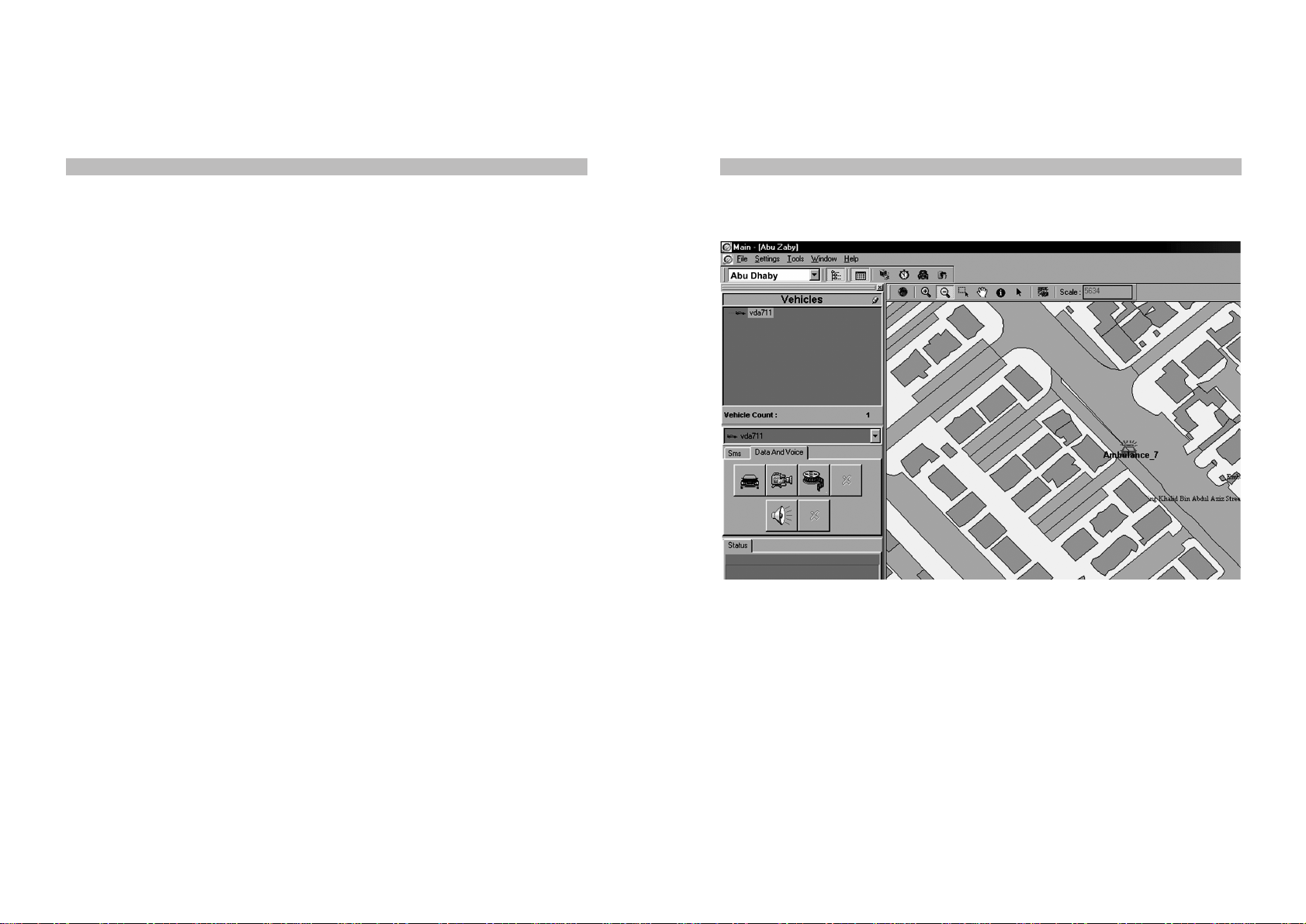
Main Features of the SVTS Software
SVTS has a client-server architecture and thus supports multiple computers and users. To
support possible high traffic requirements of large fleets, the SVTS software is capable of
working with multiple CCCU’s. The system is modular and expandable; adding more vehicles
to the system is a simple task. The following list summarizes the main features of SVTS:
• Capability to remotely set VDA parameters like the data saving and sending period.
• Handling event-based reports coming from VDAs and alerting the System Administrator.
• Displaying vehicle information on digital maps as in Figure 15 either by plotting the current
coordinates or by drawing the routes followed over a specified period.
FIGURE 15 Part of Sample SVTS Screen on Detailed Street Map
27
26
Your unit is fully tested for your safety. However you may still cause serious personal injury
and/or property damage if you do not follow the instructions in this section.
Antenna Care
Useonly supplied Teknobil Next Antenna. Unauthorized antennas, modifications or attachments
could damage your Thuraya phone.
Driving
Check the laws and regulations on the use of wireless telephones in the areas where you
drive. If using your Thuraya phone while driving, please:
• Give full attention to driving
• Use only Hands-Free operation
• Pull off the road and park before making or answering a call if driving conditions require
you to do so.
Pacemakers
You must consult your cardiologist if you wish to use any mobile phone with your cardiac
pacemaker as the various brands and models of pacemakers in the market have different
immunity levels to radio signals. In any case, you are recommended
• to maintain a distance of 15 cm between your pacemaker and your mobile equipment
• not to bring your chest close to the mobile equipment
• to refer to your pacemaker product literature for information on your particular device.
If you have any reason to suspect that interference taking place, turn off mobile phone
immediately!
Hearing Aids
Most new models of hearing aids are immune to radio frequency interference from mobile
phones that are more than 2 meters away. Some are also immune to interference when the
mobile phone is brought up to the same hearing-aided ear. Many types of older hearing aids
may be susceptible to interference, making it very difficult to use a mobile phone. Should
interference be experienced, there are things that can be done which may improve the situation:
• If possible use the mobile phone with your non-aided ear.
• Use Hands-Free function of the Teknobil Next Thuraya Vehicle Docking Adaptor
Important Legal andSafetyNotices
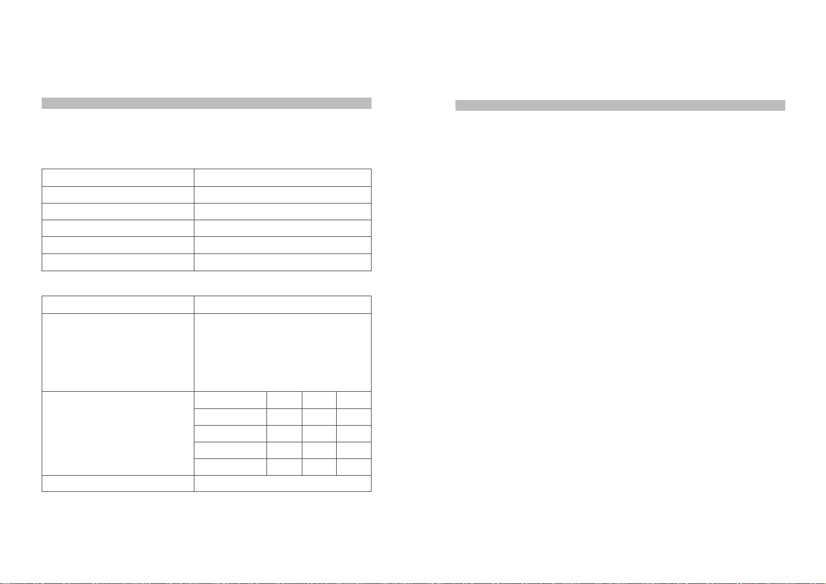
Electrical Specifications
Operating Voltage 12 VDC nominal (min 11VDC / max 14VDC)
Stand-by Current 80 mA max (without charging)
Operating Current 1.5A max (including charge current)
Operating Temperature Range -20 to +55ºC
Storage Temperature Range -55 to +85ºC
Audio Power Output 7W max (to speaker)
Mechanical Specifications 3 x RF connectors (SMA female)
Power connector
Speaker connector
Microphone connector (mono jack)
Handset connector (RJ-45)
Computer RS-232 port (DB-9)
Holder port (DB-26)
(cm) L W H
Control Box 19.5 11.2 3.9
Holder 21.5 6 6
Speaker 8.5 7.5 6.5
Handset 17.5 4.5 4
2.2 kg
Connectors on Holder
Connectors on Control Box
Dimensions
Total Weight
Technical Specifications

Vehicles
RF signals may affect improperly installed or inadequately shielded electronic systems in motor
vehicles. Check with the manufacturer or its representative regarding your vehicle. You should
also consult the manufacturer of any equipment that has been added to your vehicle.
Posted Facilities
Turn your phone OFF in any facility where posted notices require you to do so.
Blasting Areas
Never use the mobile phone where blasting work is in progress. Observe all restrictions and
follow any regulations or rules. Areas with a potentially explosive environment are often, but
not always, clearly marked. Do not use the mobile phone while at a filling station. Do not use
near fuel or chemicals.
For Vehicles Equipped With an Airbag
Do not place objects, including either permanently installed or portable mobile phone in the
area above the airbag or in the airbag deployment area. If an in-vehicle mobile phone is
improperly installed and the airbag inflates, it could result in serious injury.
Limitation Of Teknobil's Liability
TOTHEMAXIMUMEXTENTPERMITTEDBYAPPLICABLELAW,INNOEVENTWILLTEKNOBIL,
ITS SUPPLIERS OR RESELLERS BE LIABLE FOR ANY INDIRECT, SPECIAL, INCIDENTAL,
CONSEQUENTIAL, OR PUNITIVE DAMAGES ARISING OUT OF THE USE OF OR INABILITY
TO USE THE PRODUCT OR CONTENT, INCLUDING, WITHOUT LIMITATION, DAMAGES FOR
LOSS OF GOODWILL, WORK STOPPAGE, COMPUTER FAILURE OR MALFUNCTION, OR
ANY AND ALL OTHER COMMERCIAL DAMAGES OR LOSSES, EVEN IF ADVISED OF THE
POSSIBILITY THEREOF, AND REGARDLESS OF THE LEGAL OR EQUITABLE THEORY
(CONTRACT, TORT OR OTHERWISE) UPON WHICH THE CLAIM IS BASED. THE BUYER
OR USER AGREES WITH PURCHASING THIS PRODUCT THAT HE or SHE MAY NOT
RECOVER ANY AMOUNT FOR INCIDENTAL OR CONSEQUENTIAL DAMAGES, INCLUDING
LOSS OF PROFIT, LOSS OF YIELD AND AMOUNTS EXPENDED IN USING OR TRADING
THIS PRODUCT. THIS LIMITATION OF LIABILITY SHALL BE APPLICABLE TO ANY CLAIM
PRESENTED TO TEKNOBIL WHETHER THE LEGAL THEORY FORMING THE BASIS OF
SUCH CLAIM INVOLVES CONTRACT, TORT, NEGLIGENCE, STRICT LIABILITY OR
OTHERWISE. IF THIS PRODUCT IS PROVED TO BE DEFECTIVE, THE EXCLUSIVE REMEDY,
AT TEKNOBIL'S OPTION, SHALL BE TO REFUND THE PURCHASE PRICE OF OR TO REPAIR
OR REPLACE THE DEFECTIVE PRODUCT. THE BUYER AND USER AGREE THAT IF
TEKNOBIL REFUNDS AN AMOUNT EQUAL TO THE PRICE THE BUYER OR USER PAID
FOR TEKNOBIL’S PRODUCT, THIS LIMITATION OF LIABILITY WILL NOT HAVE FAILED IN
ITS ESSENTIAL PURPOSE. UNDER ANY CIRCUMSTANCES, TEKNOBIL’S LIABILITY WILL
NOT EXCEED THE PURCHASE PRICE OF THE ACCESSORY FROM AN AUTHORIZED
TEKNOBIL DISTRIBUTOR, WHICH WILL BE PROVEN BY PRESENTING A VALID INVOICE. 29
28
One Year Full-Confidence Warranty
This product is guaranteed by Teknobil for one year against manufacturing defects. The
warranty expressly excludes problems caused by misuse or mishandling of the product. If you
feel that your product is not performing properly and it needs to be serviced, contact Teknobil
by mail or E-mail at:
Teknobil International, Ataturk Airport Free Zone
81/A-B, Ofis Plaza No: 923, Bakirkoy, Istanbul, 34830, Turkey
Return postage and insurance are the responsibility of the person returning the merchandise.
Teknobil will return your product postage paid and insured if it is under warranty. Any products
no longer under warranty will be returned at the owner's expense. When returning your
accessory for evaluation and repair, be sure to include your name, address, daytime phone
number and a letter explaining the specific problem you have encountered. Your approval will
be obtained should we need to incur any expenses on your behalf.
Original date of purchase ____ / ____ / ____.
Please mark the Return Authorization Number clearly on every package to be sent to Teknobil!
Indicate on your invoice that you are sending the unit for service and/or repair!
Name
Telephone
Fax
E-Mail
Street Number
City
State/Province
Zip/Postal Code
Customer Seller
Warranty Card

30
Table of contents


