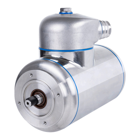
Teknomotor HF Series User guide

S.PRO.27 Rev. 0 del 20.05.08 Pag. 1 di 2
TEKNOMOTOR s.n.c. di Perli Sandro & C.
Via Argenega, 19 32030 Quero (BL)
www.teknomotor.com
MOTORS HF SERIE USE AND MAINTENANCE INSTRUCTION
Conformity with EEC directives.
We declares that our induction motors hf serie and our electrospindles are in accordance with the Low Voltage Directive 73/23/EEC
(revised by the 93/68/EEC Directive). The electric motor, considered like a component, conforms with the 98/37/EEC Machine
Directive. The motor cannot be put into service before the machine into which it is incorporated is declared to be in conformity with
the instructions of the directive 98/37/EEC Art. 4.2 –II B, with our instructions and with the instruction of the directive EN60204-1.
Considering that the motors are powered only by an inverter it is compulsory to attend the instructions of the inverter manufacturer.
Please read these instructions carefully before using the motor; all operations related to the installation, putting into service,
maintenance and protection of the electric motor must be carried out by qualified people only in full observance of all leqal
requirements and applicable technical standards, as well as the safety prescriptions of the EN60204-1 standards governing
electrical equipment for machinery. This documentation integrates and does not substitute any legal requirements, technical
standards or safety prescriptions applicable to the use and maintenance of the electric motor. The manufacturer accepts no liability
for accident or damage resulting from improper use or failure to adhere to applicable EU standards covering the safety of electric
motors.
MECHANICAL INSTALLATION Before installation verify that: the electric motor is not visually damaged (damages due to transport or
storage); the conditions of use and intended application correspond to the indications given on the nameplate; the supply voltage is the
same as network voltage; the ambient temperature is between -20°C e +40°C; the altitude is <1000 meters above sea level (different
conditions of ambient temperature and/or higher altitudes implies a corrective factor of the power); the IP rating indicated on the motor is
suitable for the ambient conditions in accordance with IEC34-5; the components that should be connected to the electric motor are in
conformity with electric motor data.
Preliminary operations: remove all fasteners or protections used for the transport (ex. output shaft cover) and verify that the motor shaft
rotate freely; clean up motor end-shaft accurately so as to remove whichever trace of anticorrosive substance or similar, by using a normal
solvent; prevent that the solvent penetrates in the bearings or in the shaft gaskets, in order not to damage them.
MOTOR INSTALLATION: it is recommended to fix the electric motor adequately according to earth, type of assembly and mounting position; carry
out the assembly of the motor on flat, rigid and vibrations-free base and resistant to the deformations; align with care the motor and the machine
to avoid stress not admitted on the motor shaft; a misalignment or a forced keying can cause, during running, anomalous overheating that could
endanger safety; in case of vertical installations, be careful that nothing falls inside of the ventilators; do not drill or thread the frame, the
manufacturer accepts no liability for damage in case of tampering; during the assembly, avoid damages to the bearings; never use a hammer
against the motor shaft (ex: for fixing or removing a tool); do not strain or bump the motor end-shaft. The motor shaft is dynamically balanced
with half-key or full-key, according with the directive ISO 1940; to be sure that the parts that will be successively keyed on the motor shaft are
balanced accordingly to the shaft balancing check the catalogue or the drawing supplied with the motor (If you don’t have this information ask us
the drawing by informing us about the part number written in the name plate of the motor). The motor must be installed in a suitable position to
allow: the possibility to read data written on the nameplate; inspection of the terminal box; internal cleaning of the motor; protection of the
external components from moving parts (ex. fan cover); an adequate ventilation, avoiding any obstruction to the air intakes and the entrance of
dust or liquids and all the situations that can cause overheating.
ELECTRICAL INSTALLATION AND USE Connect the motor to the inverter following the Wiring Diagram provided with the motor; do
not connect or start the motor without the Wiring Diagram; all the motors with base frequency >50Hz (ex: 100-200-300-400-500 Hz
–see the motor plate) cannot be absolutely connected directly to the electric system, in this case the motor’s stator will be
seriously damaged. Motors with frequency >50Hz must be powered by an inverter. The inverter must be programmed with the
principal parameters (check the Wiring diagram, cap INVERTER and the instructions of the inverter). Check that the supply voltage is the
same as network voltage, the admitted voltage is 230/400V±10% 50Hz - 460V±10% 60Hz, check the admitted voltage also for the inverter. Do not
start the motor without mounting and fixing the tool. If the motor is started without the tool the key inserted on the shaft could be ejected
and create serious or deadly injuries. Before connection, check that the motor cables are correctly tightened on the terminal board; for the
wiring take all the nuts in the terminal box and proceed with the installation, please pay attention to the maximum admitted tightening
torques; the cable terminal used for the wiring of the supply cable must be of insulated type in order to grant the minimum distances between
live parts and not active metallic parts; all the cables entrances not used must be sealed in order to restore IP protection degree. The supply
cables and the grounding cables must comply with the standards, please select cables and conductors suitable for the required capacity and
insulation; the wiring of connections and cables section must comply with EN60204-1; all motors are suitable for the grounding inside the
terminal box; earth terminals are marked with the earth symbol. To fix earth cable please try to avoid any loosening (by use of an elastic
washer, between the screw and the terminal) or rotation (use fork crimping terminal); before using the motor, verify the direction of
rotation of the motor; if the motor has to rotate in the opposite direction it is sufficient to change 2 phases. After wiring operations, re-
assemble the terminal box and its gasket with accuracy. In case of brake motors, before putting into service, verify the correct operation of
the brake and the adequacy of braking torque in order to avoid dangers. Do not touch the enclosure of the motor when it is running as the
operating temperature may reach values in excess of 50°C.
PROTECTIONS FOR ELECTRIC MOTOR All electrical circuits must be protected against damage resulting from faults or malfunctions due to:
short-circuit overloads; overload current; interruption or reduction of the supply voltage; excessive speed of machinery components;
overheating in case of a high number of on-load starts. For the safety of people and/or objects, protections must be provided against direct
contact with live parts and indirect contact with parts which are not live under normal conditions but which may become so in the event of a
fault. If the motor shaft stops because of a current cut off, it is recommended to take precautions for the stop of the rotation in the opposite
direction; if the safety of the machine depends on the sense of direction of the motor shaft, it is recommended to take precautions to avoid an
inversion of the phases; in case, the sense of direction must be indicated with a visible label.
MAINTENANCE / SPARE PARTS Before maintenance on the electric motor or nearby areas switch off the power supply on both the motor
and the brake and make sure that no accidental connection happens; wait till all moving parts have stopped; wait that the surface temperature
is lower than 30°C before touching the motor in order to avoid any possible burn. Periodically verify that there isn't any excessive dust,
there isn't any oil deposit, dirt on the fan or fan cover that can compromise the correct cooling, the conditions of the oil seal and the
tightening of the connections, there isn't any vibration or noise. Any unauthorised disassembly of components will invalidate the warranty
and release the manufacturer from all liability; order the spare parts by specifying the electric motor part number (P.N.) and serial number
(S.N.) written on the nameplate. After all maintenance and inspection operations are finished, carry out a checking on the safety and
functional characteristics.
WORK ENVIRONMENT: the standard motor with fan couldn’t work in foggy or misty environment or with direct jet of oil or water. Please ask
for pressurized labyrinth seals and/or for air compressed cooling if there are water jets or misty air in the work environment.
STORAGE Motors must be stored in mild, dry and clean ambient, under shelter and without vibrations and/or bumps. Shaft ends must be
protected with anticorrosive paint or grease, avoiding any contact of these substances with the oil seal.
ASSISTANCE Warranty right is valid for 12 months (refer to our sales conditions for more information) from the date of purchase; this right is
not recognized in case of evident damages and deteriorations and disassembly of components not authorized. User and/or fitters of electric
motors must be informed about these instructions by the customers.
INVERTER When you connect the motor to inverter remember to modify the inverter setting in order to not damage the motor and to run
correctly the motor.
Warning: don’t power the motor with wrong pattern V/f because the motor will be seriously damaged in a few seconds.
Warning: the default inverter setting are not suitable for running a high frequency/electrospindle motor.
MAIN PARAMETER:
Base frequency (A): it is the frequency which correspond the maximum voltage supplied by the inverter (base input voltage). In the majority of
the inverters the factory setting for the base frequency is 50 Hz (60Hz for USA). The base frequency must be set at the value indicated in the plate
of the motor or in the instruction included in the motor (see the next page).
Base input voltage: it is the maximum voltage the motor can accept. The base voltage is indicated in the plate of the motor. Normally this value is
220 V or 380 V (it depends from the connection chosen –see the wiring diagram in the next page).
Maximum Frequency (B): it is the maximum frequency which the motor can be used. This value can match with the with the base frequency or it
can be higher. For information about the maximum frequency of your motor see the wiring diagram (next page).
Auto tuning: to avoid the damaging of the motor we suggest not to use any auto tuning functions. Please program directly the parameters on the
inverter using the parameters found in the wiring diagram. Use a linear V/f pattern [V;Hz] and remember that the motor is a three-phase motor.
Attention: to install correctly the inverter see the inverter manual.
Torque overboost functions: we suggest to use this function only if it really necessary because it will cause excessive heating of the motor.
Vectorial inverter: do not use a vectorial inverter control. Use a simple V/f control.

S.PRO.27 Rev. 0 del 20.05.08 Pag. 2 di 2
2431CSBPER11RRRH
300
400
AP
This manual suits for next models
1
Popular Engine manuals by other brands
Vex Robotics
Vex Robotics PRO VersaPlanetary Dual Input Assembly instructions

MTU
MTU 20V4000L32FB operating instructions

A.O. Smith
A.O. Smith Century Centurion Installation maintenance and service manual

Yanmar
Yanmar L40AE Service manual

Stiga
Stiga TRE586VA Operator's manual
Volvo Penta
Volvo Penta TWD1643GE Operator's manual
