TEKO Broadcast SYNAPSE30 User manual

!
!
SYNAPSE 30W/50W FM TRANSMITTER
!
High Performances & Fully Customizable
User Manual(V. 1.0)
The information contained in this manual refers to TEKO Broadcast SYNAPSE30 FM Exciter

SYNAPSE30 30W FM Exciter User Manual
Contents
SectionOne
!
............................................................................................................................. 4!
Introduction & General Information............................................................................................. 4!
About This Manual ........................................................................................................5!
Preface..........................................................................................................................4!
About TEKO Broadcast.................................................................................................4!
Important Note On Dangerous Voltage......................................................................... 6!
Important Note - Serial Number ....................................................................................6!
Disclaimer......................................................................................................................6!
Warranty........................................................................................................................7!
Other General Information .................................. Errore. Il segnalibro non è definito.!
Basic CPR technique ....................................................................................................8!
Manual Revision Record ...............................................................................................9!
Symbols............................................................... Errore. Il segnalibro non è definito.!
SectionTwo
v
.......................................................................................................................... 10!
General Description .................................................................................................................... 10!
KEY FEATURES.........................................................................................................10!
OPTIONS ....................................................................................................................10!
TECHNICAL SPECIFICATIONS................................................................................11!
STEREO OPERATION (Optional)..............................................................................12!
OPTIONS ....................................................................................................................12!
AUXILIARY CONNECTIONS......................................................................................12!
MECHANICAL LAYOUT ............................................................................................14!
SectionThree
w
........................................................................................................................ 18!
INSTALLATION & USE ................................................................................................................ 18!
DELIVERY ..................................................................................................................18!
OPERATING RECOMMENDATIONS.........................................................................18!
PRELIMINARY SETTINGS.........................................................................................19!
DESCRIPTION OF THE ARROWS KEYS.......... Errore. Il segnalibro non è definito.!
Flow chart Arrows keys SYNAPSE 2G .......................................................................20!
STERO Flow chart Arrows keys SYNAPSE 2G..........................................................21!
SectionFour
x
.......................................................................................................................... 22!
SOFTWARE DESCRIPTION ........................................................................................................ 22!
SWITCH ON...............................................................................................................22!
SOFTWARE DESCRIPTION ......................................................................................22!
PARAMETER READING SLIDES...............................................................................22!
POWER OUTPUT.......................................................................................................24!
FREQUENCY SETTING .............................................................................................25!
AUDIO MEASURE .....................................................................................................26!
LIMITER SETTING......................................................................................................26!
IPA MEASURE............................................................................................................27!
TEMPERATURE READING........................................................................................27!
MODE SETTINGS MONO/MPX) ...............................................................................28!
MODE SETTINGS (only for stereo coder option) ......................................................29!
RDS CARRIER SETTING (only for RDS option) ........................................................30!
SectionFive
y
.......................................................................................................................... 31!
SOFTWARE UPDATING .............................................................................................................. 31!
REQUIRED INSTRUMENTS ......................................................................................31!
LOAD FIRMWARE......................................................................................................32!

SYNAPSE30 30W FM Exciter User Manual
SectionSix
z
............................................................................................................................ 34!
SERVICE & MAINTENANCE...................................................................................................... 34!
EXCITER SUBSYSTEMS ..........................................................................................34!

SYNAPSE30 30W FM Exciter User Manual
Section One
Introduction & General Information
Preface
Congratulations for your purchase of our Exciter.
Our goal is to bring you the most accurately crafted equipment to exceed current specifications and
world-class quality standards. Our products are designed to withstand severe environment
conditions.
Your new TEKO Broadcast Exciter is manufactured using the most advanced production
processes available today and the highest quality materials to ensure years of trouble-free service.
BEFORE USING THE EXCITER,PLEASE READ MANUAL CAREFULLY.PARTICULAR ATTENTION MUST BE
PAID TO GROUND CONNECTIONS AND OTHER MAINS SECURITY RULES.
About TEKO Broadcast
TEKO Broadcast is devoted to the development and refinement of the newest technologies which
can satisfy the ever-increasing needs of the Broadcast industry.
Our innovative engineering staff has designed our new Exciter after a ten-year experience in the
research and development of equipment.
We are located in Noth Italy in the Pianura Padana where mild climate and a long-established
culinary tradition offer a high quality of life. We are at the approximate latitude of Los Angeles, CA.
but right in the middle of the Mediterranean Sea.
The high level of technology in the Broadcast industry has placed Italy among the most advanced
countries in the world and is no second to Italy’s claim to fame for fashion or food.
Ancient traditions, lush tree-covered hills, 100Km from the see here meet with the sophisticated
technologies of the Bologna University, premises. This privileged position allows us to choose fresh
resources from recently qualified engineers with an eye for state-of-the art.
Equipment developed and manufactured by TEKO Broadcast has undergone extensive computer
simulation, followed a rigorous R&D method and often results from cooperation with Research
Institutes or Universities.
TEKO Broadcast is committed to meet your broadcast requirements by providing the most
advanced, reliable and cost-effective equipment available in the market today
Welcome INTO the passion for the things doing
well!

SYNAPSE30 30W FM Exciter User Manual
About This Manual
A step-by step guide to simple installation and setup of SYNAPSE30 Exciter, the manual
contains the following sections:
1. Introduction & General Information: current section
2. General Description: key features, technical specifications and mechanical layouts
3. Installation & Use: how to install, set up and test Exciter
4. Software Description: how to read and set main parameters
5. Software Updating: how to update last version of software
6. Service & Maintenance: repair and maintenance, outlines, component location,
parts lists and other technical information

SYNAPSE30 30W FM Exciter User Manual
Important Note On Dangerous Voltage
Hazardous Voltage
WARNING:
Voltage within equipment is high enough to endanger life!
External or internal covers are NOT to be removed,
except by authorized personnel
Important Note - Serial Number
Serial Number can be read directly on front panel display. Press the arrows keys and turn
it to select the slide showing “ABOUT”. This section contains serial number, firmware
version and other general and useful information.
Some product versions might show serial number on rear panel label
Disclaimer
If you find any inaccuracies, please kindly inform us
TEKO Broadcast is not liable for any typing or technical errors and it reserves the right to make
changes to product and/or manuals without prior notice

SYNAPSE30 30W FM Exciter User Manual
Warranty
TEKO Broadcast product is guaranteed against defects in materials and workmanship for a period
of TWO YEARS from date of shipment. The standard warranty may be extended beyond the two-
year period. A record of warranty extensions is listed on sales orders of each product purchased.
Standard warranty conditions apply to extended warranty period.
During warranty TEKO Broadcast Srl will repair or replace product proved to be faulty with previous
authorization. The warranty validation only applies if product is returned to TEKO Broadcast Srl
after release of Return of Merchandise Authorization and provided that maintenance procedures
have been followed as listed in the manual. Warranty does not cover repairs resulting from product
carelessness, incorrect or improper use.
NO OTHER WARRANTY APPLY
TEKO BROADCAST IS NOT LIABLE FOR DAMAGES RESULTING FROM PRODUCT MISUSE
TEKO BROADCAST DOES NOT GUARANTEE ERROR-FREE EQUIPMENT, UNINTERRUPTED
OPERATION, FIRMWARE OR FIRMWARE BUGS.
If your equipment needs repair call TEKO Broadcast Srl promptly and ask for customer service
department.It is important to contact TEKO Broadcast immediately since many problems may be
quickly solved over the phone or by e-mail. Please have your Serial Number ready before you contact
TEKO Broadcast and clearly explain the nature of your problem. Once we acknowledge your
equipment requires service we will send you an electronic form to be filled in with your name,
address, phone number, e-mail and containing an accurate description of problem or failure. TEKO
Broadcast will issue an RMA number.
Send the unit with prepaid shipment to indicated maintenance lab and place equipment in the original
box or a suitable container to protect it from damage. TEKO Broadcast Srl will not be held
responsible for damage incurred during shipment. Please ensure RMA number is clearly marked
onto shipping container. Our standard terms are to fix or repair equipment within five working days.
If equipment requires parts ordering or more than five working days, TEKO Broadcast’s service
technician will contact you. We also provide service for equipment if warranty has expired. Follow
the same instructions described above, but tick in the
“not in warranty” box. Warranty is valid on condition that proper maintenance procedures have
been complied with, as listed in the manual. Damage caused by product misuse is NOT covered by
warranty.
Other General Information
© Copyright 2010 by TEKO%Broadcast%srl%Via!Berlinguer!(Loc.!Nova),!s.n.!88040!Pianopoli!(CZ)!ITALY!!
(+39!0968!425600-! +39!0968!425867!
Sales%Office!Via!Palazzetti!22/Q-40068!san!Lazzaro!di!Savena!(BO)(!+39!051!6257409!-! !+39!051!
4981811!
e-mail: info@tekobroadcast.com: web:http://www.tekobroadcast.com
Manual Version: SYNAPSE30-2G -2V1b
Firmware Version:
Product Definition: SYNAPSE-30
Edition Date:
File Name: SYNAPSE30-2G -2V1b-Eng.doc
CHK____
SYNAPSE30 30W FM Exciter User Manual
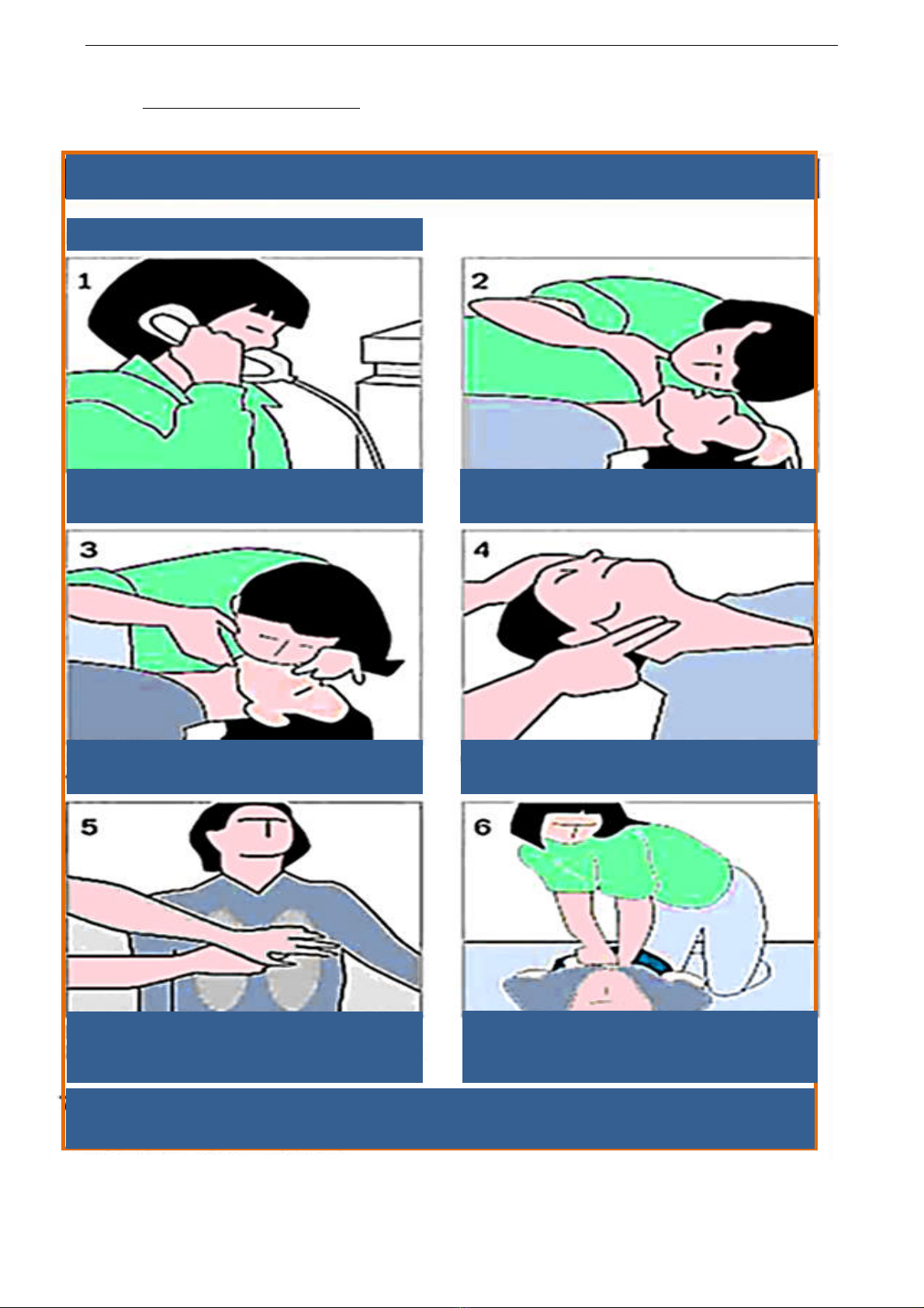
Basic CPR technique
Basic CPR (Cardiopulmonary resuscitation) technique
For adults
1: Call your local emergency
number
2: Tilt head, lift chin, check
breathing
3: Pinch nose shut and give
two breaths
4: Check pulse
5: If there is no pulse,
position hands in the
center of chest
6: Place one hand over other
and push down two inches
on the chest 15 times
7: If there is no pulse, continue with two breaths and 15 pumps for one
minute and recheck pulse – if no pulse – continue until arrives
SYNAPSE30 30W FM Exciter User Manual
Manual Revision Record
This record page is intended for recording revisions to your User & Service Manual for
SYNAPSE30-2G Exciter. Revisions can only be published by TEKO Broadcast Srl or its authorized
representatives. We recommend that only authorized or appointed personnel make changes, or
insert revised pages and ensure that obsolete pages are withdrawn and, either disposed of
immediately, or marked as superseded and placed in a superseded document file.
Rev.
No
Date
Entered
Reason
Signature
Entering Change
1
First Edition
2
07/2010
Change Display Front Panel
0110 fr
2.1
11/2010
Changed the back panel. Interlock on/off, Preemphasis an
Audio Impedance settable from the outside
0210fr
2.1.a
01/2011
Back panel. New graphics
0111fr
2.1.b
07/2011
Formatted text according to new rules
0211fr

SYNAPSE30 30W FM Exciter User Manual
Section Two
General Description
KEY FEATURES
Equipment is designed using the latest technologies and techniques available for Hardware
and Software and includes the following key features.
q High Performance At Low Cost
q Nominal RF Power 30w
q Very Low Signal Noise Typ. 80 Db
q High Stereo Performance Typ. 60 Db
q Extremely Low Distortion: THD, IMD & TIM Typ. 0,05%
q Completely Broadband
q High Spectral Purity > -100 dbc Spurious, > - 70 dbc Harmonics
q Easy to handle: self-explaining monitoring and setting of all important parameters
q Remote control for telemetry dB9 connectors available on rear panel
q Modular construction specifically designed to minimize spare parts set
q Built-in RF true wattmeter
q Output provided: RF, RF monitor
q AC mains 90-260VAC extend range
q ETSI - CCIR & FCC Compliant
q Very Compact Cabinet 1 Unit Rack 19”
q All functions controlled by a knob encoder and a two-row, sixteen character LCD display.
Intuitive parameters configuration
q Interlock, Reflected PWR, Forward PWR
OPTIONS
q RDS/RBDS Coder Programmable whit PC
q Stereo Coder
q FCC LPFM Code Station
q OIRT and JPN Version
SYNAPSE30 30W FM Exciter User Manual
TECHNICAL SPECIFICATIONS
GENERAL
Power Output
30W
RF Output Impedance
50Ω
RF Output Connector
“N” Type
Monitor RF
-54 dBc - BNC connector
Frequency Range
87.5 – 108 MHz
VSWR
1.5:1 Maximum
Frequency control
Synthesizer µprocessor controlled
Lock-in time
Typically 4 secs
Modulation mode
Mono, Stereo, Multiplex, AUX
Off-lock attenuation
> -80 dB
RF harmonics
Exceeds ETSI, EBU/CCIR/FCC requirements
RF spurious
Exceeds ETSI, EBU/CCIR/FCC requirements
Pre-emphasis
Flat/50/75 µs selectable from back panel
MONAURAL OPERATION
Audio frequency response
±0.15 dB 20 Hz to 15 kHz (+0/-2%)
Audio input Level
-3 to +9 dBm
Audio input impedance
600 ohm balanced, 10 KOhm unbalanced
Input Connector
XLR female ([6] fig. 2)
Audio frequency response
±0.1 dB, 30 Hz to 15 KHz
Total Harmonic distortion + noise
0.05% @ 400 Hz
Intermodulation Distortion
0.05%, 1 KHz/1.3 KHz, 1:1 ratio
Transient Intermodulation Distortion
0,05%, 2.96 KHz square wave and 14 KHz sine wave.
FM S/N Ratio
-82 dB RMS detector, -80 dB below ±75 KHz deviation, 50 µs
de-emphasis, weighted.
Distortion
0.05%, 2.96 KHz squere wave and 14 KHz sine wave
Pilot frequency
19 KHz ± 1 Hz
Phase Pilot
± 2° adjustable
Output Pilot
1 Vpp., BNC female
Audio filter Attenuation
≥-45 dB @ 19 KHz, > -40 dB 20 KHz to 100 KHz.
Modes
Stereo, Mono L+R, Mono L, Mono R.
MPX OPERATION (External coder)
Input Connector
BNC female ([5] fig. 2)
Composite input impedance
1,2 KOhm unbalanced
Composite input level
+6 to +12 dBm
Composite amplitude response
±0.2 dB 30 Hz to 100 kHz
THD+N on encoded channels
30 Hz to 15 kHz <0.05% @ 400 Hz
IMD
Measured with a 1 KHz and 1.3 KHz tones; 1:1ratio at FM 75 kHz
D2<-75 dB D3<-80 dB Typ. D2<-80dB D3< -85 dB
TIM (DIM30)
Measured with a 2.96 kHz square wave and a 14 kHz sine wave
FM S/N Ratio
-83 dB RMS detector, -80 dB below ±75 KHz dev.50 µs de-
emphasis, weighted.

SYNAPSE30 30W FM Exciter User Manual
STEREO OPERATION (Optional)
STEREO OPERATION
Audio frequency response
±0.25 dB da 30 Hz to 15 kHz
Audio input Level
-3 to +9 dBm
Audio input impedance
600 ohm balanced, 10 Kohm unbalanced
Input Connector
Two XLR female L & R ([9]-[10] fig. 2)
Stereo Separation
30÷80 Hz ≥-50 dB, 80Hz÷15 KHz ≥-60 dB (Typ. 65 dB).)
Total Harmonic distortion + noise
0.05% @ 400 Hz
Intermodulation Distortion
0.05%, 1 KHz/1.3 KHz, 1:1 ratio
Transient Intermodulation Distortion
0,05%, 2.96 KHz square wave and 14 KHz sine wave.
FM S/N Ratio
-75 dB RMS detector, -71 dB below ±75 KHz deviation, 50 µs
deephasis, weighted.
Stereo Separation
30÷80 Hz ≥-50 dB, 80Hz÷15 KHz ≥-60 dB (Typ. 65 dB).
Pilot frequency
19 KHz ± 1 Hz
Phase Pilot
± 2° adjustable
Output Pilot
1 Vpp., BNC female
Audio filter Attenuation
≥-45 dB @ 19 KHz, > -40 dB 20 KHz to 100 KHz.
Modes
Stereo
OPTIONS
AUXILIARY CONNECTIONS
ELECTRICAL
1. AC Input power
90 - 260 VAC ;50/60 HZ Single phase
2. AC Power consumption
70 VA @ 30W
3. Power Factor
Cos Φ> 0.92
4. Cooling
Forced air
ENVIRONMENTAL
1. Operating temperature
-10° C to + 50° C
2. Guaranteed performance
temperature
0° C to + 40° C
3. Max operating altitude
3,000 mt.
4. Relative humidity range
0 to 90%
PHYSICAL DIMENSION
1. Mounting
Standard 19” chassis 1 U Rack
2. Size
485 mm (W) x 405 mm (D) x 44 mm (H)
3. Weight
~ 4.0 Kg
OPTIONS
CODE
1. RDS/RBDS Coder Programmable with PC
SDZ00100
2. Stereo Coder
SDI03100
3. FCC LPFM Code Station
4. OIRT and JPN Version
SYNAPSE30 30W FM Exciter User Manual
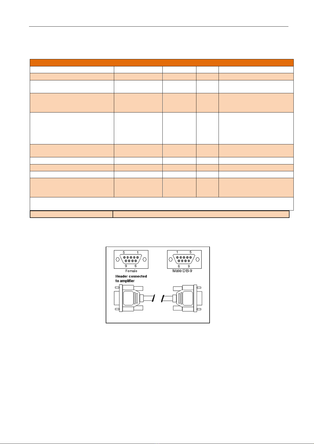
Input Connector
DB9 female ([7] fig. 2)
Pinout DB9 Connector
page was intentionally left blank
AUXILIARY TELEMETRY DB9 (REAR PANEL)
Pin
Description
Acronyms
Type
I/O
Value @ / Impedance
1
GROUND –
GND
Gnd
-
2
Current reading – reads
power Amp current
IPA
Analog
value
Æ
3.0V/3A
3
Voltage reading – reads
voltage supplied to power
Amp
VPA
Analog
value
Æ
3.0V/30V
4
Interlock Input – if not
continuously connected to
or open from ground
depending on selection:
N.O or N.C causes ‘Wait’
Interlock In
Control
(TC)
Å
Interlock CMD: L/H= Inhibit
5
Interlock Out
Interlock Out
Signal
(TS)
Æ
GND= Interlocked
6
TP
7
12V0
12 Volt
Power
Æ
8
GROUND –
GND
Gnd
-
9
Forward Output Power –
reads Forward RF Output
power
OUT-FWD-MEAS
Analog
value
Æ
3.0V/30W
Symbols:
Æ
Output
Å
Input

SYNAPSE30 2G 30W FM Exciter User Manual
MECHANICAL LAYOUT
1 2 3 4 5 6 7 8
1 Air Grid input inlet with whashable Air Filter
2 Allarm Leds Indicators
3 Direct Keys Command
4 Command Status Leds Indcators
5 Working Status Leds Indicators
6 Air Grid input inlet with whashable Air Filter
7 Browser keys
8 ESC key
FRONT PANNEL FUNCTION KEYS AND LEDS INDICATORS
SYNAPSE30 2G 30W FM Exciter User Manual
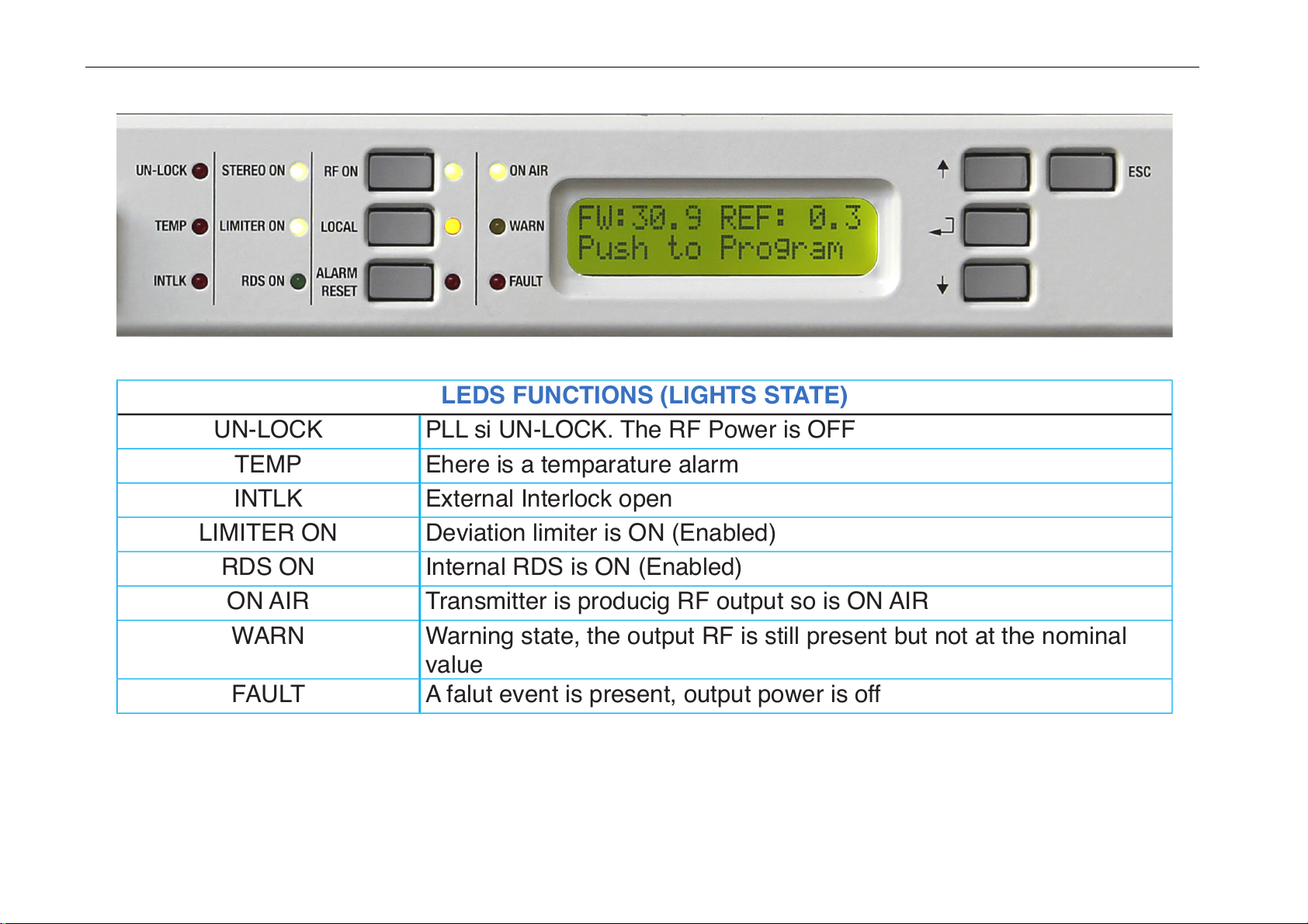
LEDS FUNCTIONS (LIGHTS STATE)
UN-LOCK PLL si UN-LOCK. The RF Power is OFF
TEMP Ehere is a temparature alarm
INTLK External Interlock open
LIMITER ON Deviation limiter is ON (Enabled)
RDS ON Internal RDS is ON (Enabled)
ON AIR Transmitter is producig RF output so is ON AIR
WARN Warning state, the output RF is still present but not at the nominal
value
FAULT A falut event is present, output power is off
SYNAPSE30 2G 30W FM Exciter User Manual
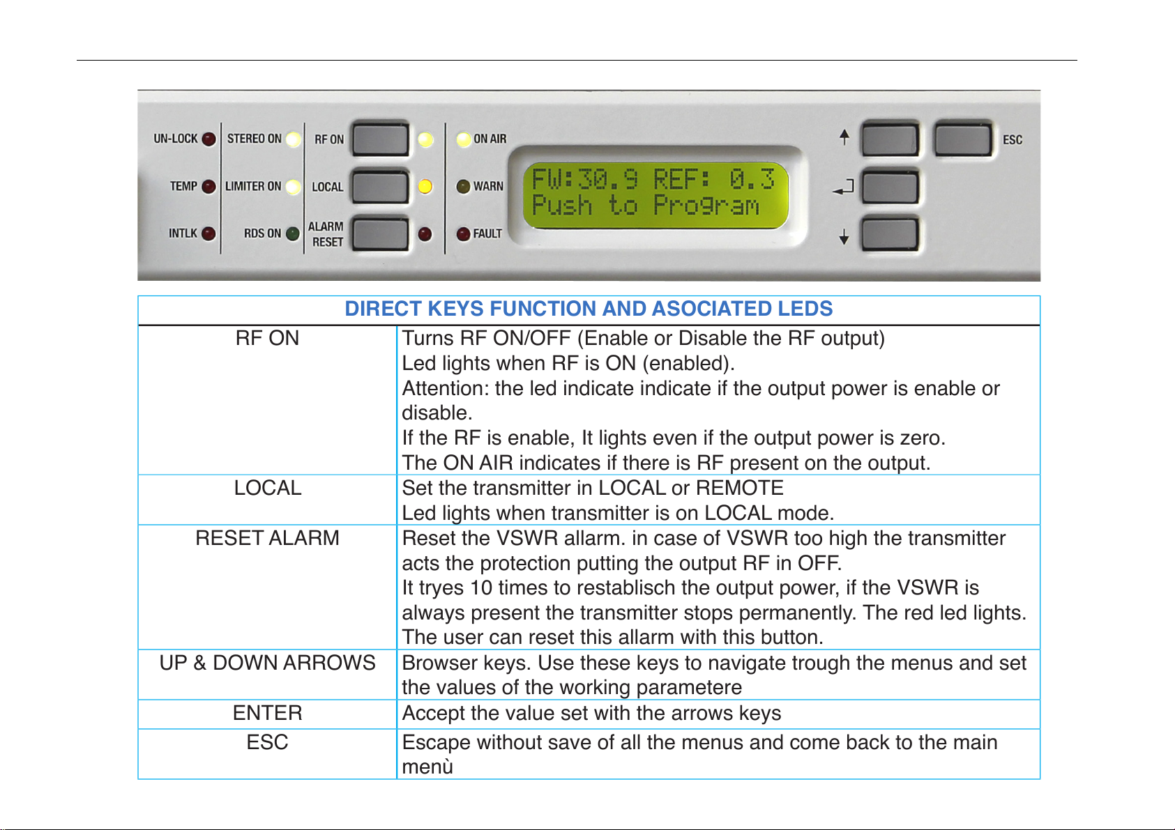
DIRECT KEYS FUNCTION AND ASOCIATED LEDS
RF ON Turns RF ON/OFF (Enable or Disable the RF output)
Led lights when RF is ON (enabled).
Attention: the led indicate indicate if the output power is enable or
disable.
If the RF is enable, It lights even if the output power is zero.
The ON AIR indicates if there is RF present on the output.
LOCAL Set the transmitter in LOCAL or REMOTE
Led lights when transmitter is on LOCAL mode.
RESET ALARM Reset the VSWR allarm. in case of VSWR too high the transmitter
acts the protection putting the output RF in OFF.
It tryes 10 times to restablisch the output power, if the VSWR is
always present the transmitter stops permanently. The red led lights.
The user can reset this allarm with this button.
UP & DOWN ARROWS Browser keys. Use these keys to navigate trough the menus and set
the values of the working parametere
ENTER Accept the value set with the arrows keys
ESC Escape without save of all the menus and come back to the main
menù
SYNAPSE30 2G 30W FM Exciter User Manual
1
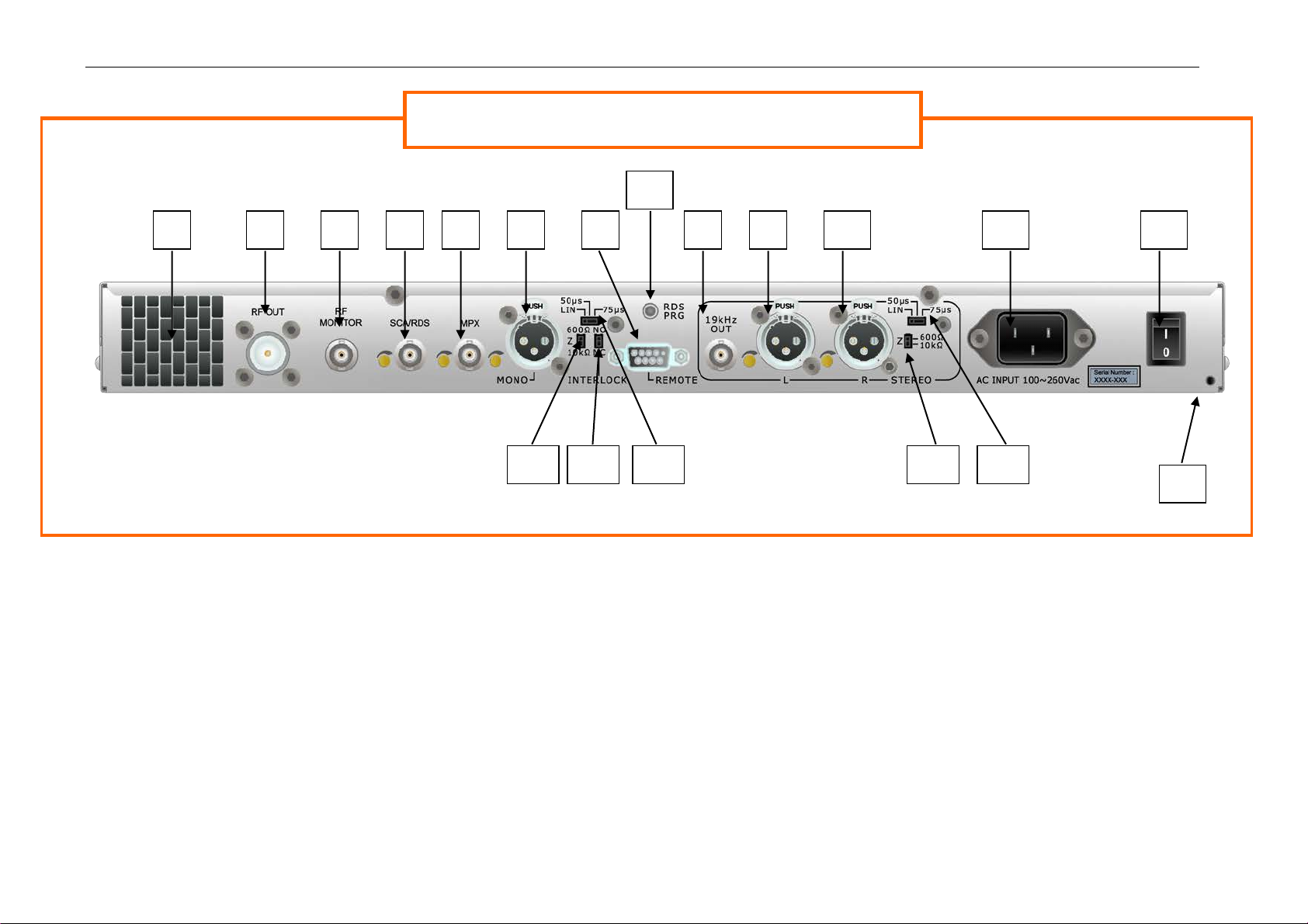
Fig.2
1 - Air Grid Input Outlet
2 - N Female Connector - RF Output
3 - BNC Female Connector – RF Monitor
4 - BNC Female Connector - AUX
5 - BNC Female Connector – MPX
6 - XLR Female Connector – Mono
7 - DB9 Connector - Remote control
8 - BNC Female Connector – 19 KHz Out
9 - XLR Female Connector – L Channel
10 - XLR Female Connector – R Channel
11 - VDE 3p 10A Mains Socket
12 - ON/OFF Switch
13 - Heart Connection
14 - Audio Mono impedance
15 - Interlock
16 - Mono Preemphasis
17 - Audio Stereo impedenze
18 - Stereo Preemphasis
19 - RDS Program (Optional)
SYNAPSE30 200 Rear View
5
6
3
11
7
13
12
SYNAPSE 30 Rear View
4
2
8
9
10
14
15
16
17
18
19
SYNAPSE30-2G 30W FM Exciter User Manual
Section Three
INSTALLATION & USE
DELIVERY
Please carefully check TEKO Broadcast delivery box for any punctures or other evidence
of damage. If any, please notify TEKO Broadcast as soon as possible.
When unit is delivered as STAND ALONE equipment the following items are included:
• Exciter
• Mains cable - in some countries cable is supplied with one connector only.
Customers must use matching connector to adapt to local standard mains socket
The above content could not be included in equipment delivered to Customers already
integrated in a system.
OPERATING RECOMMENDATIONS
To prevent failure please strictly follow
these IMPORTANT recommendations
Ensure that both front and rear part of equipment are properly ventilated. To prevent high
temperature inside equipment you must provide adequate ventilation to rack cabinet where
equipment is installed (temperature should not exceed 45 °C degrees)
PLEASE NOTE: Exciter cannot operate without top cover
The air-cooling system is designed to work in a closed box. Serious
OVERHEATING will occur if Exciter operates without top cover
SYNAPSE30 30W FM Exciter User manual
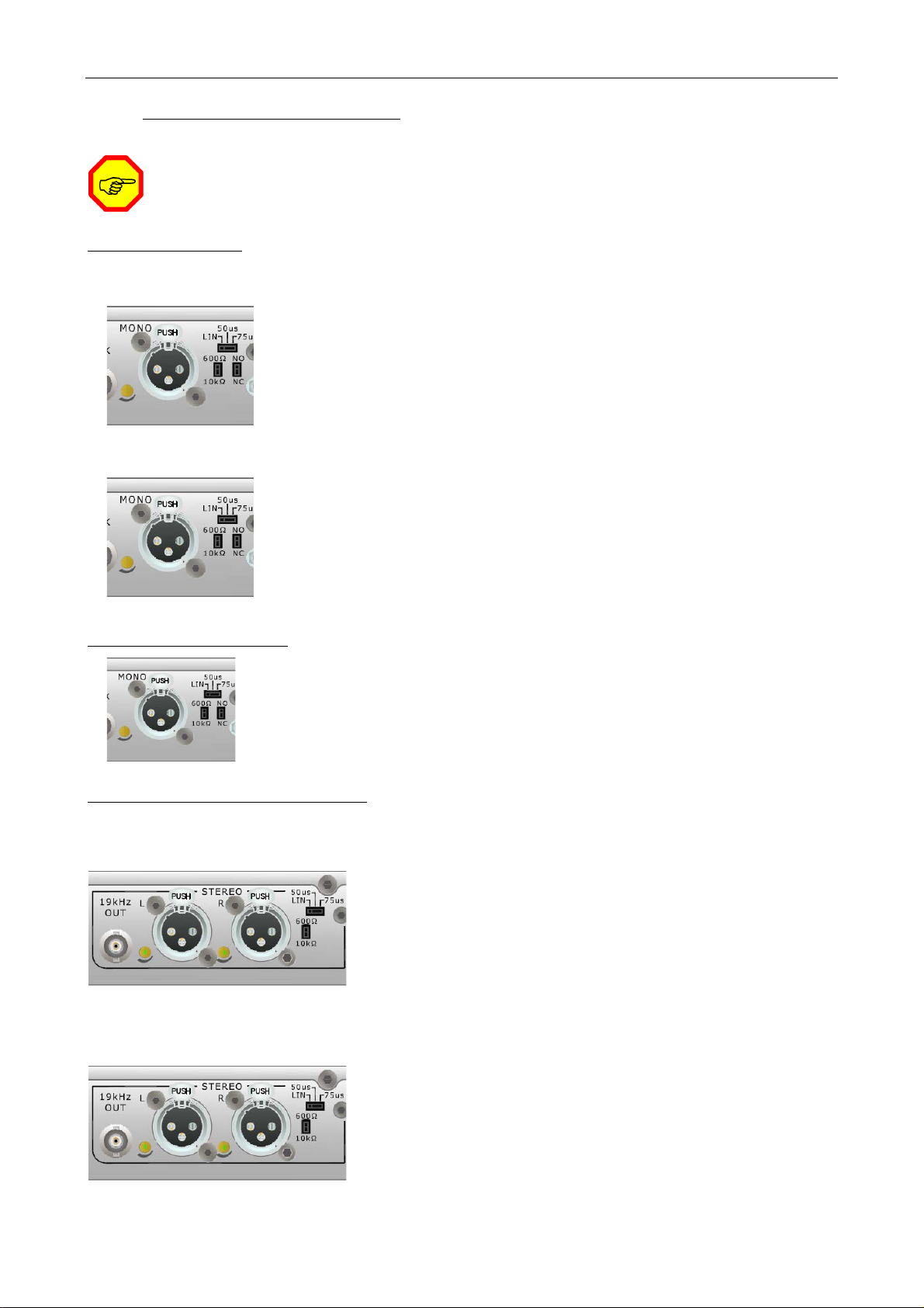
PRELIMINARY SETTINGS
All manual setting are on the rear panel
MONO CHANNEL
Input Impedance Setting and ADJ input Level
Set switch to on 600 or 10K to get the desired input impedance
Trimmer for ADJ AF Input
Preemphasis Mono Channel Setting
Set switch to on Lin-50uS or 75uS to get the desired Preemphasis
INTERLOCK SETTING
Set switch to N.O or N.C
Gli apparati di default vengono settati NO
STEREO CHANNEL OPTIONAL
Input Impedance
Set switch to on 600 or 10K to get the desired input
impedance
Trimmer for ADJ AF Input.Left & Right channel.
Preemphasis Stereo Channel Setting
Set switch to on Lin-50uS or 75uS to get the desired
Preemphasis
SYNAPSE30 30W FM Exciter User manual
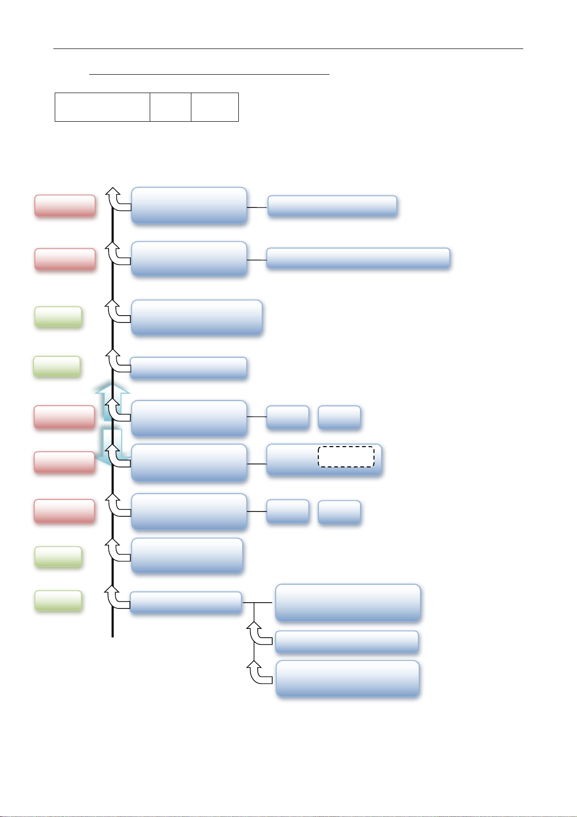
Mono$/$
Flow chart Arrows keys SYNAPSE 2G
Software
release
V.
xxx
date
Visual$
TEMPERATURE$$
Amb:$30°$C$
Visual$
AF$MEASURE$
(Mono)$
FREQUENCY$
87.5$to$108$MHz$
Push$to$Program$
Program$
Set Frequency from 87.5 to 108
MHz
FW:$XX$$$REF:XX$
Push$to$Program$
Program$
Set$Power$$0$to$p.MAX$
Visual$
IPA$MASURE$
ABOUT$
Model$$/$$Firmware$
SN: xxxx-xxx
Manufactured/distributor$
Visual$
COUNTRY$
www.name.xx$
RDS$CARRIER$SETTING$
Push$to$Program$
ON
OFF
Program$
LIMITER$
Push$to$Program$
$
ON
Program$
OFF
Stereo
Mono$
Push$to$Program$
$
Program$
Table of contents
Popular Transmitter manuals by other brands

Philips
Philips SBCHC552/05 Instructions for use

Interlogix
Interlogix UFT installation instructions

ARTEX AIRCRAFT SUPPLIES
ARTEX AIRCRAFT SUPPLIES B406-4 Operation, installation, and maintenance manual

Evacom
Evacom LX20 installation instructions

GAPOSA
GAPOSA Emitto Smart 16 manual

Vaisala
Vaisala DRYCAP DMT340 SERIES manual


