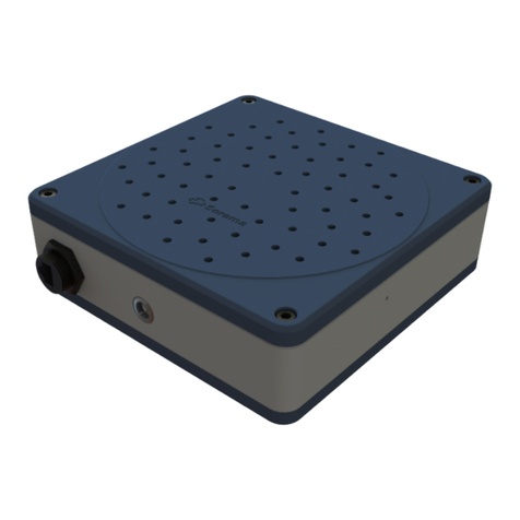
TEKSENS TUS Series User manual

Integrated Ultrasonic Level Meter
Operation Manual

1.
Overview
TUS Series Two-wire ultrasonic level meter is a kind of Intelligent non-contact level meter.
This product offers automatic power control, gain control, temperature compensation. Using
advanced detecting and computing technology to suppress jamming signal, so as to
improve measuring accuracy. This product can be widely used in measuring all kinds of
liquid level and solid material level.
2.
Parameters
Output
4—20mA (2-wire or 4-wire)
Power Supply
DC-24v(18v~30v)
Measurement Range
5m,10m,15m
Accuracy
0.2%(full scale)
Resolution
1mm
(
<10m
)
,1cm(>10m)
Blind Area
0.2—0.6m
Display Type
4-digits LCD
Display Mode
Liquid level, distance
Process Temperature
-25℃~70℃
Protection Class
IP66 or IP67
3.
Operating Instructions
LCD display signal
The main display interface:
After power on, level meter enters into the main display interface through starting procedure, liquid
level and distance are the two display modes for the main display interface. (The main display
interface is decided by the value set in P-04)
User Interface
PASS password entry
(enter 3456 to parameters setting)
P-00
ullage: the distance between probe
bottom and liquid level
P-01
full scale: 20mA current setting point
P-02
blind area: the minimum distance
between probe bottom and liquid level,
where level meter will workimproperly,
the general value between 30cm and
60cm
P-03
the change rate of measuring data: control the change rate of measuring data, display
the maximum variation of measuring data, Generally, the value is between 10mm to 30mm
for measuringliquid level.The levelmeter will convert to material level pattern when 00mm
is set

P-04
display content: display switch between distance and liquid level, display distance
when “00” is set, display liquid level when “01”is set, factory debug model when “02” “03” is set,
factory debug model is not recommended for field use
P-05
filter time: the parameter is valid only if P-03 is set (level meter is under material level).
The higher the parameter value, the stronger
the signal filtering ability, but at the same time, which can reduce the response speed of level
meter, so the value between 3 and 5 is recommended.
Buttons Define
Change display content: press this button to enter password interface under the condition of
the main display interface; press this button to switch to the next parameter interface under
the condition of user parameter interface.
Press this button to enter setting state when entering password or modifying parameter is
required. At this time, the modified digit will flash, press again, flashing digit will add“1”.
The modified digit will move to the next digit, use
and
together to modify
parameter or enter password.
Press this button after finishing modifying parameter, press again to return the main display
interface.
Parameter Setting (password: 3456)
Operation Steps
Under the main display interface, Press , password entry interface will appear after PASS
appears, at this time, use and together, enter password “3456”, press again,
P-00(ullage) interface will appear; Use and together to modify parameter value, press
after finish setting, press to switch to the next parameter interface If nextparameter
is required to modify. Press to return the main display interface after finish modifying all
parameter, then level meter enters measurement state. Most of the time, enter P-00 ullage and P-
01 full scale value, then the level meter can work well.

4.
Dimension ,
5.
Installation and Wiring
Installation
Easy installation by using thread and nut on sensor. Common installation methods are flange,
rack, riser
Flange Installation Rack Installation
Riser Installation
Riser can inhabit stirring or isolate foam at
surface (stirring and foam at surface has a certain influence onthe
use of level meter). The inner diameter of riser should be more
than 10cm. The length of riser equals to measured range. Cut a
45
ᵒ
incline
at
the
bottom
of
riser,
drill
a
8mm
hole
which
will
be
open
to atmosphere on the riser wall within the scope of the blind
area.
Range
A
B
C
5m(Liquid)
220mm
M58x2
74mm
10m(Liquid)
220mm
M66x2
74mm
15m(Liquid)
237mm
M70x2
85mm
20m(Liquid)
237mm
M70x2
85mm

90
0
Outdoor Installation
A mounting bracket is required for waterway and outdoor installation, as shownbelow:
Probe should be installed vertical to the surface of liquid level or material level, as shown
below:
If bracket sways in the wind, it will bring measurement error
Probe installation must be more than 35cm higher than the highest liquid (material) level
(40-60cm is required for anti-corrosion) to avoid entering the blind area of level meter. The
blind area will increase appropriately as the range increases.
Blind area(35-60cm)

100
There
should
be
no
obstacles
within
10ᵒemission
angle
of
ultrasonic
to
avoid
error
echo.
Avoid direct sunlight, and make sure the probe temperature is the same as environmental
temperature to achieve accurate measurement.
Installation in sealed vessel
Avoid air or pollutants from entering vessel, add sealant or Teflon tape at the thread of the
probe. Synthetic resin flange(like PVC)is recommended.
sealant or Teflon tape

rubber gasket
Probe should be installed vertical to the surface of liquid level or material level.
When there is vibration on vessel wall,rubber gasket can be used between the jar and level
meter to eliminate the influence of vibration.
Installation with a nozzle or riser installation,confirm diameter D
and nozzle length L, special debugging is required formanufacturer

Wrong Installation
Keep the highest liquid (material) Distractors below the sensor
level from the blind area
The probe should not be installed directly above the entrance of the
water/material.
Wiring

TEKSENS
YEDPA D212 AS Atasehir IST/TR
P: +90 216 660 12 77 -78
F: +90 216 660 12 79
www.teksens.com.tr
6.
Common problem
When LB appears in the left upper corner of the main display interface, that means the level meter
can’t receive echo signal, the data showed may be not the real value. If the value showed on the
level meter has no changes over the liquid level, and also LB hasn’t appeared in left upper corner
of the main display interface, which may be caused by too small blind area value, you can try to
increase blind area value.


