Telair ENERGY 2510D User guide

Vers. 004
G
B
INDICE
GENERATORS
ENERGY 2510D
USE AND MAINTENANCE MANUALAND
INSTRUCTIONS FOR INSTALLATION
GB
V
. 001
–
Februar
y
2011

G
B
1 FOREWORD ...…………………………………….…………………………………………..…………4
1.1 Purpose and scope of this manual .. ………….……………………………………………...4
1.2 Symbols and definitions …… …………………………………………………………….4
1.3 General information … … ………………………..………………………………………...4
2 GENERATING SET IDENTIFICATION DATA ……………….……………………………5
2.1 Components………………..……………………..………………………………………………...5
2.2 Identification plate…………………..………………………………………………………………5
2.3 Overall dimensions ………..……………….………………………………………………………5
2.4 Technical specifications….………………………………………….……………………………..6
3 SHIPPING, HANDLING, STORAGE …………………………. …………………………………….7
3.1 Storage …………………………………………………………………………………………..7
3.2 Weight . ……………………………………………………………………………………………7
3.3 Handling …………………….………………………………………………………………………7
4 INSTALLATION …………………………………………………………………………………….7
4.1 Preliminary information ……….………………………..……………………………………...7
4.2 Instructions for fastening the generating set .………………………………………………….7
4.2.1 Hanging assembly ………..….……………………………………………………………..8
4.2.2 Floor fastening…….………..............................................................................................8
4.3 Connecting the mufflers ............……………………………………………………………… 9
4.4 Connecting the fuel pipes …....……………………………………………………………….10
4.5 Connecting the fuel reserve…............…………………………………………………………..10
5 ELECTRIC CONNECTIONS ….....…………………………………………………………………..11
5.1 Preparing the Wiring connection ….........…………………...……………………………….11
5.2 230 VAC Wiring Connection …………….……………………………………………………..11
5.3 Connecting an External Network Relay ……….……………………………………………...12
5.4 12 Volt Battery connection ………………….……………………………………………….13
5.5 Electronic control panel connection….….…….…….…………………………………………..13
6 OPERATING INSTRUCTIONS …….………………………………………………………………..14
6.1 Fuel ………..……………………………………………………………………………………..14
6.2 Machine safety ………………………………………………………………………………….14
6.3 Information on not recommended uses.. …..…………….......………………………………...14
6.4 Useful tips ……….……………………………………………………………………………….14
7 USING THE GENERATING SET .....………………………………...………………………………. 15
7.1 Starting up the generating set ………………………………………..…………………………15
7.2 Turning the generating set off ….….…………………………..………………………………..15
7.3 Control and alarm functions……....….....…………….…………………………………………..15
7.3.1 Automatic Version (optional) .....…………………..………………………………………16
7.4 Manual Operation ……………..............………….……………………………………………16
7.4.1 Automatic Operation ............……...………….……………………………..............……..16
8 MAINTENANCE INSTRUCTIONS …….…..………………………………………………………...17
8.1 Service check list ……..….……………………………………………………………..………17
8.2 Maintenance not requiring skilled personnel ..……………………………..…………………..17
8.2.1 Checking the engine oil level .………....……………………….…………………………17
8.3 Maintenance operations to be carried out by skilled personnel . .......………………………..18
8.3.1 Engine oil replacement .…....…..…. …………….....……………………………………..18
8.3.2 Air filter maintenance ….……....………….....…………..……………….........………..19
8.3.3 Oil filter maintenance ………….................……..……………………………………..19
8.3.4 Checking the Alternator Belt .......…..…….....…………………………………………..21
8.3.5 Adjusting the Alternator Belt …………..…..……….........…………..………………………21
9 DECOMMISSIONING AND DISMANTLING INSTRUCTIONS ….………………..……….….… 22
10 RECOMMENDED FIRE-FIGHTING EQUIPMENT ……..………………………….……………….22
11 GENERAL WARRANTY TERMS …………………………………………………................…….22
12 ENERGY 2510 D WIRING DIAGRAM …………………………………………………......……….23
13 ENERGY 2510 D LIST OF SPARE PARTS …………………………………………......………...24
Energy 2510 D Vers. 001
2
Vers. 001 Energy 2510 D
G
B
3
Via E. Majorana , 49 48022 Lugo (RA) ITALY
"CE" COMPLIANCE STATEMENT
Under Machine Directive 89/392/EEC, attachment II A
We hereby represent that the generator-set, the data concerning which appear below, has been designed and
built to correspond to the essential safety and health requirements laid down by the European Directive on
Machine Safety.
This statement shall not be valid any longer if any changes are made on the machine without our written
approval.
Machine: GENERATOR-SET
Model: ENERGY 2510 D
Serial number: ………………………...
Directive of reference:
Machine Directive (89/392/EEC) in version 91/31/EEC
Low Voltage Directive (73/23/EEC)
Electro-magnetic Compatibility 2004/108/EC
Harmonised standards applied, especially: EN 292-1; EN 292-2; EN 60204-1
DATE........07/12/2010..........
THE PRESIDENT
G
B
1 FOREWORD
Refer carefully to this
manual before performing any operation on
the power generator set.
1.1 Purpose and scope of this manual
This manual has been drawn up by the
Manufacturer in order to provide basic
information and instructions for performing every
operation for servicing and using the generating
set in a proper and safe manner.
It is an integral part of the generating set
equipment, must be kept with care throughout the
life of the same, and must be protected against
any agent which could damage it.
It must follow the generating set if this is installed
on a new vehicle, or if its ownership changes
hands.
The information in this manual is addressed to
the personnel in charge of installing the
generating set, and to all those involved in its
maintenance and use.
This manual sets out the purpose the machine
was designed for, and contains all the information
required to guarantee that it is used in a safe and
proper manner.
Constant compliance with the instructions laid
down here will guarantee the safety of the user,
operating economy and longer life of the
machine.
To facilitate reference, this manual has been
subdivided into sections specifying the main
notions contained therein; for quick consultation,
refer to the table of contents.
The most important parts of the text are in bold
letters and preceded by symbols described here
below.
Please read the contents of this manual and of
the reference documents carefully. This is the
only way to ensure that the air conditioner will
work smoothly and reliably over time, while
protecting people and property from damages.
Note: The information contained in this
publication was correct at the time it went to print,
but may be modified without advance notice.
1.2 Symbols and Definitions
"Graphic safety symbols” have been employed in
this booklet to identify different levels of danger or
important information.
This means that you must
pay attention to avoid serious consequences
which might lead to serious accidents or damage
the health of the operators.
This means a potentially
hazardous situation which could lead to accidents
or damage to property.
This calls the user’s
attention to a potentially dangerous situation
which could cause malfunction to or damage the
machine.
The drawings are only provided by way of
example.
Even though the machine you actually have may
differ from the illustrations contained in this
manual, safety and information about the same
are guaranteed.
The manufacturer, as part of his policy of
constant product development and updating, may
introduce changes without giving any notice.
1.3 General Information
The ENERGY generating set has been designed
for installation on vehicles. It can deliver power at
a voltage of 230 VAC 50 Hz.
The ENERGY 2510D model must be fed with
Diesel oil.
In order to achieve a low noise level, the
ENERGY 2510D generating set is provided with
an internally insulated sound-proofing case.
It can be accessed easily in order to perform
maintenance work, and is provided with a remote
control panel which can be installed inside the
vehicle.
The generating set can be connected to the tank
of the vehicle as long as the fuel type is
compatible. Otherwise, it is possible to install a
special tank which can be supplied as an option.
Energy 2510 D Vers. 001
4

G
B
2 GENERATING SET IDENTIFICATION
DATA
12 Bar code
2.1 Components (Fig. 1)
1 Sound-proofing casing
2 Supporting brackets
3 Access door closure
4 Access door
5 Electronic control panel
6 Vibration mount
7 Anchoring bracket
8 Technical specifications sticker
2.3 Overall dimensions
Figure 3 shows the overall dimensions of the
Energy 2510D generating sets.
2.2 Identification plate (Fig. 2)
1 Generating set model A B C D E
mm 295 415 660 710 377
2 Model code number
3 Serial number
4 Year of manufacture
5 Power factor
6 Frequency
7 Maximum electric power
8 Maximum current
9 Rated voltage 230V AC
10 Current delivered at 12V DC
11 Weight
Vers. 001 Energy 2510 D 5
G
B
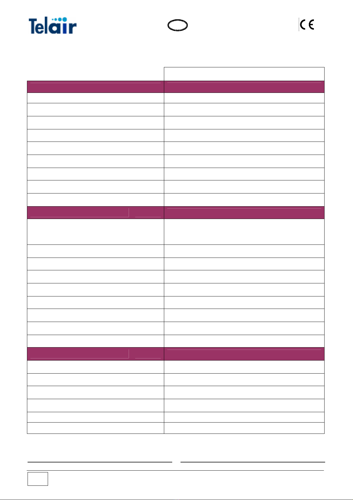
2.4 Technical specifications
ENERGY
ENGINE 2510 D
Type Diesel single cylinder air cooling
Engine Hatz 1B20V
Displacement cm3 232
Bore x Stroke mm 69 x 62
Consumption gkW / h 260
Fuel supply Diesel fuel
Oil sump capacity litres 0,950
Speed governor Masse centrifughe
ALTERNATOR 2510 D
Type Synchronous, single phase, self-adjusting, two poles,
brushless
Max power kW 2,2
Continuous power kW 2
Voltage/ Frequency V / Hz 230 / 50
Continuous current output A / Vdc 2,5 / 12
Rotor insulation class H
Stator insulation class F
Cooling Centrifugal fan
GENERATOR 2510 D
Overall weight kg 90
Dimensions (L x W x H) mm 660 x 415 x 377
Starting Electrical
Fuel supply Electrical
Noise level 85 LWA(65 dBA7 m)
Operation Hours h 7
Energy 2510 D Vers. 001
6
G
B
3 SHIPPING, HANDLING, STORAGE
3.1 Storage
The generating set is protected during transport
by suitable carton packaging and a wooden
base. It must be stored horizontally, in a covered,
dry and ventilated area.
Do not turn the package
upside down. The correct position is the one
shown by the symbol printed on the package
( )
3.2 Weight
Total weight including packing:
ENERGY 2510D 90 kg
3.3 Handling
The generating sets, complete with their
packaging, can be handled using common lifting
and transport equipment.
The boxes are provided with spacers in order to
allow for the introduction of transpallet forks.
During lifting and
transport, comply with accident prevention
and safety regulations. Use lifting and
transport equipment with a capacity greater
than the load to be lifted.
4 INSTALLATION
4.1 Preliminary information
Before installing the
generating set, it is absolutely necessary to
read these instructions to prevent any
installation errors.
The generator must be
installed so as to prevent water seeping
directly into the alternator through the air
inlets; it must therefore be protected.
Incorrect installation of generating sets can
cause irreparable damage to the equipment
and endanger the safety of users.
Should the generating sets be installed not in
compliance with the instructions in this manual,
the Manufacturer shall not be held responsible
for malfunctioning or for the safety of the
generating set, by the terms of the Italian Law
Decree D.M. 89/392/EEC. The Manufacturer
shall also not be liable for any injury or damage
to people or property.
Installation must be
performed by skilled and adequately trained
personnel only.
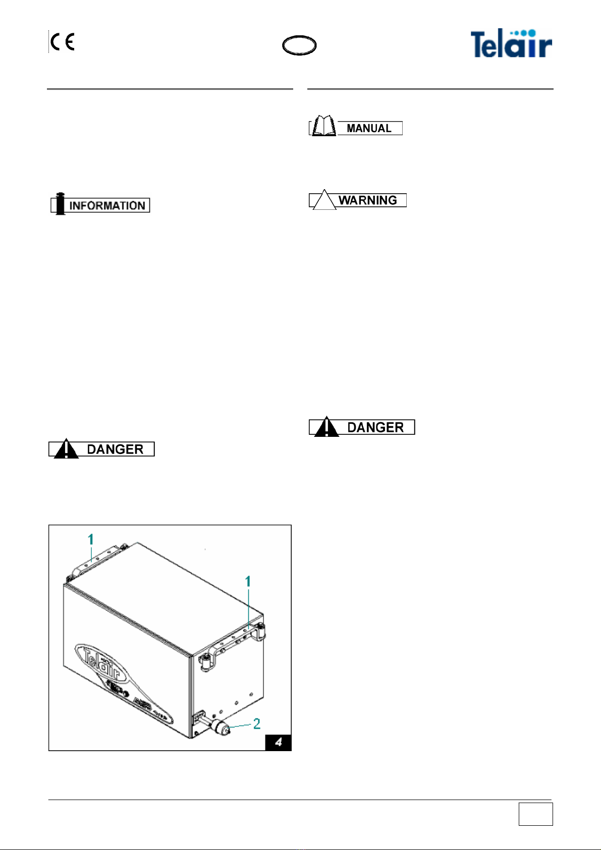
4.2 Instructions for fastening the generating
set
The ENERGY 2510D generating sets are
provided with anchoring brackets with extra
vibration dampers (fig. 4, ref. 1) and a fuel filter
(fig. 4 ref. 2) to be fitted along the generator
feeding pipe. The brackets allow for hanging
assembly. The brackets allow for hanging and
floor assembly. This kind of assembly provides
the following advantages: less room taken up,
quick installation, easy access for routine and
unscheduled maintenance.
Make sure that there is enough room around the
hood of the generating set to let cooling air
through; also leave 10 cm free room between the
hood and the surrounding parts.
Should the generating set air intake be behind a
wheel of the vehicle, care should be taken to
prevent water from being sprayed into the
generating set by the wheel when raining.
Vers. 001 Energy 2510 D 7
G
B
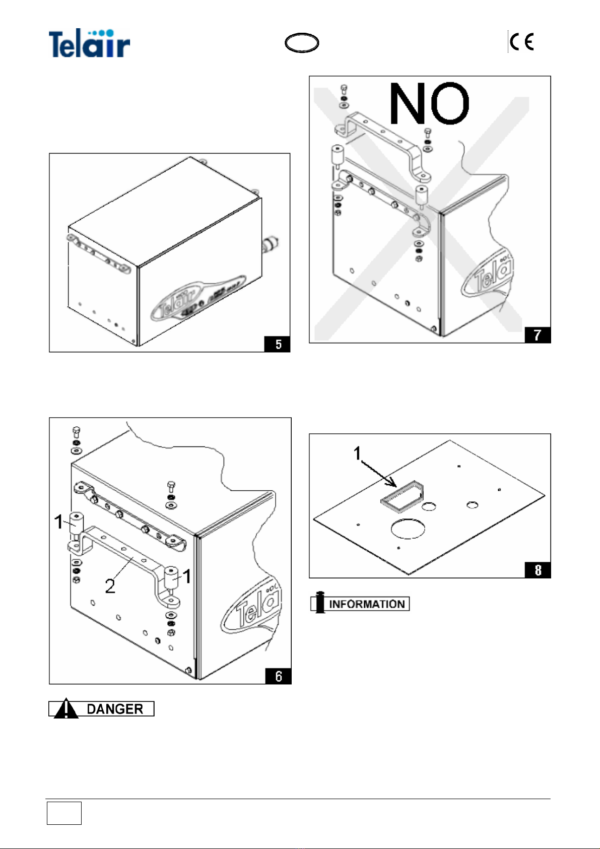
4.2.1 Hanging assembly
The generator, when sticking out of the package,
is preset for hanging assembly, as shown in fig.
5.
The package also contains 4 vibration-damping
cylinders (fig. 6 ref.1) and 2 brackets for hanging
assembly (fig. 6 ref. 2).
The vibration-damping
cylinders must imperatively be fitted as
shown in fig. 6. They must be pressed, and
NOT extended (as shown in fig. 7) by the
generator weight.
4.2.2 Floor fastening
The package contains a drilling jig, which allows
the generator bearing surface to be prepared
quickly, fig. 8.
Place a spongy, heat-
resistant gasket around the outlet opening of
the exhaust pipe. The gasket height must
reach the bottom of the generator and has the
purpose of preventing hot air from spreading
inside the generator compartment.
The brackets of the generator must be moved in
order to fasten the Energy 2510D on the bearing
surface.
On both sides, remove the hole plugs (fig. 9 ref.
1) and screw out the screws (fig. 9 ref. 2) in order
to remove the bracket (fig. 9 ref. 3).
Energy 2510 D Vers. 001
8

G
B
Place the bracket (fig. 10 ref. 3) on the 4 holes
which were previously covered by the plugs
using the same screws (fig. 10 ref. 2) and apply
the hole plugs (fig. 10 ref. 1) in the seats which
previously housed the screws.
The generator can now be located on the
previously drilled surface (fig. 8) using the
suitable vibration-damping cylinders (fig. 11 ref.
1)
4.3 Connecting the mufflers
The Energy 2510 D generating set comes with a
suitable exhaust pipe kit which consists of 2
mufflers, 2 exhaust pipes and their connections
Insert first the U-shaped fastening clamp code
00828 on a terminal of the 2m pipe code 00705,
let the pipe terminal through the suitable slot by a
section of at least 3 cm (fig. 12 ref. 3) into the
exhaust manifold of the generator (fig. 12 ref. 1),
then tighten the U-shaped clamp (fig. 12 ref. 2)
on the pipe-manifold connection.
Connect the 2-terminal muffler code 01760 (fig.
13 ref. 3) on the other end of the 2m pipe (fig. 13
ref. 1) observing the arrow showing the gas flow.
Tighten with a clamp D.32-35 code 01655 (fig. 13
ref. 2). Place the muffler (fig. 13 ref. 3) under the
floor of the vehicle via a suspending rubber
stopper code 02440 (fig. 13 ref. 4) and fasten the
Vers. 001 Energy 2510 D 9

G
B
2 mt pipe in several spots (fig. 13 ref. 1), taking
care that such fastening does not prevent the
generator from being drawn out for maintenance
purpose.
Now insert the 40 cm pipe code 03161 (fig. 13
ref. 6) in the other end of the muffler (fig. 13 ref.
3) and tighten by means of a clamp D.32-35 code
01655 (fig. 13 ref. 5).
Then insert the other end of the 40 cm pipe (fig.
14 ref. 6) in the 1-terminal muffler (fig. 14 ref. 8)
and tighten by means of a clamp D.32-35 code
01655 (fig. 14 ref. 7).
Place the muffler (fig. 13 ref. 3) under the floor of
the vehicle via 2 suspending rubber stoppers
code 02440 (fig. 14 ref. 9 & 10)
4.4 Connecting the fuel pipes
No. 2 pipes come out of the generator. The pipe
with a larger inside diameter (7mm), on which the
fuel oil filter is located, is the fuel inlet one. The
pipe with a smaller inside diameter (5mm) is the
fuel return one.
If an independent tank is fitted, the installation
position must be chosen so as ensure that the
fuel pipe length is reduced to a minimum. Also
ensure that the hose cross-section is not reduced
due to choking, bending or crushing.
We advise to install the tank at the same height
as the generating set. If it is fitted in a lower
position, the installation height difference should
never exceed 20 cm.
Do not install the fuel tank next to sources of
heat; the tank should be protected from the risk
of outside water seeping.
Carry out the fuel tank-to-generating set
connection by using rubber hoses suitable for
Diesel oil, with an ID of 7 mm (code 00536) for
the fuel delivery pipe and an ID of 5 mm (code
01548) for the return pipe.
Both fuel pick-up and
return must take place in the tank and NOT
through branch pipes.
Should the fuel flow rate to the generator be
insufficient owing to a long route covered by the
feeding pipe, it is advisable to install an additional
fuel pump code 00507. This pump, which is
equal to the one fitted inside the generating set,
is electrically operated. The electric control which
drives the additional pump is located in a 3-pin
connector (fig. 15 ref. 1) in the generating set
near the 12 Vdc terminals.
4.5 Connecting the Fuel Reserve
If the tank is provided with a fuel reserve
indicator. To electrically connect this component,
the reserve wire on the fuel tank must be
connected, via an electric lead, to the 3-pin
connector terminal (fig. 15 ref. 2) inside the
generating set, close to the 12 Vdc terminals. If
the tank reserve indicator has 2 leads, connect
the other lead to the ground.
Energy 2510 D Vers. 001
10
G
B
A special fuel warning light located on the control
panel (fig. 24. ref. 8) will light up to show that the
fuel level inside the tank has gone below the safe
reserve level.
5 Electric connections
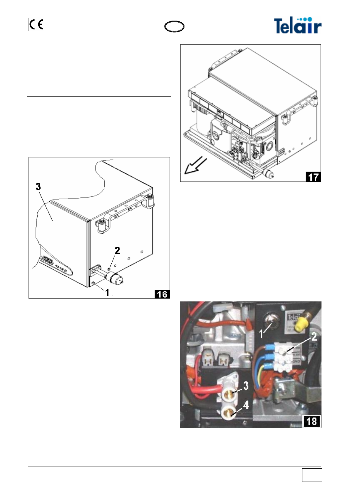
5.1 Preparing the Wiring connection
By using the special key to open the lock,
remove the front door (fig. 16 ref. 3).
Then remove the bottom surface locking screw
(fig. 16 ref. 1) on both sides.
Take out the bottom surface with the engine all
the way to the mechanical stop (fig. 17).
If you wish to completely remove the engine
surface, screw out the setscrews (fig. 16 ref. 2)
too.
5.2 230 VAC wiring connection
To connect loads to the power generating set,
use a three-pole cable up to the applicable
standards in force. The correct cross section is
shown in Table 1.
For connection to the 230V input line, the
generating set is equipped with a special terminal
strip (fig. 18 ref. 2) to which the cables must be
connected.
Even if the generating set is provided with a
thermoswitch to disconnect power supply (fig. 18
ref. 1) in case of overload or short-circuit, a
suitably calibrated circuit breaker should be
installed inside the switchboard of the vehicle,
which disconnects the power line to users
whenever power input exceeds 15 Amp. for the
Energy 2510D
If the thermoswith of the generating set has been
operated, press the button (fig. 18 ref. 1) to
restore closed circuit and power delivery
conditions.
Vers. 001 Energy 2510 D 11
G
B
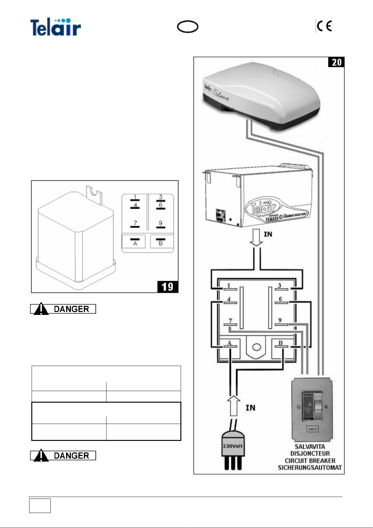
5.3 Connecting an External Network Relay
An (optional) relay or change-over switch code
05423) (fig. 19) should be fitted to the vehicle
wiring system. Its purpose is to insulate the
generating set when it is connected to an
external electric input network.
Connect the relay according to the following
instructions:
•Connect the two wires of the 230 V line of the
generating set to the PINS 1 - 3.
•Connect the user line to the PINS 7 - 9.
•Connect the external line to the PINS 6 – 4.
•Jumper the PINS 4 – A.
•umper the PINS 6 – B.J
Check the proper
position of the 230 V current pick-up line
carefully. A wrong connection could cause
irreparable damage to the generating set or
reate dangerous short circuits.c
Table 1
LINE CONNECTION 230 Vac
Length < 6 m Length > 6 m
Cross Section 2.5 mm2Cross Section 4 mm2
BATTERY CONNECTION
Length < 6 m Length > 6 m
Cross Section 25 mm2Cross Section 36 mm2
Electric connections to
the generating set should be carried out by
killed personnel only.
s
Energy 2510 D Vers. 001
12

G
B
5.4 Battery Connection
e 1) in
he
le of the
surface, and
attery must have a capacity of at
ast 80 A/h.
To start up the generating set, you must connect
to the vehicle battery using a sheathed cable (to
determine its cross-section, see Tabl
compliance with the regulations in force.
For this purpose, the generating set is provided
with two terminals (fig. 18) used to connect t
positive and the negative poles of the battery.
Connect the positive pole cable (red cable) to the
terminal which is already provided with a red
cable (fig. 18 ref. 3) and the cable of the negative
pole (black cable) to the terminal already
provided with a black cable (fig. 18 ref. 4). The
cable of the negative pole must be of the same
cross-section as the positive cable and must be
connected to both the negative po
battery and the chassis of the vehicle.
The contact must be good. If necessary, remove
any paint or rust from the contact
protect the connection with grease.
The start-up b
le
Always fit a 100 A fuse
onto the cable connecting the generating set
the positive pole of the battery.
.5 Electronic Control Panel Connection
nd make a rectangular hole sized 30 x 32 mm.
to
5
Choose the position you want inside the vehicle
a
2) from the control panel to the generating
e remind you that a 5 m long cable is delivered
3797), 10 m (code
3798), 15 m (code 03799).
Identify the path for laying the connection cable
(fig. 2
set.
W
standard. Optional cables in longer sizes are
also available: 7 m (code 0
0
nnector side
ame
ntil you hear the click of the fastening tabs.
Arrange the connection cable (fig. 22) so as to
connect the black connector side (fig. 22 ref. 1) to
the control panel, and the white co
(fig. 22 ref. 2) to the generating set.
Let the connection cable coming from the
generating set out of the hole and connect the
black connector of the cable (fig. 22 ref. 1) on the
back of the electronic control panel. Fasten the
electronic control panel (Fig. 21) using self-
tapping screws sized 3 x 20 mm, and make sure
that the rear part does not touch other surfaces;
use slight pressure to fasten the plastic fr
u
(fig.
ator control box; observe proper connection
ide.
Connect the other end of the connection cable
(fig. 22 ref. 2) to the proper white connector
23 ref. 1) which is located on the side of the
gener
s
Vers. 001 Energy 2510 D 13
G
B
6 OPERATING INSTRUCTIONS
ENERGY series generating sets consist of Diesel
endothermic engines connected to an alternator
able to produce both alternating and direct
electrical current. The generating sets are
assembled inside a steel plate casing, insulated
and sound-proofed using special sound-
hich is fitted standard on the generating set.
.1 Fuel
s as provided for by the following
BS-2869-A1/A2 or ASTM-D-975-
oil to the fuel according to the
llowing table.
deadening material.
Fuel is fed to the endothermic engine via a pump
w
6
Use Diesel oil in compliance with the minimum
requirement
standards:
EN-590 or
1D/2D.
If outdoor temperature is below 0°C use winter
Diesel oil or add
fo
Ambient
temperature
R
tage
ecommended oil
percen with
upon start-up summer winter
°C fuel fuel
0 to -10 20% ----
-10 to -15 30% ----
-15 to -20 50% 20%
-20 to -30 ---- 50%
6.2 Machine safety
The generating sets come with perfectly sealed
casings, so there is no danger of contact with any
moving or high temperature parts or with live
the reach of children or
ndards as listed in
e statement of compliance.
cables.
The doors open with a lock and key. The keys
must not be left within
inexperienced persons.
The generating sets have been manufactured in
compliance with the safety sta
th
The generating sets
must only and exclusively be used with their
oors shut.
olvents, etc.) from
ear the generating sets.
not in contact with any
up the fuel tank while the engine is
ets or the wiring
hes with others having higher
e engine turned off
nd by skilled personnel.
d
Remove any flammable substance (for
example: petrol, paints, s
n
Make sure that any hot parts of the
generating sets are
flammable material.
Never fill
running.
Never touch the generating s
connections with wet hands.
Never replace the fuses or the
thermoswitc
amperage.
Should any electrical part need checking, this
must only be done with th
a
The generating set is
provided with an internal combustion engine,
t your hands or
ny objects inside the hood.
.3 Information on not recommended uses
the fuel used is therefore highly flammable.
The exhaust gases are conveyed under the
hood; their temperature, inevitably, is quite
high, even though they are mixed with
cooling air. Do not touch the hood areas near
the exhaust, and do not pu
a
6
This generating set must
be installed and used by skilled and
authorised personnel only, according to the
manufacturer’s instructions. This generating
set must only and exclusively be used to
produce electrical power on vehicles
provided with an electrical system built to
standards and according to the quantity of
ower delivered.
.4 Useful tips
e
ted load, at least for the first 50 running hours.
USING THE GENERATING SET
p
6
To make the best use of the generating sets,
remember that even minor overloads - if they last
long enough - will cause the contact of th
thermoswitch to open (fig. 13 ref. 1)
During the running-in period, do not subject the
new engine to a load higher than 70% of the
ra
7
Energy 2510 D Vers. 001
14
G
B
The generating sets are provided with an
electronic remote control panel which allows you
to perform starting up / turning off operations as
well as to check their running conditions.
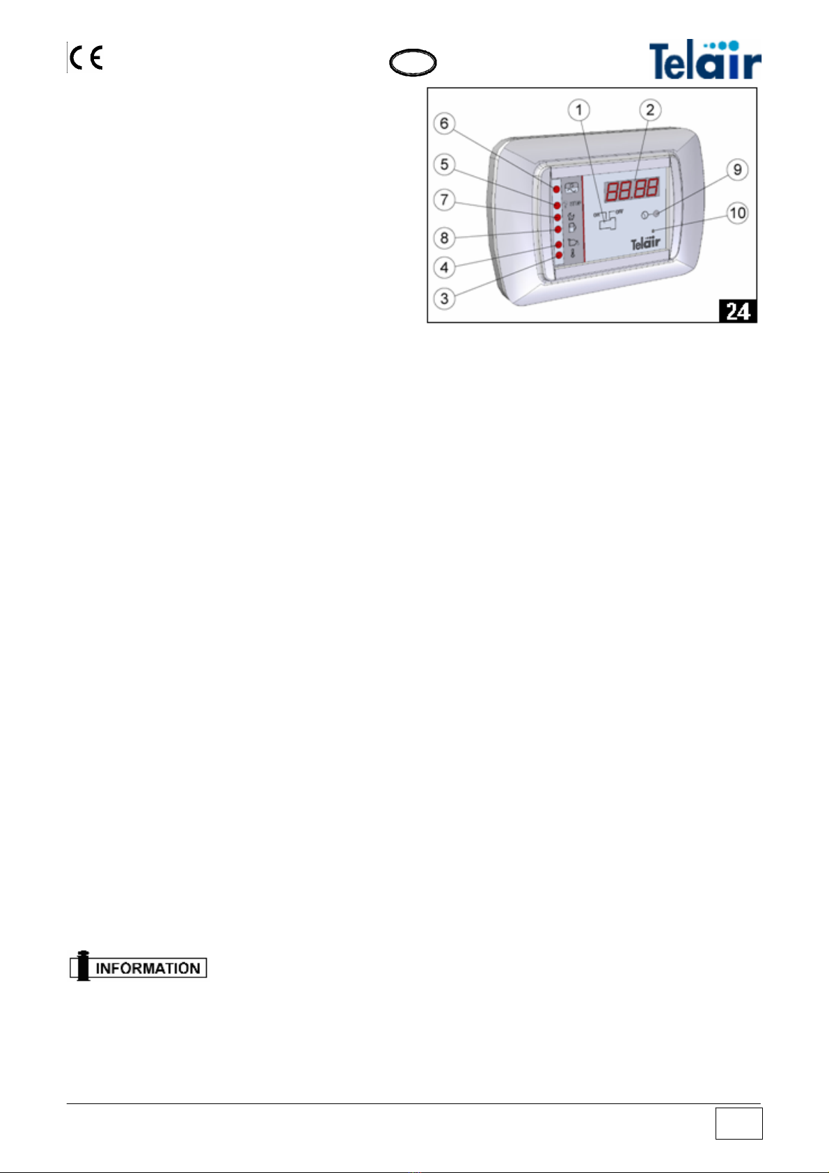
The elements making it up are (fig. 24):
1 ON/OFF switch
2 Display unit
3 High temperature indicator
4 Minimum engine oil level indicator
5 Engine start-up failed indicator
6 Generator running indicator
7 Engine oil change indicator
8 Fuel reserve indicator
9 Display changeover switch
10 Reset
7.1 Starting up the generating set
Before the first start-up check the oil level.
Set the start-up switch (fig. 24 ref. 1) to “ON”
position. The word “WAIT” will appear on the
display for 8 seconds. When these have run out,
the electronic control panel will start the first
automatic procedure for starting up the
generating set. If the engine starts up at the end
of this phase, then the “generator running”
indicator (fig. 24 ref. 6) will start to flash.
Should the engine not start up, this automatic
procedure will be repeated up to 4 times. If the
engine has not started up yet at the end of this
complete cycle, the “start-up failed” indicator ( fig.
24 ref. 5) will light up to signify that the
generating set has failed to start up.
If only the “start-up failed” indicator (fig. 12 ref. 5)
stays lit, you can repeat the start-up procedure
several times.
If the generating set has not started up at all
even after many attempts, you will have to get in
touch with the After-sales service.
7.2 Turning the generating set off
To stop the generating set, set the "ON/OFF”
switch to "OFF" position (fig. 24 ref. 1).
Always turn the
generating set off after disconnecting the load
7.3 Control and alarm functions (Fig. 24)
2 Display unit: when the generating set has
started up, the total running hours will be
displayed. Press the button (fig. 12 ref. 9) to
display the partial running hours of the
generating set since the latest engine oil change.
3 High temperature indicator: this pilot lamp
will light up when the temperature of the
generating set goes over its safety value; the
engine will stop at the same time.
4 Minimum engine oil level indicator: this pilot
lamp will light up to indicate that the oil in the
engine has gone below the minimum level.
5 Engine start-up failed indicator: this pilot
lamp will light up to indicate that the generating
set has not started up, after all four attempts at
starting up have failed.
7 Engine oil change indicator: this pilot lamp
will light up when the engine has reached 100
running hours since the latest oil change. Upon
every engine oil change the After-sales service
staff must reset the Timer to make it restart from
zero.
8 Fuel reserve indicator: this pilot lamp will light
up when the fuel level has gone below its reserve
level (about 4 litres) inside the extra tank.
9 Display changeover switch: press this button
to display the running hours elapsed after the last
change of the engine oil.
10 Reset: when the display shows any
characters without logic, the panel is to be
reinitialised. Press the Reset key and, holding it
down, switch on the panel. When 4 zeroes
(0000) are shown on the display, the panel is
reinitialised.
Vers. 001 Energy 2510 D 15

G
B
7.3.1 Automatic Version (optional)
If you wish the start-up batteries to be recharged
automatically in the En 2510D generating sets, it
is possible to install the ASP (optional) automatic
control panel (fig. 25) instead of the manual
control panel.
The elements making it up are:
1 ON/OFF switch for the start-up and switch-off
function
2 Display
3 High temperature indicator
4 Minimum oil level indicator
5 Start-up failed indicator
6 Generator running indicator (flashing)
7 Maintenance request indicator
8 Fuel reserve indicator
9 Hour or voltmetric changeover switch button
10 Reset
11 Battery charged indicator
12 Automatic function indicator
13 AUTO/MAN switch for the automatic or
manual function
7.4 MANUAL operation
See section 7.3
7.4.1 AUTOMATIC operation
Turn the AUTO/MAN switch (fig. 25 ref. 13) to the
AUTO position and set the start-up switch (fig. 25
ref. 1) to ON position.
The automatic function indicator (fig. 25 ref. 12)
will light up. If the battery which supplies the
generating set has a voltage of more than 11.5
Volts, the battery charged indicator (fig. 27 ref.
11) will light up.
When the voltage at the ends of the 12V DC
terminals of the generating set is lower than 11.5
Volts, the battery charged light indicator (fig. 27
ref. 11) will go off and the generating set will
begin the start-up procedure (similar to that of the
manual operation).
During the operation in automatic mode, the
display (fig. 25 rif. 2) will show the total running
hours of the generating set. Press the hour or
voltmetric changeover switch button (fig. 25 ref.
9) to display the voltage at the ends of the 12V
DC terminals, i.e. at the ends of the battery.
When the battery is charged, and anyway after at
least 15 minutes’ running, the battery charged
hours indicator (page 25 ref. 11) will light up and
the electronic control panel will turn off the
generating set.
Setting the switch to the
automatic position after turning the control
panel on sets the generating set in stand-by
mode and does NOT activate the automatic
function.
Remember that the time which is taken by
the generating set in automatic mode to
recharge the battery may vary according to
the battery status, the amount of connected
batteries and the season temperature.
Generally, the lower the temperature the less
the time required to charge the battery.
Applying any load higher
than the energy just then available in the
battery will prevent the generating set from
turning on due to insufficient voltage.
8 MAINTENANCE INSTRUCTIONS
Only use original spare
parts. Using poorer quality spare parts may
damage your generating set.
Routine checks and adjustments are of the
essence in preserving a high level of
performance. Routine maintenance also
ensures long generating set life.
Energy 2510 D Vers. 001
16
G
B
8.1 Service check list
Before performing any
check or maintenance operation on the
generating set, turn the ON/OFF switch of the
control panel to the OFF position and the
AUTO/MAN switch of the control panel to the
MAN position.
Then disconnect the red 12 Vdc cable from
the terminal (Fig. 10 Ref. 1)
This way you can operate under safe
conditions as the generating set cannot start
up.
If you do not use the
vehicle for long periods, we recommend you
to start up the generating set periodically to
ensure a properly charged battery.
8.2 Maintenance not requiring skilled
personnel
To perform this kind of checks, it will be
necessary to open the door of the generating set.
The following precautions must therefore be
taken:
1) The generating set must not be in operation,
and all its parts must be cold
2) Let the generating set cool off.
ROUTINE MAINTENANCE SCHEDULE
To be performed after the period of time or the number of running
hours listed here, whichever the earlier.
First
Month
or
20 hours
Every
3 Months
or
50 hours
Every
6 Months
or
100 hrs
Every
12 Mths
or
300 hrs
Check ●
Engine oil Replace
●(2)
Air filter Clean or replace (1) ●(2)
Valve adjustment Check - adjust
●(2)
Fuel filter and tank Clean
●(2) ●(2)
Engine rpm or frequency Adjust ●(2) ●(2)
Vibration damper suspension points Check or Replace
●(2)
Alternator belt Check
●(2)
Alternator belt Replace Every 1000 hours
Fuel Pipes Check (and replace if
necessary) Every two years
NOTES: (1) clean more frequently if you use it in a very dusty environment
(2) these operations must be performed by skilled personnel only
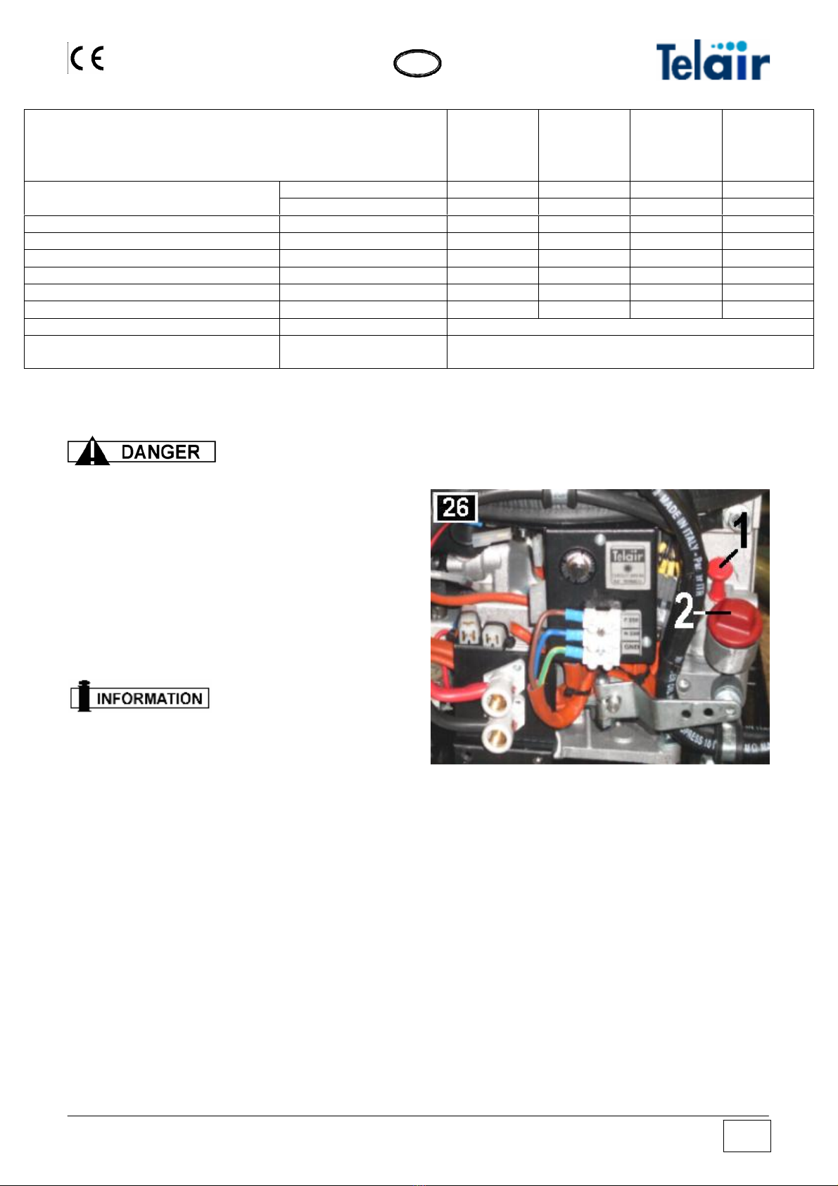
8.2.1 Checking the engine oil level
•Take the engine oil level dipstick out (fig. 26
ref. 1).
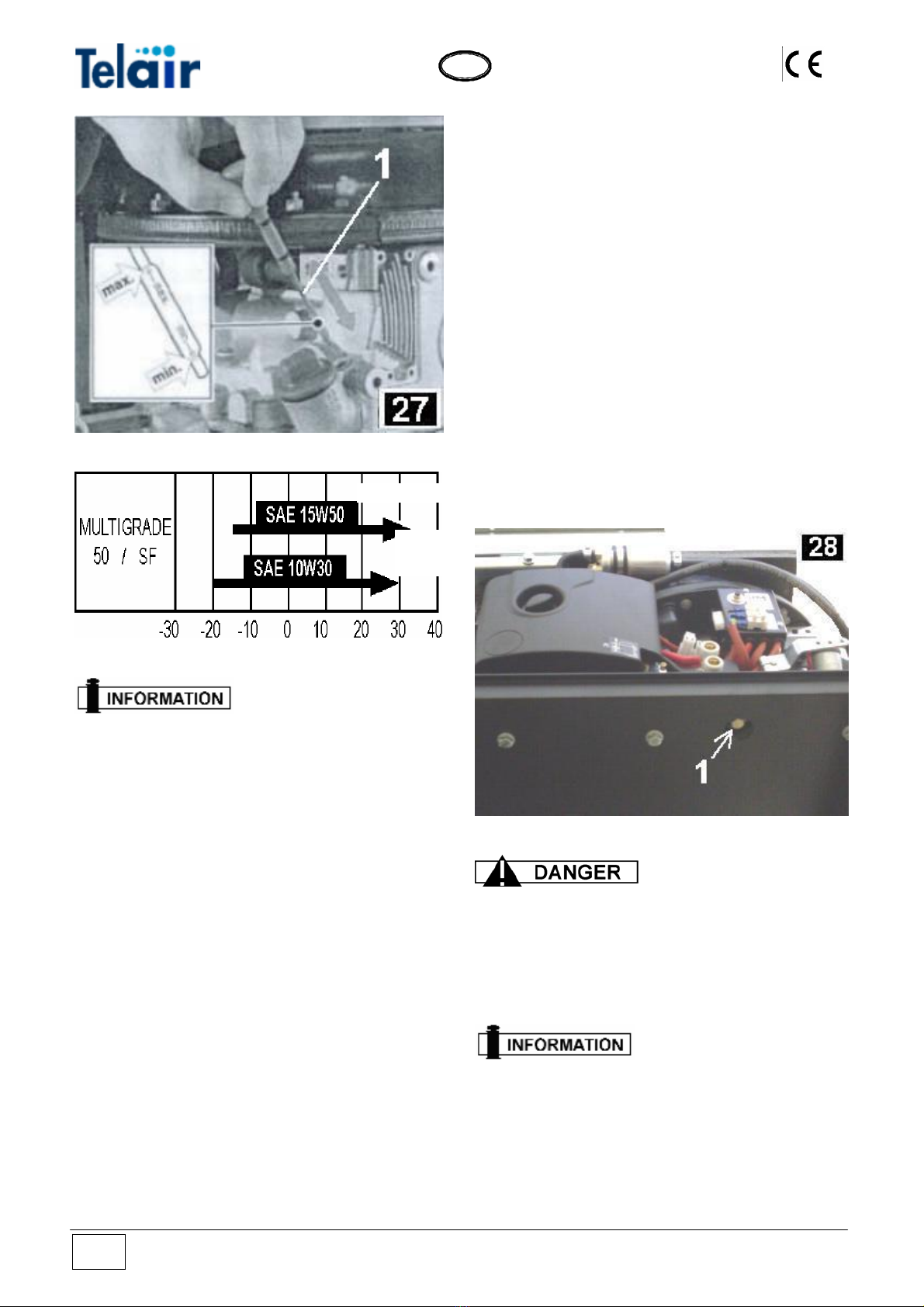
•Should the oil level be below the upper notch,
restore the oil level by adding the
recommended type of engine oil using the
suitable filler cap (fig. 27 ref. 1): (refer to the
engine user and maintenance manual).
Vers. 001 Energy 2510 D 17
G
B
All engine oil level
checking operations must be performed with
the generating set in a perfectly horizontal
position.
8.3 Maintenance operations to be carried out
by skilled personnel
To carry out certain servicing operations, it is
possible to extract the generating set from the
hood.
By means of the suitable key to open the lock,
remove the front door (fig. 16 ref. 3).
Then remove the bottom surface locking screw
(fig. 16 ref. 1) on both sides.
Take out the bottom surface with the engine all
the way to the mechanical stop (fig. 17).
If you wish to completely remove the engine
surface, screw out the setscrews (fig. 16 ref. 2)
too.
This will make it easier to obtain access to all the
inside parts of the generating set for unscheduled
maintenance or repair operations.
8.3.1 Engine oil replacement
Use multigrade detergent oil for Diesel engines
having a SAE viscosity degree suited to the
climate the generating set is working in (see table
and detailed instructions in the engine use and
maintenance manual).
To make it easier to drain the spent engine oil, it
is advisable to let the engine run for 3 to 5
minutes; in this way, the oil will be more fluid and
emptying will be quicker and more thorough.
Undo the special cap on the oil sump (fig. 28 ref.
1) and allow all the contained oil to be drained to
a collecting tank.
After doing this, screw the cap back on and
restore the oil level inside the engine sump, using
the filler cap (fig. 26 ref. 2).
Pour 0,95 lt. oil in the sump. Anyway, observe
the maximum level as indicated on the dipstick
(fig. 27 ref. 1).
For hot climates
For cold
climates
•Hot oil can scald.
•Causing the engine to run when the oil
level is too low can seriously damage it.
•Check the oil level after the engine has
been turned off.
Spent oil should not be
disposed freely in the environment but taken
to special disposal centres carrying out
disposal and/or recycling in compliance with
the applicable law provisions in force in the
country of use.
Energy 2510 D Vers. 001
18

G
B
8.3.2 Air filter maintenance
A clogged air filter will
reduce air flow to the carburettor. To prevent
carburettor malfunction, check the air filter
regularly. If the engine is used in a heavily
dusty environment, we suggest checking the
air filter every time before starting up the
engine.
Never use Diesel oil or
solvents with a low evaporation point for
cleaning the air filter cartridge, as this could
cause fires or explosions.
Never operate the engine without an air filter; the
engine would wear down quickly.
The filter element is located in a plastic box (fig.
29 ref. 1) To remove the filter element, open the
lid of the box by screwing out the suitable knob
(fig. 29 ref. 2).
After removing the lid, screw out the filter knob
(fig. 30 ref. 2) and take out the air filter (fig. 30
ref. 1).
Slightly beat the element on a hard surface to
remove the excess dust or blow compressed air
inside out (fig. 31 ref. 1). Never brush the filter
element, as this would push dust in between the
fibres. Replace the filter element if excessively
dirty.
Maintenance operations
must only be carried out after the engine has
been turned off.
Slightly beat the element on a hard surface to
remove the excess dust or blow compressed air
inside out (fig. 31 ref. 1). Never brush the filter
element, as this would push dust in between the
fibres. Replace the filter element if excessively
dirty.
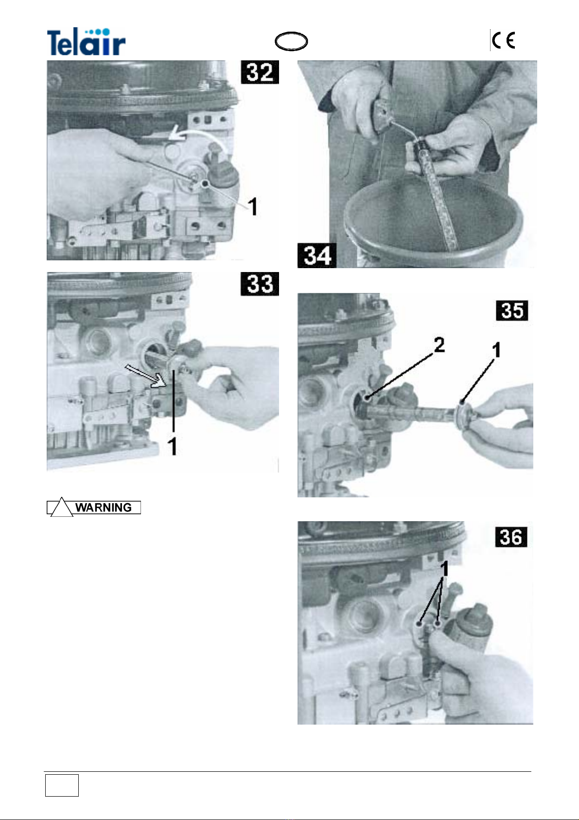
8.3.3 Oil filter maintenance
Perform oil filter
maintenance every 500 running hours
To clean the engine oil filter cartridge, this must
be removed from its seat.
Screw out the closing plug (fig. 32 ref. 1).
Take the filter out of its seat (fig. 33 ref. 1).
Vers. 001 Energy 2510 D 19
G
B
Scalding hazard due to
boiling oil. Spent oil should be collected and
disposed of without polluting the
environment in compliance with the
applicable law provisions in force.
Clean the oil filter cartridge by blowing
compressed air inside out. (fig. 34)
Check the sealing ring (fig. 35 ref. 2) for damage
and make sure it is properly fixed in its seat,
replace if necessary.
Check the sealing ring (fig. 35 ref. 1) for damage
and make sure it is properly fixed in its seat,
replace the oil filter if necessary.
Oil the sealing rings before fitting a new
cartridge.
Reassemble the oil filter pushing it all the way in
its seat (fig. 36 ref. 1) and screw back on again.
Energy 2510 D Vers. 001
20
Table of contents
Other Telair Portable Generator manuals


Popular Portable Generator manuals by other brands

Generac Power Systems
Generac Power Systems 005844-0 owner's manual

Lukasiewicz
Lukasiewicz Sonic Blaster Plus operating manual

Harvia
Harvia LTY45-U1 Instructions for installation and use

SANLI
SANLI GS720 manual

Generac Power Systems
Generac Power Systems 0595-0 owner's manual

Litionite
Litionite A250 user manual


SDMO
SDMO TECHNIC 15000 TE Instruction and maintenance manual

EBERBACH
EBERBACH E6003.00 manual

Champion Power Equipment
Champion Power Equipment 42432 Owner's manual & operating instructions

Agilent Technologies
Agilent Technologies E4428C user guide

Firman
Firman P03608 owner's manual

Craftsman
Craftsman 919.679501 instruction manual