USE AND CARE FOR CATALOG NUMBER:
- E6003.00 Shaker Power Unit
Variable Speed 60-260 rpm with Tachometer and Timer
115-230V 50/60Hz
GENERAL INFORMATION
oHandle this unit with care. Unpack and check that the contents coincide
with the packing-list. If any part is damaged or missing, please advise
the distributor immediately.
oDo not install or use this equipment without first reading this manual.
oThis manual should always be attached to the equipment and made
available to all users.
oNEVER TOUCH THE RECIPRICATING PORTION OF THE SHAKER
WHILE THE UNIT IS RUNNING!!
oIf you have any doubts or inquiries, please contact your supplier or
Eberbach Corporation technical service.
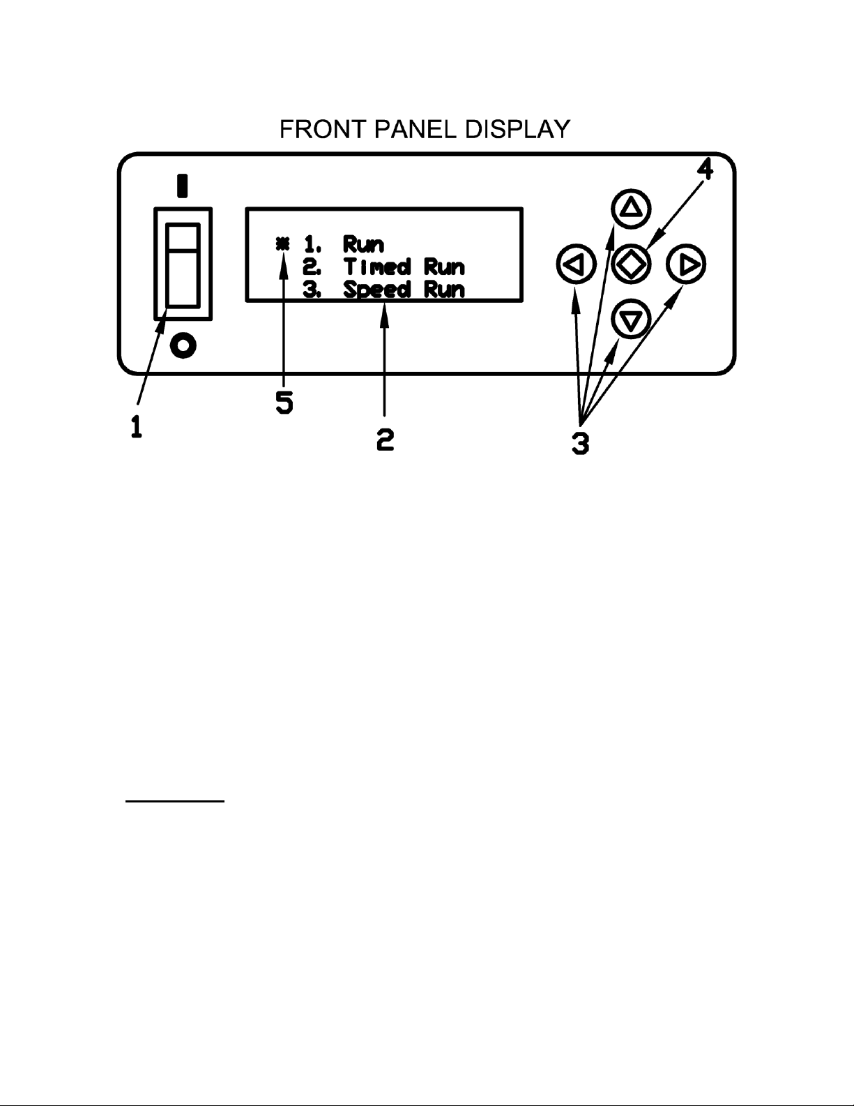
OPERATION
The Eberbach bench top reciprocating shaker (catalog E6003.00) features:
oA continuously variable speed range, adjustable between 60 and 260
osc/min with fixed stroke length set to 1.5” (38mm).
oA digital tachometer and programmable digital timer for simple and
accurate use.
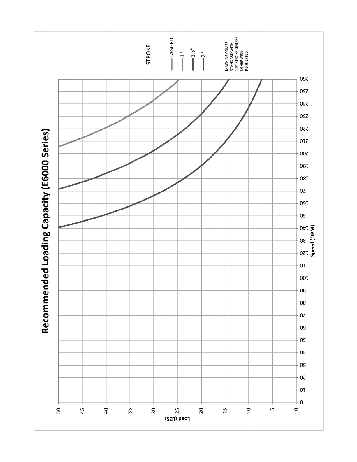
oA maximum shaking weight of 50lbs.
See the chart on the following page for the recommended loading capacity at
various speeds.