9
D_IN4 – the application of a high state triggers the activation of the welding process according to the preset
programme, whereas the application of low state, if a high state was previously applied at this input,
triggers the deactivation of the welding process (start/stop at level). NOTE Floating output – state
should be applied between D_IN4A and D_IN4B pins with any polarity.
D_OUT1 – a closed contact indicates generator standby (power supply on, scanning completed).
D_OUT2 – a closed contact indicates that the welding process is in progress.
D_OUT3 – a closed contact indicates that the scanning process is in progress.
D_OUT4 – a closed contact indicates that an error occurred.
24 V – 24 V DC / 1.5 A auxiliary power supply output which can be used to supply an external automation
system.
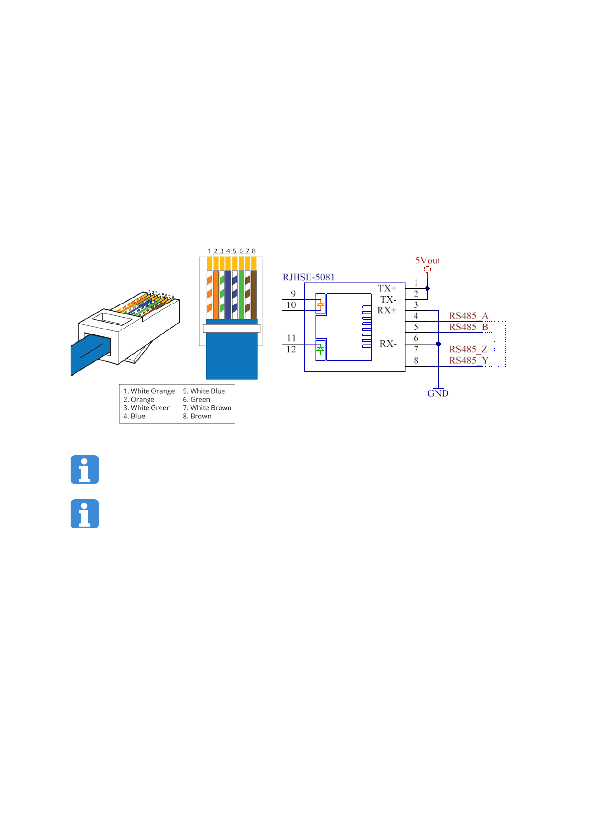
3.4. RS-485 MODBUS RTU communication interface
The generator is equipped with an RS-485 communication interface that supports MODBUS RTU transmission.
The I/O card has a RJ-45 connector, designated as RS-485. It is compatible with a UTP twisted pair. A connection
diagram is presented in Fig. 5.
Fig. 5 RJ-45 interface diagram and RS-485 interface cable and plug diagram
Transmission and reception lines are separated at this interface. To operate using RS-485, the appropriate
lines should be interconnected (as indicated with the broken line on the diagram). 5 V auxiliary output
voltage with a current efficiency of 100 mA is available at this interface.
To activate the MODBUS RTU communication unit, set the activity switch in the RS-485 position in the
SETTINGS menu to active (green) by clicking it.
MODBUS RTU:
RS-485/RS-422 transmission
Setup: 8 data bits, no parity, 1 stop bit
Bitrate: 9600 bps (to change, go to SETTINGS -> RS-485)
Generator address: 0xAA (to change, go to SETTINGS -> RS-485)
Available commands:
FC 03 – Read n setup registers
FC 04 – Read n input registers
FC 06 – Store one setup register
FC 16 – Store n setup registers
Register map:
Input registers (read-only, FC 04 command), numbers from 30001:
30001: uint16 status; status bit field: (adr:0)
GEN_IDLE 0x00 – Generator on standby, not welding
GEN_SCANNING 0x01 – Generator scanning
GEN_WELDING 0x02 – Generator welding
GEN_ERROR 0x03 – (Protection) error occurred