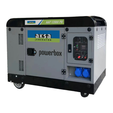
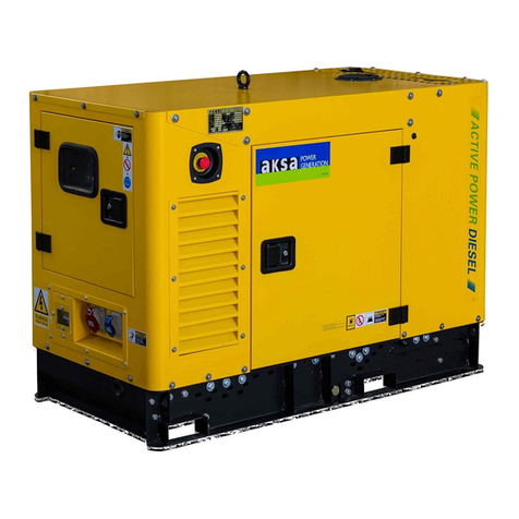
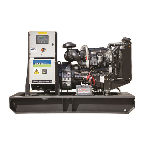
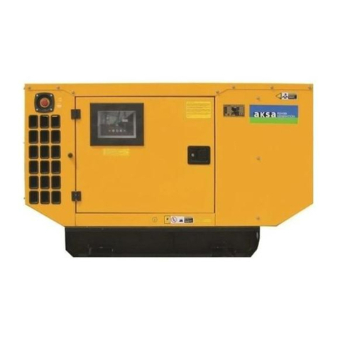
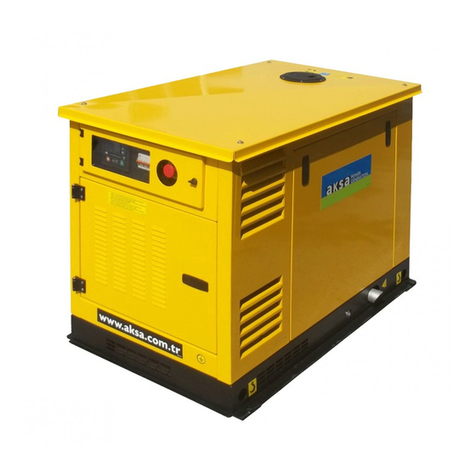
Aksa GE08TI User manual

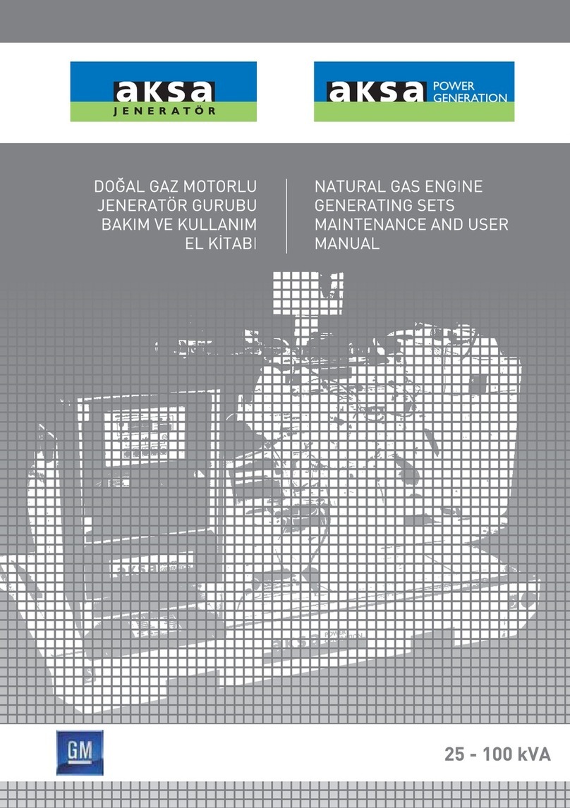
DOOSAN NATURAL GAS ENGINE
GENERATING SETS
MAINTENANCE AND
USER MANUAL

DOOSAN NATURAL GAS ENGINE
GENERATING SETS
MAINTENANCE AND USER
MANUAL
HEAD OFFICE
AKSA JENERATÖR SAN. A.Ş.
Rüzgarlıbahçe Mah. Özalp Çıkmazı No:10
34805, Kavacık - Beykoz / İSTANBUL
T : +90 216 444 4 630
F : +90 216 681 57 81
AUTHORIZED SERVICE
AKSA SERVICE & SPARE PARTS
Muratbey Beldesi, Güney Girişi Caddesi
No: 8 34540 Çatalca / ISTANBUL
T: +90 212 887 11 11
F: +90 2I2 887 10 20

DEAR AKSA GENERATOR SET USERS
Thank you for purchasing this quality-built Aksa Natural Gas Generator. When operated and maintained
according to the instructions in the operator’s manual, your Aksa generator will provide many years of
dependable service.
This manual is designed and developed to make you familiar with the generating system. Please read the fol-
lowing instructions carefully before starting to use your machine.
This manual contains safety information to make you aware of the hazards and risks associated with genera-
tor systems and how to avoid them.
Never operate, maintain or repair your generating set without taking general safety precautions.
The manufacturer reserves the right to change, alter or otherwise improve the system at any time without
prior notice.

1. INTRODUCTION .................................................................................................................. 1
2. GENERAL SAFETY PRECAUTIONS........................................................................................................... 2
2.1. General....................................................................................................................................................................... 2
2.2. Handling..................................................................................................................................................................... 2
2.3. Fire and Explosion................................................................................................................................................ 2
2.4. Mechanical................................................................................................................................................................ 3
2.5. Chemical.................................................................................................................................................................... 3
2.6. Noise ........................................................................................................................................................................... 3
2.7. Electrical..................................................................................................................................................................... 3
2.8. First Aid For Electric Shock............................................................................................................................. 4
3. GENERAL DESCRIPTION.................................................................................................... 5
3.1. Generator Set Description And Identification..................................................................................... 5
3.2. Generator Set Main Parts................................................................................................................................ 5
3.3. Natural Gas Engine.............................................................................................................................................. 6
3.4. Engine Electrical System.................................................................................................................................... 6
3.5. Cooling System...................................................................................................................................................... 6
3.6. Synchronous Alternator.................................................................................................................................... 6
3.7. Coupling..................................................................................................................................................................... 6
3.8. Base Frame............................................................................................................................................................... 6
3.9. Vibration Isolation ................................................................................................................................................ 6
3.10. Silencer And Exhaust System........................................................................................................................ 6
3.11. Control System...................................................................................................................................................... 6
4. ELECTRIC STARTING SYSTEM.......................................................................................... 7
4.1. Battery Systems ..................................................................................................................................................... 7
4.2. Maintenance Batteries........................................................................................................................................ 7
4.3. Battery Maintenance........................................................................................................................................... 7
4.4. Maintenance Free Batteries ............................................................................................................................ 7
4.5. Control of the Battery....................................................................................................................................... 7
4.6. Starting Aids............................................................................................................................................................. 7
5. HEALTHY AND SAFETY...................................................................................................... 7
5.1. Fire Protection........................................................................................................................................................ 7
5.2. Exhaust Gases......................................................................................................................................................... 8
5.3. Moving Parts............................................................................................................................................................ 8
5.4. Hazardous Voltages ............................................................................................................................................ 8
5.5. Water.......................................................................................................................................................................... 9
5.6. Coolant....................................................................................................................................................................... 9

6. WATER TREATMENT........................................................................................................... 9
6.1. General....................................................................................................................................................................... 9
6.2. Engine Coolant....................................................................................................................................................... 9
7. LUBRICATING OIL................................................................................................................ 9
7.1. Oil Performance Properties ........................................................................................................................... 9
7.2. Lubrication Oil Recommendations for Doosan Engines................................................................ 9
8. General precautions and controls which must be done before starting up the generating set.... 11
9. GENERATING SET CONTROL SYSTEMS....................................................................... 11
9.1. Control Panel.......................................................................................................................................................... 12
9.1.1. Control System P 732....................................................................................................................................... 12
9.1.2. Static Battery Trickle Charger........................................................................................................................ 13
9.2. Control System Options.................................................................................................................................. 13
9.2.1. Heaters....................................................................................................................................................................... 13
9.2.2. Speed/voltage control........................................................................................................................................ 13
10. General precautions and controls which must be done after starting up the generating set........ 13
11. GENERATING SET MAINTENANCE ............................................................................... 13
11.1. Maintenance Schedule For Gen-set........................................................................................................... 13
12. ENGINE TROUBLESHOOTING......................................................................................... 16
13. ALTERNATOR DESCRIPTION........................................................................................... 16
13.1. General....................................................................................................................................................................... 16
13.2. Construction and Components................................................................................................................... 16
13.3. Operation ................................................................................................................................................................. 17
13.4. Automatic Voltage Regulator........................................................................................................................ 17
14. VENTS AND DUCTS............................................................................................................. 17
15. MECCALTE ALTERNATOR TROUBLESHOOTING.................................................... 18
16. STORAGE OF THE GENERATOR................................................................................................. 18
16.1. Storage ..................................................................................................................................................................................... 18
16.2. Preparing for Operation After Storage.................................................................................................... 18
General precautions about warranty .......................................................................................................................
ATTACHMENTS
- CONTROL PANEL WIRING DIAGRAM
- AKSA JENERATÖR AUTHORIZED SERVICE POINTS
- AKSA JENERATÖR WHERE TO BUY ABROAD
- CERTIFICATIONS
- WARRANTY CERTIFICATE

1
1. INTRODUCTION
Aksa Generating set is designed to be commissioned,
when delivered, as soon as the necessary cooling wa-
ter, antifreeze, gas fuel, lubrication oil and fully charged
battery are provided. With its long years of experi-
ence, Aksa manufactures efficient; reliable and quality
generating set This user and maintenance manual is
prepared to assist the operator in operation and main-
tenance of the generating set. Observing the advices
and rules in this manual will ensure that the generating
set operates in maximum performance and efficiency
for a long time.
- Care should be taken to perform more frequent
maintenance in dirty and dusty environments in order-
to keep the generating set in good working condition,
- Necessary adjustment and repairs should be made
only by authorized and qualified persons.
- Each generating set has a model and a serial number
indicated on a label on the base frame. This plate also
indicates the manufacturing date, voltage, current pow-
er in kVA, frequency, power factor and weight of the
generating set. These data are necessary in spare part
orders, for warranty validity and for service calls.
Attach unit to base-frame with suitable diameter ma-
sonry anchor bolts long enough to retain the unit.
The generating set is designed to be safe when used
in correct manner. However responsibility for safety
rests with the personnel who install use and maintain
the set. If the following safety precautions are followed,
the possibility of accidents will be minimized. Before
performing any procedure or operating technique, it is
up to the user to ensure that it is safe.
The generating set should only be operated by person-
nel who are authorized and trained.
Only people that have the right skills should be allowed
to operate, adjust, perform maintenance or repair on
Aksa Power Generation equipment. It is the respon-
sibility of management to appoint operators with the
appropriate training and skill for each category of job.
Skill level I: Operator
An operator is trained in all aspects of operating the
unit with the push- buttons, and trained to know the
safety aspects.
Skill level 2: Mechanical technician
A mechanical technician is trained to operate the unit
the same as the operator. In addition, the mechani-
cal technician is also trained to perform maintenance
and repair, as describe in the instruction manual, and
is allowed to change settings of the control and safety
system. A mechanical technician does not work on live
electrical components.
Skill level 3: Electrical technician
An electrical technician has the same qualifications as
both the operator and the mechanical technician. In
addition, the electrical technician may carry out elec-
trical repairs within the various enclosures of the unit.
This includes work on live electrical components.
Skill level 4: Specialist from the manufacturer
This is skilled specialist sent by the manufacturer or its
agent to perform complex repairs or modifications to
the equipment In general it is recommended that not
more than two people operate the unit, more oper-
ators could lead to unsafe operating conditions. Take
necessary steps to keep unauthorized person away
from the unit and eliminate all possible source of dan-
ger at the unit.
The manufacturer does not accept any liability for any
damage arising from the use of non-original parts and
for modifications, additions or conversions made with-
out the manufacturer’s approval in writing,

2
2. GENERAL SAFETY PRECAUTIONS
2.I. GENERAL
1- The owner is responsible ‘for maintaining the unit
in a safe operating condition. Unit parts and accesso-
ries must be replaced if missing or unsuitable for safe
operation.
2- Operate the unit only for the intended purpose and
within its rated limits (pressure, temperature, speeds,
etc).
3- Gen-set and equipment shall be kept clean, i.e. as
free as possible from oil, dust or other deposits.
4- To prevent an increase in working temperature,
inspect and clean heat transfer surfaces (cooler fins,
intercoolers, water jackets, etc.) regularly.
5- Take precautions against fire. Handle gas fuel, oil
and anti-freeze with care because they are inflamma-
ble substances. Do not smoke or approach with naked
flame when handling such substances. Keep a fire-ex-
tinguisher in the vicinity.
WARNING
! Read and understand all safety precautions and warn-
ings before operating or performing maintenance on
the generating set.
! Failure to follow the instructions, procedures, and
safety precautions in this manual may increase the pos-
sibility of accedents and injuries.
! Do not attempt to operate the generating set with a
known unsafe condition.
! If the generating set is unsafe, put danger notices and
disconnect the battery negative (-) lead so that it can-
not be started until the condition is corrected.
! Disconnect the battery negative (-) lead prior to at-
tempting any repairs for cleaning inside the endosure.
! Install and operate this generating set only in full com-
pliance with relevant National, Local or Federal Codes;
Standards or other requirements.
2.2. HANDLING
The following safety precautions should be noted:
WARNING
! Make electrical connections in compliance with rele-
vant Electrical Codes; Standards or other requirements.
This includes requirements for grounding and ground/
earth faults.
! Engine exhaust emissions are hazardous to personnel.
The engine exhaust for all indoor generating sets must
be piped outdoors via leak-free piping in compliance
with relevant Codes, Standards and other require-
ments. Ensure that hot exhaust silencers and piping are
clear of combustible material and are guarded for per-
sonnel protection per safety requirements. Ensure that
furmes from the exhaust outlet will not be a hazard
! Never lift the generating set by attach-
ing to the engine or alternator lifting lugs,
instead use the lifting points on the base
ame or canopy.
! Ensure that the lifting rigging and sup-
porting structure is in good condition
and has a capacity suitable for the load.
! Keep all personnel away from the generating set
when it is suspended.
2.3. Fire and Explosion
Warning
• Natural Gas is extremely ammable and explosive.
• Fire or explosion can cause severe burns or death.
• Install the gas fuel supply system according to appli-
cable fuel-gas codes.
• Before placing the generator into ser-
vice, the fuel system lines must be prop-
erly purged and leak tested.
• After the generator is installed, you
should inspect the gas fuel system periodically.
• NO leakage is permitted.
• DO NOT operate engine if smell of fuel is present or
other explosive conditions exist.
• DO NOT smoke around the generator.Wipe up any
oil spills immediately. Ensure that no combustible ma-
terials are left in the generator compartment Keep the
area near the generator clean and free of debris.
However, safety dictates that fully charged BC and ABC
re extinguishers are kept on hand. Personnel must
know how to operate them.
WARNING
! Ensure that the generating set room is properly ven-
3
tilated.
! Keep the room, the oor and the generating set clean.
When spills of oil, battery electrolyte or coolant occur,
they should be cleaned up immediately.
! Do not smoke or allow sparks, ames or other sourc-
es of ignition around gas line or batteries.
! Turn off or disconnect the power to the battery char-
ger before making or breaking connections with the
battery.
! To avoiding arcing keep grounded conductive objects
(such as tools) away from exposed live electrical parts
(such as terminals).
2.4. Mechanical
The generating set is designed with guards for pro-
tection from moving parts. Care must still be taken to
protect personnel and equipment from other mechan-
ical hazards when working around the generating set
WARNING
! Do not attempt to operate the generating set with
the safety guards removed.While the generating set is
running do not attempt to reach
under or around the guards to
do maintenance or for any other
reason.
! Keep hands; arms, long hair, loose clothing and jewelry
away from pulleys, belts and other moving parts.
Attention: Some moving parts cannot be seen clearly
when the set is running.
! If equipped keep access doors on enclosures closed
and locked when not required to be open.
! Avoid contact with hot oil, hot coolant hot surfaces
and sharp edges and corners.
! Wear protective clothing includ-
ing gloves and hat when working
around the generating set.
! Do not remove the radiator ller
cap until the coolant has cooled.
Then loosen the cap slowly to relieve any excess pres-
sure before removing.
2.5. Chemical
Oils, coolants, lubricants and battery electrolyte used in this
generating set are typical of the industry. However, they can
be hazardous to personnel if not treated properly.
WARNING
! Do not swallow or allow skin contact with oil, cool-
ant lubricants or battery electrolyte. If swallowed, seek
medical treatment immediately.
! Do not wear clothing that has been contaminated
by lube oil.
! Wear an acid resistant apron and lace shield or gog-
gles when servicing the battery.
If electrolyte is spilled on skin or
clothing ush immediately with large
quantities of water.
2.6. Noise
Generating sets that are not equipped with sound
attenuating enclosures can produce
noise levels in excess of 105 dB(A).
Prolonged exposure to noise lev-
els above 85 dB(A) is hazardous to
hearing.
WARNING
Ear protection must be worn when operating or work-
ing around an operating generating set.
2.7. Electrical
Effective and safe operation of electrical equipment,
it is only ensured by the correct placement, use and
maintenance of equipment.
WARNING
! The generating set must be connected to the load
only by trained and qualied electricians who are au-
thorized to do so, and in compliance with relevant
Electrical Codes, Standards and other regulations.
! Ensure that the generator set is effectively earthed/
grounded in accordance with all relevant regulations
before starting.
! The generating set should be shutdown with the
battery negative (-) terminal disconnected prior to at-
tempting to connect or disconnect load connections.
! Do not attempt to connect or disconnect load con-
nections while standing in water or on wet or soggy
ground.

4
! Do not touch electrically energized
parts of the generating set and/or in-
terconnecting cables or conductors
with any part of the body or with
any non insulated conductive object.
! Replace the generating set terminal box cover as
soon as connection or disconnection of the load ca-
bles is complete. Do not operate the generating set
without the cover securely in place.
! Connect the generating set only to loads and/ or
electrical systems that are compatible with its elec-
trical characteristics and that are within its rated ca-
pacity.
! Keep all electrical equipment clean and dry. Replace
any wiring where the insulation is cracked, cut abrad-
ed or otherwise degraded, Replace terminals that are
worn, discolored or corroded. Keep terminals dean
and tight
! Insulate all connections and disconnected wires.
! Use only Class BC or Class ABC extinguishers on
electrical res.
2.8. First Aid For Electric Shock
WARNING
! Do not touch the victim’s skin with bare hands until
the source of electricity has been turned off.
! Switch off power if possible otherwise pull the plug
or the cable away from the victim.
! If this is not possible, stand on dry insulating material
and pull the victim clear of the conductor, preferably
using insulated material such as dry wood.
! If victim is breathing, moving the victim away from
conductor, preferably using insulated material such as
dry wood.
! If victim is breathing, turn the victim into the recov-
ery position described below. If victim is unconscious,
perform resuscitation as required;
Open the airway
Tilt the victim’s head back and lift the
chin upwards. Remove objects from
the mouth or throat (including false
teeth, tobacco or chewing gum).
Breathing
Check that the victim is
breathing by looking, listening
and feeling for the breath.
Circulation
Check for pulse in the victim’s neck.
If no breathing but pulse is present
• Pinch the victim’s nose rmly.
• Take a deep breath and seal your lips around the
victim’s lips.
• Blow slowly into the mouth watching for the chest
to rise.
• Let the chest fall completely.
Give breaths at a rate of 10 per minute.
• If the victim must be left to get help, give 10 breaths
rst and then return quickly and continue.
• Check for pulse after every 10 breaths. When
breathing restarts, place the victim into the recovery
position described later in this section.
If no breathing and no pulse
• Call or telephone for medical help.
• Give two breaths and start chest
compression as follows:
• Place heel of hand 2 ngers breadth
above ribcage/breastbone junction.
• Place other hand on top and inter-
lock ngers,
• Keeping arms straight, press down
4-5 cm at a rate of 15 times per min-
ute.
• Repeat cycle (2 breaths and 15 compressions) until
medical helps takes over.
• If condition improves, conrm
pulse and continue with breaths.
Check for pulse
after every 10 breaths.
• When breathing restarts, place the victim into the
recovery position described below.
Recovery position
• Turn the victim onto the side.
• Keep the head tilted with the jaw
forward to maintain the open airway.
• Make sure the victim cannot roll
forwards or backwards.
• Check for breathing and pulse regularly. If either
stops, proceed as above.
WARNING
! Do not give liquids until victim is conscious.

5
3. GENERAL DECRIPTION
3.1. Generating Set Description and Identification
Natural gas generators are independent units for the
production of electric power basically; they comprise
a constant voltage synchronous driven by a gas engine.
The sets are used for two main purposes;
a- Continuous duty sets,
Used to produce electric power for countless require-
ments (motive power, lighting heating etc) in areas
where other sources or power are unavailable.
b- Emergency duty sets,
Used during public network failures, when such failures
are liable to cause serious trouble to persons or mate-
rial or financial damage (i.e. in hospitals, industrial plants
with non-stop operating cycles, etc) or to meet peak
energy demands.
According to their application, the sets are further di-
vided into:
• set for use on land
The sets for use on land can be
• stationary sets (fixed installation),
These sets are available in a vast range of versions, for
every operating requirement the main ones being:
01. hand control generating sets
02. stand-by generating sets
The standard stationary generating set comprises;
• natural gas engine
• synchronous generator
• coupling
• metal sub-base with vibration isolators
• starter batteries
• instrument panel
• exhaust gas silencer.
Aksa Generating Set has been designed as a complete
package to provide superior performance and reliabil-
ity. Figure. 3.1. identifies the major components. This
figure is of atypical generating set. However, every set
will be slightly different due to the size and configu-
ration of the major components. This section briefly
describes the parts of the generating set. Further in-
formation is provided in later sections of this manual.
Each generating set is provided with a Rating Label
(item I) generally fixed to the base frame. This label
contains the information needed to identify the gener-
ating set and its operating characteristics. This informa-
tion includes the model number, serial number, output
characteristics such as voltage and frequency, output
rating in kVA and kW, product date and weight.
The model and serial numbers uniquely identify the
generating set and are needed when ordering spare
parts or obtaining service or warranty work for the set
Aksa generating sets are an Alternating Current gen-
erator, built for continuous running at sites where no
electricity is available (some models are excepted) or
as stand-by in case of interruption of the mains.
The generator operates at 50 Hz 230/220 V. in line-
to-neutral mode and 400/380 V in line-to-line mode.
3.2. Generating Set Main Parts
Figure 3.1.Typical Engine Generator Set
No Description
1 Aksa Generating Set Rating Label
2 Natural Gas Engine
3 Air Filter
4 Radiator
5 Alternator
6 Terminal Box
7 Base Frame
8 Control Panel

6
3.3. Natural Gas Engine
The natural gas engine powering the generating set
(Item 2) has been chosen for Its reliability and the fact
that it has been specifically designed for powering gen-
erating sets. The engne is of the heavy duty industrial
type with 4 stroke and is fitted with all accessories to
provide a reliable power supply. These accessories in-
clude, among others, a cartridge type dry air filter (item
3) and an electronic engine speed governor. The en-
gine cylinder block is cast in one piece cast iron, vertical
cylinders inline overhead valves and camshaft in block.
The cylinder heat is made of special cast iron. The ther-
mally loaded flame plate is efficiently water cooled. The
crankshaft is forged in one piece in a high tensile steel.
Lubrication: forced lubrication via gear pump, special
paper cartridge -type filters, lubricant cooling via heat
exchanger on most versions.
3.4. Engine Electrical System
The engine electrical system is 24 VDC negative
ground/earth. This system includes an electric engine
starter, a battery and a battery charging alternator.
For 24 volts electrical system two batteries are given.
Other types of batteries may be fitted If they were
specified.
3.5. Cooling System
The engine cooling system is water cooled. The water
cooled system is comprised of a radiator (Item 4) a
pusher fen and thermostat. The alternator has its own
internal fan to cool the alternator components.
3.6. Synchronous Alternator
Horizontal axle alternator (synchronous three phase),
on rolling bearings, self-ventilated within the room with
low-loss silicon-sheet stator bundle, electrolytic copper
winding with dass H insulation.
The output electrical power is normally produced by a
screen protected and drip-proof, self-exciting, self reg-
ulating, brushless alternator. (Item 5) Fine tuned to the
output of this generating set. Mounted on top of the
alternator is a sheet steel terminal box (Item 6).
3.7. Coupling
Engine and alternator are firmly joined by a coupling
cone that guarantees the proper assembly coaxiality
Mono-support machines are aiso used a special flexible
disk is used in place of a flexible coupling.
3.8. Base frame
The engine and alternator are coupled together and
mounted on a heavy duty steel base-frame (Item 7).
3.9. Vibration Isolation
The generating set is fitted with vibration isolators
which are designed to reduce engine vibration being
transmitted to the foundation on which the generating
set is mounted. These isolators are fitted between the
engine /alternator feet and the base frame.
3.10. Silencer and Exhaust System
Exhaust gases from the turbocharger are discharged
toward atmosphere through a silencer. These should
be vented as high as possible, and must be prevented
from re-entering the engine via the charge air intake, or
polluting the radiator fins.
It is important to note that the turbocharger nozzles
must be always free of loads. Stainless steel exhaust
compensator(s) is delivered with generator set. Ex-
haust lines of different engines shall not be mixed in
a common stack, but routed separately in individual
ducts, enclosed in a chimney.
Suitable material is carbon steel sheet, and recom-
mended calculation temperature is 475°C. Rain and
condensate permanent draining shall be provided to
prevent water entering the silencer and the engine.
An exhaust silencer is provided loose for installation
with the generating set. The silencer and exhaust sys-
tem reduce the noise emission from the engine and
can direct exhaust system reduce the noise emission
from engine and can direct exhaust gases to safe out-
lets. The exhaust silencer is made of a carbon steel re-
ceiver containing sound attenuator and wave de-phas-
ing system made of perforated steel sheet and heavy
rock wool. It is asbestos-free. The exhaust silencer is
delivered in two configurations with an industrial atten-
uation and residential attenuation.

7
3.11. Control System
One of several types of control systems and panels
(item 8) may be fitted to control the operation and
output of the set and to protect the set from possi-
ble malfunctions. Section I I of this manual provides
detailed information on these systems and will aid in
identification of the control system fitted on the gen-
erating set.
4. ELECTRIC STARTING SYSTEMS
Electric starting systems are generally used on all gen-
sets.
The power source for electric starting systems is a
24VDC battery system. Control of starting is via a start
solenoid which is controlled by the gen-set control
system.
4.1. Battery Systems
Battery type is lead acid. Lead acid batteries are gener-
ally used, being the least expensive.
4.2. Maintenance Batteries
Warning
• Do not smoke or allow sparks, flames or other
sources of ignition around batteries. Hydrogen gas
generated by charging batteries is explosive.
• Wear an acid resistant apron and face shield or gog-
gles when servicing the battery. If electrolyte is spilled
on skin or clothing, flush immediately with large quan-
tities of water.
• Take out the metallic things in your wrist and protect
your wrist and hand.
• Disconnect the battery negative (earth) lead first and
reconnect last.
• Always ensure that battery charging is carried out in
a well ventilated area.
The starting batteries should be located as close as
possible to the generating set while still being accessi-
ble for servicing. This will prevent electrical losses.
4.3. Battery Maintenance
• Keep the top of the battery and its terminals clean.
• Cover the battery terminals and its connections with
Vaseline.
• Tighten the terminals but not tighten it hardly.
• Control the electrolyte level periodically. It must be
10 mm above the plates.
• Control the abrasion in the charge alternator belt
and check periodically the belt tension according to
producer’ recommendation.
• Ensure that your battery is not uncharged.
4.4. Maintenance Free Batteries
Ensure that all battery connections are correct and
batteries are always charged. After that there is not
any procedure for this battery.
4.5. Control of the Battery
Conduct an inspection every time before testing the
battery.
1. A white powdered element causes abrasion to the
pole-heads, its connections. Remove the connections
and wash them with hot water to purify the oxidation.
Reconnect it and coat with vaseline.
2. Check if any un-tightened connections exist.
4.6. Starting Aids
It is customary to maintain coolant temperatures above
40°C min. to promote quick starting on an emergency
generating set and to take the load. Thermostatical-
ly controlled immersion heaters, deriving their supply
from the primary source of power are fitted in the
engine cooling system to provide this heating. Heater
warms up the jacket water of the engine when the
generating set is not working.
5. HEALTY and SAFETY
Safety should be the primary concern of the facility de-
sign engineer and all personnel engaged on installation
and commissioning. Safety involves two aspects:
1) Safe operation of the generator itself (and its ac-
cessories).
2) Reliable operation of the system.
Reliable operation of the system is related to safety
because equipment affecting life and health, such as
life support equipment in hospitals, emergency aggress
lighting, building ventilators, elevators and fire pumps,
may depend on the generator set.

8
5.1. Fire Protection
The design, selection and installation of fire protection
systems require the following considerations:
• The fire protection system must comply with the
requirements of National Standards.
• Typically, the generator room will be required to
have a one hour fire resistance rating. Generator room
construction will have to have a two hour fire resis-
tance rating.
• Generator room shall not be used for storage pur-
poses.
• The authority may specify the quantity, type and siz-
es of approved portable fire extinguishers required for
the generator room.
• A manual emergency stop station outside the gener-
ator room or enclosure or remote from the generator
set in an outside enclosure would facilitate shutting
down the generator set in the event of a fire or anoth-
er type of emergency.
General
• Do not permit any flame, cigarette, pilot light, spark,
arcing equipment, or other ignition source near the
generating set or fuel line.
• Fuel lines must be adequately secured and free of
leaks. Fuel connection at the engine should be made
with an approved flexible line.
• Be sure all fuel supplies have a positive shut-off.
5.2. Exhaust Gases
• Be sure the exhaust system will properly dispel dis-
charged gases a way from enclosed or sheltered areas
and areas where individuals are likely to congregate.
• Never connect the exhaust system of two or more
engines.
• Never discharge engine exhaust into a brick, tile or
cement block chimney, or a similar structure. Exhaust
pulsations could cause severe structural damage.
• Do not use exhaust gases to heat a compartment.
• Be sure that the unit is well ventilated.
• Ensure that there is independent support for the ex-
haust system. No strain should be imposed on the en-
gine exhaust manifolds. Which is especially important
on a turbo-charged engine.
5.3. Moving Parts
• Tighten supports and keep guards in position over
fans drive belts etc. Make sure that fasteners on the
set are secure.
• Keep hands, clothing and jewellery away from mov-
ing parts.
• If adjustment must be made while the unit is running,
use extreme caution around hot manifolds, moving
parts, etc.
5.4. Hazardous Voltages
Improper wring can cause fire or electrocution, result-
ing in severe personal injury or death and property or
equipment damage.
For personal protection, stand on a dry wooden plat-
form or rubber insulating mat, make sure clothing and
shoes are dry, remove jewellery from hands and use
tools with insulated handles.
• Do not leave cables trailing on the engine room floor.
• Do not use the same trunking for electric cables and
water lines.
• Do not run AC and DC cables in the same looms
or trunking
• Always ensure that bonding and equipment earthing
are correctly done. All metallic parts that could be-
come energised under abnormal conditions must be
properly earthed.
• Always disconnect the batteries and battery charger
when serving or carrying out maintenance particular-
ly on equipment arranged for automatic mains failure
operation. Always disconnect a battery charger from
its AC source before disconnecting the battery cable.
Accidental starting of the generator set while working
on it can cause severe personal injury or death.
• Do not tamper with interlocks.
• Do not connect the generator set directly to any
building electrical system.
• Always follow all applicable state and local electrical
codes. Have all electrical installations performed by a
qualified licensed electrician.
High voltage sets work differently to low voltage ones.
Special equipment and training is required to work
around high voltage equipment. Operation and main-
tenance must be done only by persons trained and
qualified to work on such devices. Improper use or

9
procedures may well result in personal injury or death.
• Do not work on energised equipment. Unautho-
rised personnel must not be permitted near energised
equipment. Due to the nature of high voltage electrical
equipment includes voltage remains after the equip-
ment is disconnected from the power source. Equip-
ment should be de-energised and safety earthed.
5.5.Water
Water or moisture inside a generator increases the
possibility of “ flashing” and electrical shock, which can
cause equipment damage and severe personal injury
or death. Do not use a generator which is not dry
inside and out.
5.6. Coolant
The coolant heater must not be operated while the
cooling system is empty or when the engine is running
or damage to the heater will occur. Coolant under
pressure have a higher boiling point than water.
• Do not open a radiator, pressure cap while the en-
gine is running. Allow the generator set to cool and
bleed the system pressure first.
6.WATER TREATMENT
6.1. General
The engine cooling system is subject to rust and cavita-
tion attacks. To minimize the severity of this condition
an anti-corrosive agent can be added to totally clean
and limpid coolant water.
An antifreeze solution is also required to prevent
freezing of the coolant in the cold weather.
6.2. Engine Coolant
Water for coolant should be clean and free from any
corrosive chemicals such as chlorides, sulphates and
acids. It should be kept slightly alkaline with a pH value
in the range 8,5 to 10,5.
Generally, any water which is suitable for drinking can
be used, with treatment as described below.
Protection against corrosion
Supplemental Coolant Additive is required to protect
the cooling system from fouling, solder blooming and
general corrosion.
The use of antifreeze is also recommended as DCA4
concentrations are dependent upon the presence of
antifreeze. Antifreeze also interacts with DCA4 to pro-
vide greater corrosion and cavitation protection.
Procedure for Treating Coolant
1. Add the required amount of water to mixing con-
tainer and dissolve in the required quantity of DCA4
2. Add the required amount of antifreeze, if used, to
the water solution and mix thoroughly.
3. Add the coolant to the cooling system
Cold Weather Protection
Antifreeze must be added to the coolant where there
is any possibility of freezing to protect the engine from
damage due to coolant freezing.
The engine cooling water can be used diluting it with
antifreezing solution 40% and the additive for rust pre-
vention (DCA4) 3 ~ 5 %. The dosage of DCA4 must
be increased to higher concentration if antifreeze is
not added to the coolant A low - silicate antifreeze is
recommended.
The density of antifreezing solution and additive for
rust prevention is able to be confirmed by the cooling
water test kit
• Amount of Anti-freeze in winter
Ambient
Temperature (°C)
Cooling water
(%)
Anti-freeze
(%)
Over- 10
-10
-15
-20
-25
-30
-40
85
80
73
67
60
56
50
15
20
27
33
40
44
50
7. LUBRICATING OIL
Oil system of diesel engine is one of the most import-
ant elements of the engine. Correctly made engine
overhaul (this subject includes oil change periods, filter
change periods, paying attention about selecting the
true type of oil) prolongs the life cost of the engine.
7.1. Oil Performance Properties
The American Petroleum Institute (API) the American
Society for Testing and Materials (ASTM) and Society
of Automotive Engineers (SAE) has developed and
preserved a system in order to classify the lubrication
oils for their performance categories.
7.2. Lubrication Oil Recommendations for Doosan
Engines
• The following oils are also recommended
SAE API No. Sulfated ash content
I5W40 above CD or CE Bellow 0.5 %
Recommend oil: TOTAL LMG-405
Mobil Delvac super GEO I5W40

10
Engine Oil Capacity
Engine model In oil pan Totoal
(liter)
Max.
(liter)
Min.
(liter)
GE08TI
GEI2TI
GVI58TI
GVI80TI
GV222TI
23
30
28
35
40
17
24
26
28
33
25
33
31
38
43
• Engine oil should be changed at the specified inter-
vals. Oil in the oil filter cartridge should be changed
simultaneously.
First oil change After 50hours operating
Engine
Model
GE08TI
GEI2TI
GVI58TI
GVI80TI
GV222TI
Every 200 hours
Engine oil viscosity - ambient temperature
Fig.7.1. Recommended SAE Oil Viscosity Grades v.s.
Ambient Temperatures

11
Generating Set, 50 Hz, 400 V
Coolan
Capacity
Coolan
Capacity
Oil Specications
Not; Lubricating oil viscosity level will be chosen
from Figure 7.1 according to the ambient
temperature
Model
Standby
Power
kVA
Doosan
Engine
Model Liter Liter
ADG 158
ADG 2I0
ADG 274
ADG 350
ADG 428
158
210
274
350
428
GE08TI
GE12TI
GV158TI
GV180TI
GV222TI
144
147
192
238
270
25
33
31
38
43
API CH
API CI-4
API CF-4
Table 7.1. Coolant lubricating oil capacities and lubricating oil specications.
8. GENERAL PRECAUTIONS AND CONTROLS
WHICH MUST BE DONE BEFORE STARTING UP
THE GENERATING SET.
• Make a general visual inspection on the engine and
alternator. Check if there is any breakage, crack, inden-
tation, leakage or looseness. Never operate the gene-
rating set before removing any fault, if any.
•Take out foreign materials such as keys, tools, cleaning
wool, papers etc. on the engine and the alternator.
• Never operate the generator in a humid atmosphe-
re. Excessive moisture causes worsening of the gene-
rator insulation.
• Never operate the generator in excess of its limits as
indicated in the technical specications and avoid long
no-load sequences.
• Check the lubrication oil level on the dipstick. Rell
with an appropriate oil if it is low. Oil level normally
must be close to the maximum level line.
• Look at the water level by opening the radiator tap.
If it is inadequate add more water.Water level must be
30 mm lover than the water lling neck.
• Engine cooling water must include antifreeze accor-
ding to the coolest weather conditions in the area. A
mixture of 50% antifreeze and 50% water provides a
good protection in all area.
• Inspect the radiator air outlet hood, open if clogged
and clear away all obstructions in front of the air outlet.
• Check the air lter gauge. Clean or replace air lter,
if necessary.
• Keep the inlet opening open.
• Make sure that the generating set can easily take air
from the environment.
• Check the battery connection cables. Take care to
tighten the loosened battery terminals with spanner
and, cover with special substance and keep clean in
order to avoid oxidation.
• Open the battery caps and check the liquid level
in the cells for maintenance type battery. Add distilled
water, if necessary, so as to be 1cm higher than the se-
paration. Never ll the cells with tap water, acid water
or acid.
• Check generator case grounding. When the genera-
tor is installed in a moist place or on a highly conduc-
tive material such as plate iron or steel work, be sure
to connect a grounding conductor to the grounding
terminal provided near the output terminal block and
bury the conductor deep in the ground securely (at
a depth of 50 cm or more from the ground surface).
• Check bolts and nuts for looseness and tighten them
• Check electrical wiring for disconnection, short and/
or terminal looseness.
• Check if the circuit breaker outlet switch is in OFF
position.
• Make sure that the emergency stop button is not
pressed.
9. GENERATING SET CONTROL SYSTEMS
To control and monitor the generating set, an electro-
nic control system has been used.
P 732 control system is tted the generating sets.
Control panel provides a means of starting and stop-
ping the generating set, monitoring its operation and
output and automatically shutting down the set in the
event of critical condition arising such as low oil pres-
sure or high engine temperature.

12
9.1. Control Panel
Control, supervision and protection panels are moun-
ted on the generator base frame.
9.1.1. Control System P 732
The control panel is equipped as follows:
Equipments:
- Control with DSE, model 7320 module
- Static battery charger
- Emergency stop push button.
Control Module DSE 7320 Features
• The module monitors a mains supply and controls a
standby generating set with automatic transfer switch
• Module indicates operational status and fault conditi-
ons by means of its LCD display
• Microprocessor controlled
• Front panel programming and also via PC software
• 132 x 64 pixel LCD display makes information easy
to read
• Front panel programming and also via PC software
• Soft touch membrane keypad and ve key menu
navigation
• Remote communication via RS 232, RS 485 and Et-
hernet and SMS messaging
• Event logging (50) showing date and time
• Multiple date and time engine exercise mode and
maintenance scheduler
Controls
Stop - Manual - Auto - Test - Start - Mute/Lamp test
- Transfer to generator - Transfer to mains - Menu na-
vigations buttons
Instruments via LCD display Engine
• Oil pressure (PSI & Bar)
• Temperature (°C & °F)
• Speed RPM
• Run time
• Maintenance due
• Battery volts
Generator
• Volts (L-L / L-N)
• Currents (LI, L2, L3)
• Frequency (FHz)
• kW
• Cos cp
• kVA, kVAr
• kWh, kVAh, kVArh
• Phase sequence
Mains
• Volts (L-L / L-N)
• Frequency (FHz)
Protections
Warning
- Charge failure
- Battery under voltage
- Fail to stop
- Low fuel level (opt.)
- kW over load
- Negative phase sequence
Pre-alarms
- Low oil pressure
- High engine temperature
- Low engine temperature
- Over/Under speed
- Under/over generator frequency
- Under/over generator voltage
- ECU warning
Shut Downs
- Fail to start
- Emergency stop
- Low oil pressure
- Low coolant level
- Over/Under speed
- Under/over generator frequency
- Under/over generator voltage
- High engine temperature
- Oil pressure sensor open
- Phase rotatio
Electrical trip
- Earth fault
- kW over load

13
- Generator over current
- Negative phase sequence
LED indication
- Mains available
- Mains on load
- Generator available
- Generator on load
9.1.2. Static Battery Trickle Charger
This charger is designed to ensure that the starter bat-
teries maintain their charge even if the generating set is
not operated for long periods.
As an option, a battery charger ammeter may be tted
to the control panel in order for the operator to mo-
nitor the functioning of the battery charger.
9.2. Control System Options
A large variety of options may be tted to customize
the control system to a specic installation.
9.2.1. Heaters
Alternator anti-condensation heaters may be tted to
the alternator stator winding to keep them dry in hu-
mid conditions.
Panel anti-condensation heaters may be tted in the
control panel to keep moisture levels down.
9.2.2. Speed/Voltage Control
Two controls may be tted to adjust the speed or vol-
tage of the generating set: Speed Adjust Potentiometer,
and Voltage Adjust Potentiometer. Speed adjust poten-
tiometer uses electronic governor control system.
10. GENERAL PRECAUTIONS AND CONTROLS
WHICH MUST BE DONE AFTER STARTING UP
THE GENERATING SET
• Whenever an abnormal conditions arises, e.g. exces-
sive vibration, noise, odour, etc., switch the circuit bre-
akers to OFF and stop the engine. Correct the faulty
condition before restarting
• Never touch the power terminals during operation
of the machine.
• Check if the exhaust system has any leakage.
• Check for leakage of oil or cooling water.
• Monitor the generating set operation by means of
the control module LCD display. Check the engine
temperature and oil pressure. Oil pressure must reach
the normal value 10 seconds after the generating set
operation.
• Monitor the generating set outlet voltage and fre-
quency by means of the control module LCD display.
Check the voltage, if the voltage between phases is
400 V. and between phase and neutral is 230 V. Check
that the frequency is 50 Hz on generating sets with
electronic governors.
• If an engine block water heater is not available, run
the generating set at no-load for 8 minutes and when
the engine warm than apply on load (for manual mo-
dels) Apply load to the generating set as follows:
• Set the alternator outlet circuit breaker on the panel
to ON position.
• Set the load circuit beakers (or fuses) on the distri-
bution panel to ON position one by one.This way, the
generating set cannot be suddenly put under full load.
Otherwise, the engine stalling or alternator winding in-
sulation of formation or burning can occur.
• Set the alternator outlet circuit breaker on the circuit
to OFF position before stop the generating set.
• Continue to run the unloaded engine for purpose of
cooling period for 5 minutes and then stop.
• Never operate the generating set before removing
any fault, if any.
• Running the generator at low load for long periods
will reduce the lifetime of the engine.
11. GENERATING SET MAINTENANCE
A good maintenance program is the key to long gene-
rating set life. Maintenance and service should only be
carried out by qualied technicians. The maintenance
and service which are done must be recorded to the
Maintenance Record Form. In general, the generating
set should be kept clean. Do not permit liquids such
as oil lm to accumulate on any internal or external
surfaces.Wipe down surfaces using an aqueous indust-
rial cleaner.
I 1.1. Maintenance Schedule for Generator Sets
Using hour meter as a guide, perform all services at the
hourly intervals indicated on following.At each mainte-

14
nance interval, perform all previous maintenance ope-
rations in addition to the ones specied. Keep a record
of hourly intervals and services performed.
Important: Recommended service intervals are for
normal operating conditions. Service MORE OFTEN
if engine is operated under adverse conditions. Neg-
lecting maintenance can result in failures or perma-
nent damage to the engine.
Use correct fuels, Lubricants and coolant.
Run the engine regularly, e.g. once a week, until it is
warmed up.
A. Daily
Check
• Visually inspect engine, generator, transfer switch and
control panel.
• For, Oil,Water and Fuel leaks.
• For, Coolant level, Oil level
• Battery charge level
• Operation of coolant heater
• Inspect the engine fan blades
• Inspect the drive belt
B.Weekly
Repeat Daily
Check
Fuel System
• Fuel lines and connections
Cooling System
• Adequate fresh air to engine
• Hose and connections
• Battery charging alternator belts
• Inspect the engine fan blades
• Inspect the fan belt
Lubricating System
• Oil level
• Tighten connections
Exhaust System
• Exhaust leaks
• Tighten connections
Generator
• Vent screens
• Tighten covers
• Output voltage and frequency
Transfer Switch
• Operation under load
• No unusual sounds
• Terminals and connections normal colour
• Doors closed securely
• The following maintenance details should be execu-
ted thoroughly at regular intervals.

15
º: Chack & adjust • Replace
Inspection Item Daily
Every
50 hours
Every
200 hours
Every
750 hours
Every
1500 hours
Every
3000 hours
Remark
Cooling
System
Check for leakage (hoses, clamp) º
Chack the water level º
Adjust the v-belt tension º
Change the coolant water • 1 year
Oil
System
Chack for leakage º
Chack the oil level gauge º
Change the lubricating oil • 1 st • every
200 hours
Replace the oil lter cartridge • 1 st • every
200 hours
Intake &
Exhaust
System
Check the leakage for intercooler (hoses, clamp) º •
Check the air cleaner indicator º
Clean the air cleaner element and/or repair º
clean •
Clean the exhaust system º
Fuel
System
Check the leakage fuel line º
Check the fuel mixer º 1 year
Check the throttle body º 1 year
Check the speed controller º 1 year
Check the gas pressure regulator º 1 year
Ignition
System
Check the state of ignition timing When necessary
Check the spark plug •
Check the ignition cable º • 1 year
Check the ignition coil º 1 year
Check the sensors (ignition or timing) º
Engine
Adjust
Check the state of exhaust gas º
Check the exhaust gas pressure When necessary
Check the battery charging º
Check the compression pressure When necessary
Adjust Intake/Exhaust valve clearance º 1 st
Engine maintenance
Refer to the engine’s operator manual for full maintenance, including instructions for changing the oil and cooling
water and replacing the oil and air lters.
This manual suits for next models
4
Table of contents
Other Aksa Portable Generator manuals

Aksa
Aksa AAP 12000 PB User manual

Aksa
Aksa APD12E User manual

Aksa
Aksa APG25 Mounting instructions

Aksa
Aksa AGM 25 User manual

Aksa
Aksa APD12A User manual

Aksa
Aksa AP15 User manual

Aksa
Aksa AAP 3500 User manual

Aksa
Aksa AAP 2200i User manual

Aksa
Aksa AAP 1000 Operating instructions

Aksa
Aksa AAP 4000i User manual