Telect nrgSMART IOE-24S-A203 User manual
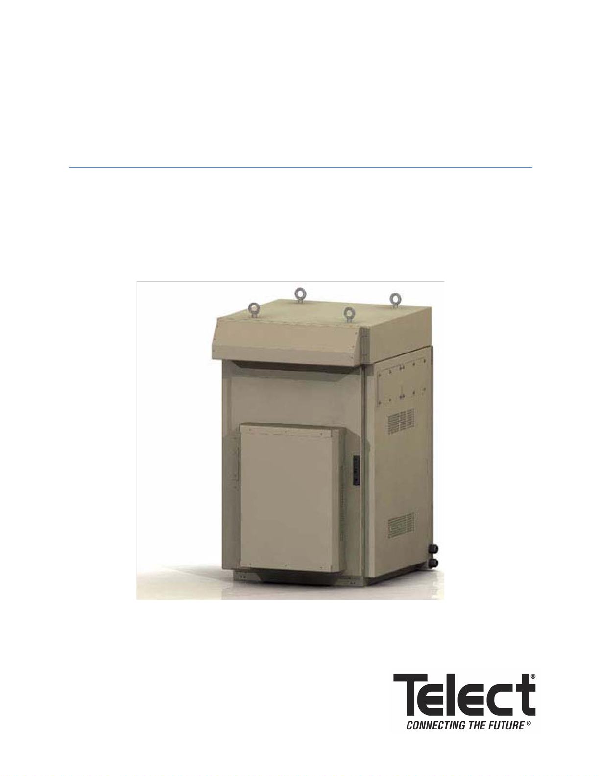
nrgSMART™ 2-compartment 24RU Enclosures:
IOE-24S-A203
Installation Guide

Page ii
Telect, Inc. • USA +1.509.926.6000 • Mexico +52.33.3836.37.52
www.telect.com • © 2011 Telect, Inc., All Rights Reserved, 139249-1 A0
nrgSMART™ 2-compartment 24RU Enclosure:
IOE-24S-A203
Installation Guide, Part Number 139249-1
© 2011, Telect, Inc., All Rights Reserved
Telect, nrgSMART, and Connecting the Future are registered trademarks of Telect, Inc.
Telect assumes no liability from the application or use of these products. Neither does Telect
convey any license under its patent rights nor the patent rights of others. This document and the
products described herein are subject to change without notice.
About Telect
Telect offers complete solutions for physical layer connectivity, power, equipment housing and
other network infrastructure equipment. From outside plant and central office to inside the home,
Telect draws on more than 25 years of experience to deliver leading edge product and service
solutions. Telect is committed to providing superior customer service and is capable of meeting
the dynamic demands of customer and industry requirements. This commitment to customer and
industry excellence has positioned Telect as a leading connectivity and power solution provider
for the global communications industry.
Technical Support
www.telect.com>support>technical assistance center or
http://www.telect.com/www/Support/TechnicalAssistanceCenter.aspx
(Make sure to have your login and password available. If you do not have a login and
password, contact your local market manager.)
Phone: 888-821-4856 (From 8:00 a.m. to 4:00 p.m. PT)
After hours, for critical, service-affecting calls ONLY, please have your equipment serial
numbers and date of manufacture available in order to process the call.)
Email: [email protected]

Page iii
Telect, Inc. • USA +1.509.926.6000 • Mexico +52.33.3836.37.52
www.telect.com • © 2011 Telect, Inc., All Rights Reserved, 139249-1 A0
nrgSMART™ 2-compartment 24RU Enclosures:
IOE-24S-A203
Installation Guide
Table of Contents
Chapter 1: Introduction ............................................................................................................. 1
1.1 Purpose ............................................................................................................................ 1
1.2 Audience .......................................................................................................................... 1
1.3 Standard Precautionary Messages ..................................................................................1
1.4 IMPORTANT INSTALLATION GUIDELINES .................................................................. 2
A. Rectifier Load Limits .............................................................................................. 2
B. Active Thermal Load Limits ................................................................................... 2
C. Circuit Review ........................................................................................................2
D. Grounding on the Front of the Enclosure .............................................................. 2
1.5 Tools and Equipment Required ....................................................................................... 3
1.5.1 Safety Equipment .................................................................................................... 3
1.5.2 Essential Tools........................................................................................................ 3
1.5.3 Recommended Tools .............................................................................................. 3
1.5.4 MDS Modules ..........................................................................................................3
1.6 Service............................................................................................................................. 4
1.6.1 Technical Support ................................................................................................... 4
1.6.2 In-Warranty Service ................................................................................................ 4
1.6.3 Out-Of-Warranty Service .........................................................................................4
1.6.4 Repacking for Shipment.......................................................................................... 4
1.7 Installation Flowchart ....................................................................................................... 5
Chapter 2: Setting up the Enclosure ........................................................................................ 7
2.1 Transporting and Storing the Enclosure ..........................................................................7
2.2 Inspecting the Shipment .................................................................................................. 7
2.3 Unpacking and Preparing for Mounting ...........................................................................8
2.4 Maneuvering the Enclosure .............................................................................................9
Chapter 3: Mounting Options for the Enclosure.................................................................... 11
3.1 Installing the Enclosure using a Concrete Installation Kit ..............................................11
3.2 Mounting the Enclosure to an Installed Plinth (Part #IOE-ACCS-003-G) ....................... 13
3.3 Reversing the Door Swing .............................................................................................14
Chapter 4: Installing the Cable Management Kits ................................................................ 21
4.1 Installing the Generic External Cable Management Kit (IOE-ACCS-006-G) ................. 21

Page iv
Telect, Inc. • USA +1.509.926.6000 • Mexico +52.33.3836.37.52
www.telect.com • © 2011 Telect, Inc., All Rights Reserved, 139249-1 A0
4.2 Installing the Nokia External Cable Management Kit (IOE-ACCS-005-G)..................... 23
Chapter 5: Connecting the AC Power.................................................................................... 29
5.1 Overview......................................................................................................................... 29
5.2 AC Service Connection .................................................................................................. 30
Chapter 6: Grounding the Enclosure ..................................................................................... 31
6.1 Grounding the Enclosure ............................................................................................... 31
Chapter 7: Installing the Batteries........................................................................................... 33
7.1 Overview........................................................................................................................ 33
7.2 Battery Installation ......................................................................................................... 34
7.3 Hydrogen Gas Ventilation Kit Installation (Optional) ...................................................... 37
7.3.1 Installing the Hydrogen Gas Ventilation Kit (Part # 305030) .................................38
Chapter 8: Connecting to Other Equipment .......................................................................... 43
8.1 Overview........................................................................................................................ 43
8.2 Connecting DC Power Cables ....................................................................................... 44
8.3 Alarm and Control ..........................................................................................................46
8.3.1 Connecting Alarm and Control Wiring to the I/O Board ........................................ 48
8.3.2 Ground Strap and Radio Verification .................................................................... 49
Chapter 9: Turning up the DC Power System....................................................................... 51
9.1 Turning up the DC Power System ................................................................................. 51
Chapter 10: Turning up the System ....................................................................................... 57
11.1 Alerts ............................................................................................................................ 57
11.2 Before You Turn on the System ................................................................................... 60
11.3 Turning up the Enclosure ............................................................................................. 61
11.4 Cable Sizes .................................................................................................................. 63
Chapter 11: Troubleshooting .................................................................................................. 65
12.1 Fan/air Flow Issues...................................................................................................... 65
12.2 DC Power System Issues ............................................................................................ 66
12.3 Grounding in the St. Louis Market Area ....................................................................... 75
12.4 Microwave Radio Power Feed Correction ...................................................................75
List of Figures
Figure 1 - Installation Flowchart ................................................................................................... 5
Figure 2 - T-Mobile Portal............................................................................................................. 8
Figure 3 - Lifting Measurements................................................................................................... 9
Figure 4 - Isolation Pad .............................................................................................................. 11
Figure 5 - Isolation and Anchor Stack ........................................................................................ 11
Figure 6 - Installing the Enclosure ............................................................................................. 12
Figure 7 - Plinth Assemby for Single-Bay Enclosure .................................................................13

Page v
Telect, Inc. • USA +1.509.926.6000 • Mexico +52.33.3836.37.52
www.telect.com • © 2011 Telect, Inc., All Rights Reserved, 139249-1 A0
Figure 8 - Windstay Bracket ....................................................................................................... 14
Figure 9 - Disconnecting the Ground Wire .................................................................................14
Figure 10 - Lifting Hinge Pin ...................................................................................................... 15
Figure 11 - Removing Door Hinges ........................................................................................... 16
Figure 12 - Removing Handle Cover Plate ................................................................................ 16
Figure 13 - Removing Rod Controller ........................................................................................ 17
Figure 14 - Handle Cover Plate Installation ............................................................................... 18
Figure 15 - Removing Roller Catches.........................................................................................18
Figure 16 - Back of Alarm Switch................................................................................................18
Figure 17 - Removing the Door Alarm Switch.............................................................................19
Figure 18 - Reinstalling Door Alarm Switch................................................................................ 19
Figure 19 - Pushing Hinge Pins .................................................................................................20
Figure 20 - Reinstalling Windstay Bracket .................................................................................20
Figure 21 - Removing the Covers .............................................................................................. 21
Figure 22 - Snapping in the Bottom Cover ................................................................................. 22
Figure 23 - Bottom Rail Cover ................................................................................................... 22
Figure 24 - Side Screws in Place ...............................................................................................23
Figure 25 - Attaching the Right Channel .................................................................................... 24
Figure 26 - Close-up of Brackets ...............................................................................................25
Figure 27 - Left Side Installation ................................................................................................ 25
Figure 28 - Brackets ................................................................................................................... 26
Figure 29 - Head ........................................................................................................................ 26
Figure 30 - Completed External Cable Management Kit for Nokia Installation .......................... 27
Figure 31 - Knockouts ................................................................................................................ 30
Figure 32 - AC Power Block ....................................................................................................... 30
Figure 33 - Lug Kit, Part #305670 ..............................................................................................31
Figure 34 - Grounding Points for Frame.................................................................................... 32
Figure 35 - Disconnect Breaker .................................................................................................34
Figure 36 - Spacing in the Battery Rack, Top View ................................................................... 35
Figure 37 - Installing the Retaining Bracket ...............................................................................35
Figure 38 - Connecting the Battery Cables ................................................................................36
Figure 39 - -48V Battery String Shown for Illustration ................................................................ 36
Figure 40 - Example of Completed Hydrogen Gas Ventilation Kit .............................................37
Figure 41 - Capping the Unused Vent Tubes ............................................................................39
Figure 42 - Inserting the First Tubes ..........................................................................................39
Figure 43 - Inserting Elbow and T-shaped Hoses ......................................................................40
Figure 44 - Connecting the T-hoses .......................................................................................... 40

Page vi
Telect, Inc. • USA +1.509.926.6000 • Mexico +52.33.3836.37.52
www.telect.com • © 2011 Telect, Inc., All Rights Reserved, 139249-1 A0
Figure 45 - Connecting Tubes ...................................................................................................40
Figure 46 - Knockout .................................................................................................................. 41
Figure 47 - Completed Hydrogen Gas Vent Kit .........................................................................41
Figure 48 - Cable Slot and Cord Grip ........................................................................................ 45
Figure 49 - DC Cable Openings .................................................................................................46
Figure 50 - Cables Looping Through to Front ............................................................................ 47
Figure 51 - DC Power System ...................................................................................................47
Figure 52 - DC Connections ...................................................................................................... 48
Figure 53 - I/O Board ................................................................................................................. 49
Figure 54 - Connecting the Wiring into the RJ45 Connectors on the I/O Board ........................ 50
Figure 55 - Connecting the Wiring into the Terminal Blocks...................................................... 50
Figure 56 - Matching the Rectifier Slots with their Breakers.......................................................53
Figure 57 - DC Power System ...................................................................................................54
Figure 58 - Rectifier Breakers Shown Turned OFF ...................................................................54
Figure 59 - Inserting the MDS Module ....................................................................................... 55
Figure 60 - Inside of MDS Slot.................................................................................................... 55
Figure 61 - Rear of MDS Module ............................................................................................... 55
Figure 62 - Inserting MDS Module ............................................................................................. 56
Figure 63 - I/O Distribution Board.............................................................................................. 57
Figure 64 - I/O Distribution Board Close-up ............................................................................... 57
Figure 65 - DC Power System ...................................................................................................62
Figure 66 - Battery Disconnect Breaker .....................................................................................63
Figure 67 - GFI ........................................................................................................................... 64
Figure 68 - Door Open Alarm Switch .........................................................................................64

Page 1
Telect, Inc. • USA +1.509.926.6000 • Mexico +52.33.3836.37.52
www.telect.com • © 2011 Telect, Inc., All Rights Reserved, 139249-1 A0
Chapter 1: Introduction
1.1 Purpose
This User Manual describes the installation procedures for the nrgSMART™ 2-compartment
IOE-24S-A203 enclosure and provides procedures for planning and installation.
1.2 Audience
This document provides information pertinent to installers.
1.3 Standard Precautionary Messages
This document contains the following precautionary messages:
DANGER
!
DANGER! indicates a situation that could cause death or severe personal injury
WARNING
!
WARNING! indicates a situation that could cause minor personal injury.
CAUTION
!
CAUTION! indicates a situation where the equipment could become damaged.
ALERT
!
ALERT! indicates a situation that could cause a problem with the operation of
the machinery.
Telect, Inc., is not responsible for any equipment damage or poor operating performance when
you do not follow these guidelines or when you use non-certified installers.
ALERT
!
ALERT! Only qualified technicians may install and maintain this product.
These instructions presume you have verified that the Telect equipment you are installing is
compatible with the rest of the system, including power, ground, circuit protection, signal
characteristics, equipment from other vendors, and local codes or ordinances.

Page 2
Telect, Inc. • USA +1.509.926.6000 • Mexico +52.33.3836.37.52
www.telect.com • © 2011 Telect, Inc., All Rights Reserved, 139249-1 A0
1.4 IMPORTANT INSTALLATION GUIDELINES
ALERT
!
ALERT! It is absolutely IMPERATIVE that you understand and follow these guidelines.
A. Rectifier Load Limits
The enclosure ships from the factory with three TRM-48M rectifiers (1800W @ 92%
efficiency), providing a system design load capacity of 75A with N+1 redundancy.
If you connect equipment such as 2G BTS units, etc., in addition to Node B and AAV
equipment, then it is possible to exceed this system design limit. In such scenarios, it is
necessary to use TRM-48ES high efficiency rectifiers (2000W @ 96% efficiency). In such a
case, you MUST replace the existing TRM-48M rectifiers with TRM-48ES rectifiers and add
the appropriate number of additional TRM-48ES rectifiers up to the new system load design
of 160A plus N+1 redundancy.
B. Active Thermal Load Limits
Whenever you plan the 6RU equipment zone below the divider panel, you must consider the
following: When you install equipment you must adhere to the compartment’s thermal load
limits. The estimated* thermal budget associated with the installation of ancillary equipment
in this enclosure is 100W MAX, based on 38oC ambient and 40oC internal temperature.
*Telect MUST review the actual equipment configuration to confirm the thermal acceptability
of the equipment that you intend to install in this zone.
Consider your thermal budget and the manufacturer’s equipment requirements. Install
the equipment in an environment compatible with the maximum temperature specified by
the manufacturer.
Air flow: For safe operation of the equipment in the 6RU zone, make sure that the
installed equipment conforms to the manufacturer’s equipment requirements for air flow.
C. Circuit Review
Determine the number of MDS modules required for installation and order the appropriate
number of MDS modules. Also be sure to buy the appropriate breaker sizes associated with
your circuit requirements. See Section “1.5.4 MDS Modules” on page 3 for details.
D. Grounding on the Front of the Enclosure
When you attach the ground ring to the enclosure frame, it is CRITICAL that you thoroughly
coat any exposed metal with No-Ox compound. See “Grounding the Enclosure” on
page 31.

Page 3
Telect, Inc. • USA +1.509.926.6000 • Mexico +52.33.3836.37.52
www.telect.com • © 2011 Telect, Inc., All Rights Reserved, 139249-1 A0
1.5 Tools and Equipment Required
Installers should have the following tools and equipment available for this installation:
1.5.1 Safety Equipment
Use approved safety equipment as required by local health and safety regulations including (but
not restricted to)
• Safety glasses
• Safety gloves
• Safety footwear
• Appropriate handling equipment for batteries and other heavy items
• Appropriate platform(s) and access for working at height (if required)
1.5.2 Essential Tools
Standard electrical toolkit with insulated tools, plus
• Standard and insulated hand tools
• Cable crimping tool and crimp lugs suitable for all cable sizes and connectors used
• Torque wrench with pivot head and insulated handle
• Heat-shrink tubing and heat gun
• Digital multimeter
• Non-static clothing
1.5.3 Recommended Tools
Additional recommended tools include
• Drill for cement
• Vacuum or broom
• Laptop with
−USB port (for use with SC200)
−Test load (to suit maximum output of DC power system)
−Labeling tool and labels
−Clamp-on ammeter
1.5.4 MDS Modules
The MDS modules are uniquely designed for circuit breakers and GMT circuits. Installers can
configure MDS modules as necessary for a given site:

Page 4
Telect, Inc. • USA +1.509.926.6000 • Mexico +52.33.3836.37.52
www.telect.com • © 2011 Telect, Inc., All Rights Reserved, 139249-1 A0
• 10-Circuit, 15A GMT Fuse Module, Model #MDS-GMTM-10x15A Installation Guide
(p/n 138654)
• Dual Circuit Breaker Module, Model #MDS-DCBM-SP100 Installation Guide (p/n 138646)
1.6 Service
1.6.1 Technical Support
If you encounter technical difficulties, please use the online request form at www.telect.com
under Support\Technical Support or call Telect directly at 888.821.4856 (8:00 a.m. to 4:00 p.m.
PT). After hours, for critical, service-affecting calls ONLY, please have your equipment serial
numbers and date of manufacture available in order to process the call.)
You may also contact us at www.telect.com>support>technical assistance center or
http://www.telect.com/www/Support/TechnicalAssistanceCenter.aspx
Email: [email protected]m
1.6.2 In-Warranty Service
ship a new replacement product, along with a return shipping label and authorization information.
When you receive your replacement product, pack up the defective product and return it to Telect
using the return label, box, and any additional information provided.
1.6.3 Out-Of-Warranty Service
Follow the In-Warranty directions above. Telect charges a processing fee for out-of-warranty
service, and you must submit a Purchase Order along with a Return Material Authorization
(RMA) before returning equipment. The processing fee guarantees a repair estimate and is
credited against actual material and labor costs. Call Telect's quality call center at 877.471.7245
for more information.
1.6.4 Repacking for Shipment
1. Tag the equipment showing owner’s name, address, and telephone number, together with a
detailed description of the problem.
2. Use the original shipping container if possible. If you do not have it, package the equipment in
a way to prevent shipping damage. Include the RMA inside the container and legibly print the
RMA number on the outside of the package, near the shipping address.
3. Insure the package.

Page 5
Telect, Inc. • USA +1.509.926.6000 • Mexico +52.33.3836.37.52
www.telect.com • © 2011 Telect, Inc., All Rights Reserved, 139249-1 A0
1.7 Installation Flowchart
The following flowchart demonstrates the order of procedures that you should follow to properly
install this enclosure.
Figure 1 - Installation Flowchart
Installing the enclosure
All materials
present and
in working
order?
Yes
No Notify carrier
and Telect’s
service department
Installing the batteries
Transporting, storing, unpacking
and inspecting the enclosure
End
Maneuvering the enclosure
Mounting the enclosure
Connecting the AC power
Grounding the enclosure
Connecting to
Turning up the site
other equipment
Installing the
DC power system
Installing the optional cable
management accessories

Page 6
Telect, Inc. • USA +1.509.926.6000 • Mexico +52.33.3836.37.52
www.telect.com • © 2011 Telect, Inc., All Rights Reserved, 139249-1 A0
This page intentionally left blank.

Page 7
Telect, Inc. • USA +1.509.926.6000 • Mexico +52.33.3836.37.52
www.telect.com • © 2011 Telect, Inc., All Rights Reserved, 139249-1 A0
Chapter 2: Setting up the Enclosure
2.1 Transporting and Storing the Enclosure
WARNING
!
WARNING! DO NOT transport the enclosure with batteries installed. Install batteries only
after the enclosure is transported to the site and secured to the pad. Transporting the unit
with batteries installed may cause a short circuit, fire, explosion, and/or damage to the en-
closure and installed equipment.
The enclosure is shipped on a wooden pallet. Do not remove the enclosure and other packing
materials from the pallet until the enclosure has been transported to the installation site. Always
ship and store the enclosure in an upright position on the pallet.
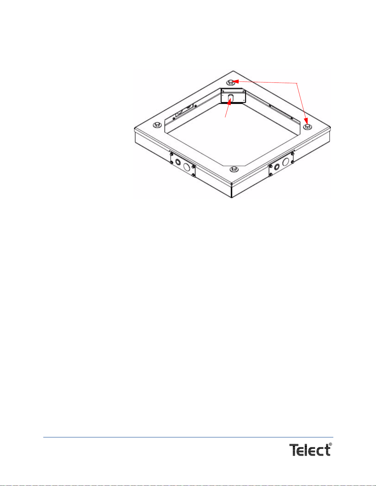
A standard enclosure consists of a frame with a top panel and four lifting eyebolts, solar side
panels, front door, and rear hatch.
2.2 Inspecting the Shipment
Please read these instructions carefully before beginning installation. If you need assistance, call
Technical Support at 1.888.821.4856 (domestic calls), or 509.921.6161 (Option 2), or email us at
Inspect equipment after unpacking and compare it to the packing list.
Immediately report any shipping damage, defects, or missing parts to Telect at 1.800.551.4567.
Keep all documentation that comes with your shipment.
Telect is not liable for shipping damage. If the product is damaged, notify the carrier and call
Telect’s Customer Service Department at 1.800.551.4567 (domestic only) or 1.509.926.6000 for
further recourse.
NOTE: For service or warranty information, please visit the telect.com website, or email inquiries
to getinfo@Telect.com and click on the “Support” tab, or phone us at 800.551.4567 (domestic
only) or 509.926.6000.
Keep the container until you have checked equipment operation. If you experience any kind of
problem, call Telect's Customer Service Department at 1.800.551.4567 or 1.509.926.6000. Use
the original, undamaged container if you are instructed to return the enclosure to Telect.
Make sure the following equipment is available in your enclosure:
• 1 Dual-breaker MDS module (Breakers are not included and must be ordered separately.)
• 3 Rectifiers (part # TRM-48M)
• 1 Telect Exterior ground lug kit (part #305670)
• 1 Installation Kit (part # 304485)
• 1 Telect Hydrogen gas ventilation kit (part #305030) (optional)
Page 8
Telect, Inc. • USA +1.509.926.6000 • Mexico +52.33.3836.37.52
www.telect.com • © 2011 Telect, Inc., All Rights Reserved, 139249-1 A0
• 1 Allen wrench
• GMT Fuse Kit (part # 305756)
• Documentation (in addition to this installation guide):
−MDS Dual Circuit Breaker Module, Model #MDS-DCBM-SP100 Installation Guide
−MDS 10-Circuit, 15A GMT Fuse Module, Model #MDS-GMTM-10x15A Installation Guide
−Eaton Certificate of Conformity, Product: IOBGP-00
−Eaton Certificate of Conformity, Product: SC200-00
−McLean Warranty Card (Yellow)
−McLean Instruction Manual
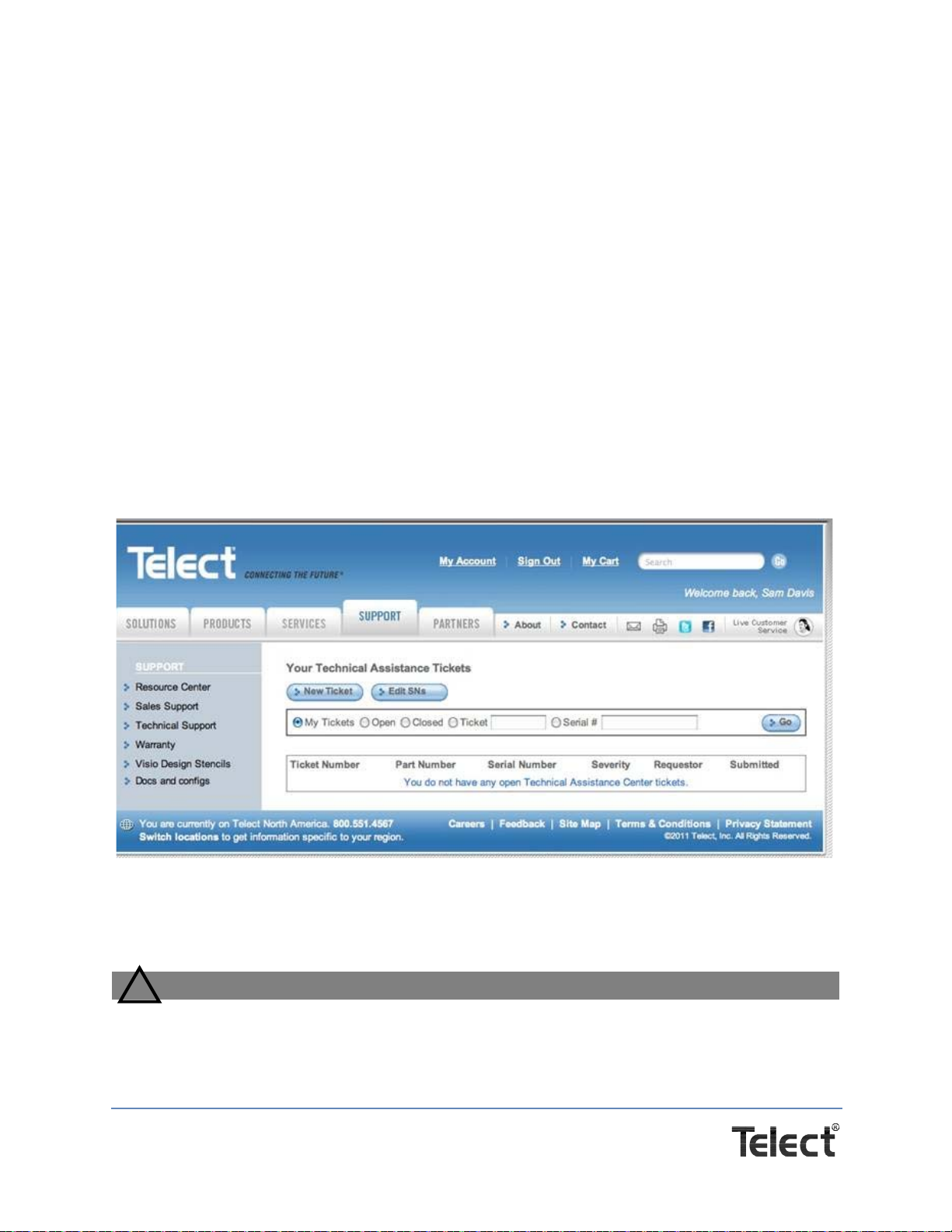
To find additional documents,
1. Go to http://www.telect.com/www/Support/TechnicalAssistanceCenter.aspx.
2. At the Telect screen shown in Figure 2, go to Docs and configs on the left-hand side.
3. Find the finished goods part number you are looking for in the table that appears, then find
the link to the document you need.
2.3 Unpacking and Preparing for Mounting
WARNING
!
WARNING! Install the enclosure BEFORE installing any batteries. See “Installing the bat-
teries” on page 35 for the procedure to install the batteries.
Figure 2 - T-Mobile Portal
Page 9
Telect, Inc. • USA +1.509.926.6000 • Mexico +52.33.3836.37.52
www.telect.com • © 2011 Telect, Inc., All Rights Reserved, 139249-1 A0
Remove the packaging materials around the enclosure, but leave the enclosure on the
shipping pallet. NOTE: If the cabinet is pre-mounted to an optional plinth, unbolt the plinth from
the pallet and store the mounting hardware close by in a safe place.
ALERT
!
ALERT! Do not lift the enclosure with the batteries installed.
Make sure you have figured the combined weight of everything you are lifting (~600 pounds for
the enclosure as configured by Telect plus any additional, customer-installed, auxiliary
equipment) before performing the lift. A site installation engineer should verify that you have
adequate support before you lift anything.
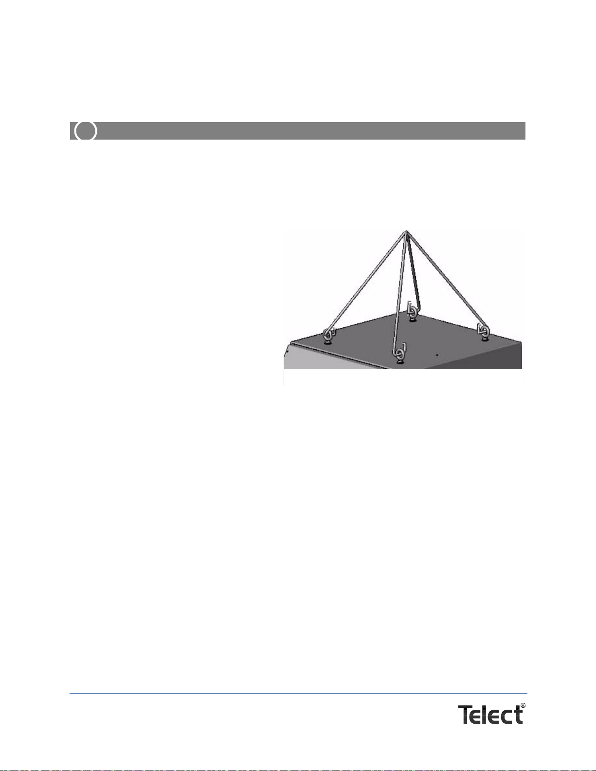
2.4 Maneuvering the Enclosure
Procedure steps:
1. Attach lifting equipment to the eye bolts.
2. Lift the enclosure with hoist system.
Make sure the straps are equal in length
to balance the load, a minimum of 24" to
minimize the lateral load on the eye-
bolts, as shown in Figure 3.
3. After the enclosure is in place, remove
the eye bolts and replace them with the
enclosed bolts as soon as the enclosure is secured.
This procedure is complete.
24”minimum
24” minimum
Figure 3 - Lifting Measurements

Page 10
Telect, Inc. • USA +1.509.926.6000 • Mexico +52.33.3836.37.52
www.telect.com • © 2011 Telect, Inc., All Rights Reserved, 139249-1 A0
This page intentionally left blank.

Page 11
Telect, Inc. • USA +1.509.926.6000 • Mexico +52.33.3836.37.52
www.telect.com • © 2011 Telect, Inc., All Rights Reserved, 139249-1 A0
Chapter 3: Mounting Options for
the Enclosure
Use one of the following pad-mount procedures to mount your enclosure. Local operators
provide platform mount details before installation.
Whether you are mounting the enclosure directly to concrete, to a plinth, or mounting the
enclosure/plinth combination directly to concrete, in most cases, you will need to install concrete
anchors. Use the anchors appropriate to your needs. The following general installation
instructions apply or you can use the anchor manufacturer’s installation instructions. Make sure
you have the mounting kit that includes the isolation pad and hardware.
3.1 Installing the Enclosure using a
Concrete Installation Kit
Every enclosure ships with a Concrete Installation Kit,
which contains
• an isolation pad
• four M12 Seismic anchors
• four each .030, .060, .120, .250 shims
• four shoulder washers
• four 2 x 2 x 1/44 (.812 hole) anchor plates
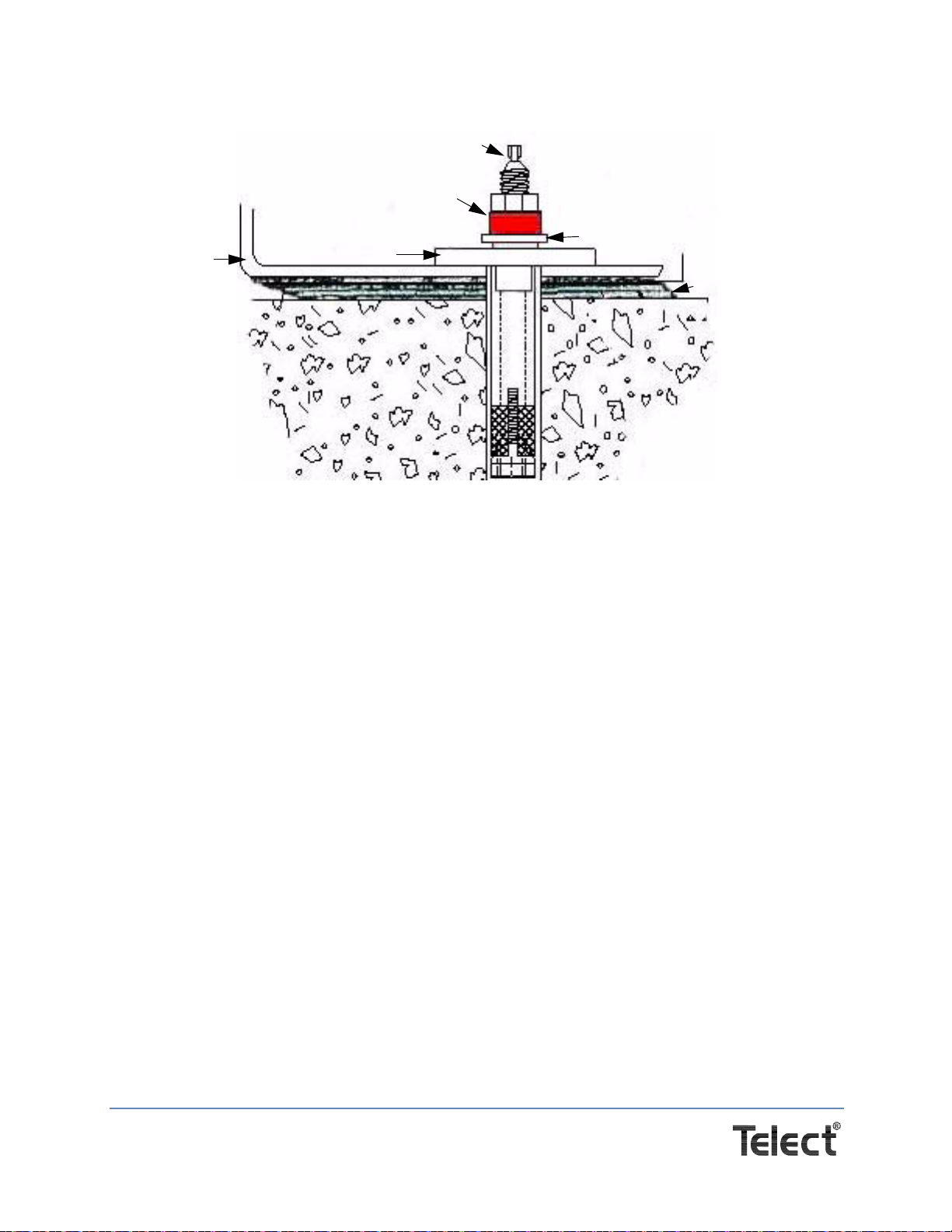
Procedure steps:
1. Install the anchors per normal industry standards.
2. Place the isolation pad over the anchor bolts.
3. Check that the pad is level and doesn't rock on the slab. If it rocks, insert shims between the
pad and the ground to eliminate any enclosure movement. See Figure 5.
Figure 4 - Isolation Pad
Isolation pad
Figure 5 - Isolation and Anchor Stack
Shims, as needed
M12 Seismic Anchor
Anchor Plate
Shoulder Washer
Page 12
Telect, Inc. • USA +1.509.926.6000 • Mexico +52.33.3836.37.52
www.telect.com • © 2011 Telect, Inc., All Rights Reserved, 139249-1 A0
4. Lift and position the enclosure over the anchor bolts.
5. Place the threaded studs through the holes in the base of the enclosure and thread them into
the anchor bolts until they are fully engaged in the threads of the bottom cones.
6. Tighten the studs.
7. Install the anchor plates and then thread the torque nut onto the stud.
8. Tighten the torque nut until it shears off the plastic-encased holding nut. At the shear point,
the holding nut will be properly torqued.
9. Place the shoulder washer over the anchor and make sure it is firmly seated to prevent the
mounting hardware from contacting the enclosure’s sheet metal.
10. Make sure that the door opens and closes properly.
This procedure is complete.
Enclosure
Stud
Torque nut
Shoulder washer
Isolation pad
Anchor Plate
Figure 6 - Installing the Enclosure
Page 13
Telect, Inc. • USA +1.509.926.6000 • Mexico +52.33.3836.37.52
www.telect.com • © 2011 Telect, Inc., All Rights Reserved, 139249-1 A0
3.2 Mounting the Enclosure to an Installed Plinth
(Part #IOE-ACCS-003-G)
When you install a plinth,
secure it to the concrete pad
first and then bolt the
enclosure to the plinth as
follows. Instructions for
installing the plinth to the
concrete pad are enclosed
in the plinth kit. For plinth
installation, use kit #I0E-
ACCS-003-G(305255).This
kit comes with the 4” tall
plinth, four bolts, four flat
and four split lockwashers.
Procedure steps:
1. Install the anchors as
describedinSection“3.1
Installing the Enclosure using a Concrete Installation Kit” on page 11 or as described in the
manufacturer’s instructions.
2. Place the isolation pad over the anchors, making sure that each of the anchors are centered
in the pad’s holes.
3. Position the plinth squarely over the holes in the isolation pad. Make sure that no part of the
plinth touches the anchors.
4. Place the plastic cover and square washer over the anchor’s metal sleeve in the hole. The
plastic flange should be on top of the square washer.
5. Insert the threaded studs.
6. Install the flat washers and the torque nuts onto the studs. Use a 3/8-in. socket wrench to
tighten the studs.
7. Using an open-ended wrench, tighten each torque nut until the head shears off. Repeat for all
four corners.
8. Check that the plinth is level and doesn't rock on the slab. Insert shims between the pad and
the plinth to eliminate any plinth movement.
9. Lift and position the enclosure over the plinth.
10. Carefully lower the enclosure onto the plinth.
11. Secure the enclosure to the plinth.
12. Make sure that the door opens and closes properly.
This procedure is complete.
4” tall
Anchor hole
Bolts with
washers
Figure 7 - Plinth Assemby for Single-Bay Enclosure

Page 14
Telect, Inc. • USA +1.509.926.6000 • Mexico +52.33.3836.37.52
www.telect.com • © 2011 Telect, Inc., All Rights Reserved, 139249-1 A0
3.3 Reversing the Door Swing
Procedure steps:
1. Open the door.
2. Unplug any wires connected
to the door.
3. On Bay 1 or the single bay’s front
door, unplug the wire harness from
the heat exchanger.
4. Disconnect the windstay bracket at
the bottom, inside corner of the en-
closure by using a 7/16” socket to
remove the two 1/4-20 Keps nuts
(circled in Figure 8) and flatwashers
from the bracket. Set the hardware
aside for reuse.
5. Disconnect the door’s ground wire
from the frame. Follow the ground wire to the frame
connection point. Use a 7/16” socket to remove the
1/4-20 keps nut. Set the hardware aside for reuse.
6. Locate the hinges and hinge pins on the left side.
Figure 8 - Windstay Bracket
Figure 9 -
Disconnecting the Ground Wire
Ground wire
Hinge & Pin
Table of contents
Other Telect Enclosure manuals

Popular Enclosure manuals by other brands

Moeller
Moeller M22-I Series installation instructions

Fender
Fender Bassman 115 operating instructions

Wet Sounds
Wet Sounds Stealth AS Series Installation & owner's manual

StarTech.com
StarTech.com SAT3510U2V instruction manual

Rittal
Rittal CS Toptec Assembly instructions

Dell
Dell PowerVault MD3000 Information update

Dynacord
Dynacord D 12A Architects and engineers specifications

Supermicro
Supermicro SC417BE1C-R1K23JBOD user manual

2E
2E GAMING VIRTUS NEO WHITE Operation guide

StarTech.com
StarTech.com SM21BMU31C3 user manual

Rittal
Rittal TS IT Pro Assembly and operating instructions

Rockford Fosgate
Rockford Fosgate RFYXZ-FSE manual


