TELEDYNE API Everywhereyoulook 480H User manual

User Manual
Model 480H
OZONE MONITOR
©Teledyne API (TAPI)
9970 Carroll Canyon Road
San Diego, CA 92131-1106
Toll-Free:
+1 800-324-5190
Phone:
+1 858-657-9800
Fax:
+1 858-657-9816
Email:
api-sales@teledyne.com
Website:
http://www.teledyne-api.com
Copyright 2021 09421A DCN8343
Teledyne API 30 June 2021

E IS INTENTIONALLY LEFT BLANK
09421A DCN8343 Teledyne API Model 480H O3Monitor User Manual i
SAFETY MESSAGES
Important safety messages are provided throughout this manual for the purpose of
avoiding personal injury or instrument damage. Please read these messages
carefully. Each safety message is associated with a safety alert symbol and placed
throughout this manual and inside the instrument. The symbols with messages are
defined as follows:
WARNING: Electrical Shock Hazard
HAZARD: Strong oxidizer
GENERAL WARNING/CAUTION: Read the accompanying message
for specific information.
CAUTION: Hot Surface Warning
Do Not Touch: Touching some parts of the instrument without
protection or proper tools could result in damage to the part(s) and/or the
instrument.
Technician Symbol: All operations marked with this symbol are to be
performed by qualified maintenance personnel only.
Electrical Ground: This symbol inside the instrument marks the central
safety grounding point for the instrument.
CAUTION
This product should only be used for the purpose and in the manner
described in this manual. If you use this product in a manner other
than that for which it was intended, unpredictable behavior could
ensue with possible hazardous consequences.
NEVER use any combustible/explosive gas with this product!
ii Teledyne API Model 480H O3Monitor User Manual 09421A DCN8343
CONSIGNES DE SÉCURITÉ
Des consignes de sécurité importantes sont fournies tout au long du présent manuel
dans le but d’éviter des blessures corporelles ou d’endommager les instruments.
Veuillez lire attentivement ces consignes. Chaque consigne de sécurité est
représentée par un pictogramme d’alerte de sécurité; ces pictogrammes se
retrouvent dans ce manuel et à l’intérieur des instruments. Les symboles
correspondent aux consignes suivantes:
AVERTISSEMENT: Risque de choc électrique
DANGER: Oxydant puissant
AVERTISSEMENT GÉNÉRAL / MISE EN GARDE: Lire la consigne
complémentaire pour des renseignements spécifiques
MISE EN GARDE: Surface chaude
Ne pas toucher: Toucher à certaines parties de l’instrument sans protection
ou sans les outils appropriés pourrait entraîner des dommages aux pièces ou
à l’instrument.
Pictogramme « technicien »: Toutes les opérations portant ce symbole
doivent être effectuées uniquement par du personnel de maintenance
qualifié.
Mise à la terre: Ce symbole à l’intérieur de l’instrument détermine le point
central de la mise à la terre sécuritaire de l’instrument.
MISE EN GARDE
Cet produit doit être utilisé aux fins décrites et de la manière décrite
dans ce manuel. Si vous utilisez cet produit d’une autre manière que
celle pour laquelle il a été prévu, l’instrument pourrait se comporter de
façon imprévisible et entraîner des conséquences dangereuses.
NE JAMAIS utiliser de gaz explosive ou combustible avec cet produit!

09421A DCN8343 Teledyne API Model 480H O3Monitor User Manual iii
WARRANTY
WARRANTY POLICY (02024J)
Teledyne API (TAPI), a business unit of Teledyne Instruments, Inc., provides that:
Prior to shipment, TAPI equipment is thoroughly inspected and tested. Should
equipment failure occur, TAPI assures its customers that prompt service and support
will be available. (For the instrument-specific warranty period, please refer to the
“Limited Warranty” section in the Terms and Conditions of Sale on our website at
the following link: http://www.teledyne-api.com/terms_and_conditions.asp).
COVERAGE
After the warranty period and throughout the equipment lifetime, TAPI stands ready
to provide on-site or in-plant service at reasonable rates similar to those of other
manufacturers in the industry. All maintenance and the first level of field
troubleshooting are to be performed by the customer.
NON-TAPI MANUFACTURED EQUIPMENT
Equipment provided but not manufactured by TAPI is warranted and will be
repaired to the extent and according to the current terms and conditions of the
respective equipment manufacturer’s warranty.
Product Return
All units or components returned to Teledyne API should be properly packed for
handling and returned freight prepaid to the nearest designated Service Center. After
the repair, the equipment will be returned, freight prepaid.
The complete Terms and Conditions of Sale can be reviewed at
http://www.teledyne-api.com/terms_and_conditions.asp
CAUTION – Avoid Warranty Invalidation
Failure to comply with proper anti
-Electro-Static Discharge (ESD)
handling and packing instru
ctions and Retu
rn Merchandise
Authorization (RMA) procedures when returning parts for repair or
calibration may void your warranty. For anti
-ESD handling and
packi
ng instructions please refer to the manual, Fundamentals of
ESD, PN 04786, in its
“Packing Components for Return to Teledyne
API’s Customer Service”
section. The manual can be downloaded
from our website at
http://www.teledyne-api.com. RMA procedures
can also be found on our website
.

iv Teledyne API Model 480H O3Monitor User Manual 09421A DCN8343
This page intentionally left blank

09421A DCN8343 Teledyne API Model 480H O3Monitor User Manual v
TABLE OF CONTENTS
1. INTRODUCTION..........................................................................................................9
2. SPECIFICATIONS AND AGENCY APPROVALS ................................................11
2.1. MODEL 480H SPECIFICATIONS ..........................................................................................................11
2.2. APPROVALS .......................................................................................................................................12
2.2.1. Safety...........................................................................................................................................12
2.2.2. EMC ............................................................................................................................................12
2.2.3. Other Type Certifications............................................................................................................12
3. GETTING STARTED.................................................................................................13
3.1. UNPACKING .......................................................................................................................................14
3.2. MECHANICAL INSTALLATION ............................................................................................................14
3.3. AC POWER CONNECTION...................................................................................................................16
3.3.1. Wiring Requirements...................................................................................................................16
3.3.2. Wiring Instructions .....................................................................................................................17
3.4. ELECTRICAL I/O CONNECTIONS.........................................................................................................18
3.4.1. Analog Output.............................................................................................................................19
3.4.2. Status Outputs .............................................................................................................................21
3.4.3. Hi-Current Relay Outputs ...........................................................................................................22
3.4.4. Failsafe Operation Signal and Relay outputs .............................................................................22
3.4.5. Digital Communication Interfaces..............................................................................................23
3.5. PNEUMATIC CONNECTIONS................................................................................................................24
3.5.1. Installing Flow Control Assemblies ............................................................................................24
3.5.2. Ozone Inlet Connection...............................................................................................................24
3.5.3. Zero Gas Inlet Connection ..........................................................................................................25
3.5.4. Exhaust Connection ....................................................................................................................25
3.6. PNEUMATIC FLOW DIAGRAM.............................................................................................................25
4. CALIBRATION...........................................................................................................26
4.1. FACTORY CALIBRATION ....................................................................................................................26
4.2. ZERO,SPAN,AND FLOW CALIBRATIONS ............................................................................................26
5. OPERATION ...............................................................................................................27
5.1. FRONT PANEL OVERVIEW ..................................................................................................................27
5.1.1. Display ........................................................................................................................................27
5.1.2. Control Keys ...............................................................................................................................28
5.1.3. Indicator LEDs............................................................................................................................28
5.2. FRONT PANEL MENUS........................................................................................................................29
5.2.1. Editing Settings ...........................................................................................................................29
5.2.2. Sensor Menu................................................................................................................................30
5.2.3. Diag Menu ..................................................................................................................................30
5.2.4. Setup Menu..................................................................................................................................32
5.2.5. Status Screen...............................................................................................................................35
6. DIGITAL COMMUNICATIONS..............................................................................36
6.1. ETHERNET CONFIGURATION ..............................................................................................................36
6.2. SERIAL CONFIGURATION -RS-232 AND RS-485................................................................................37
6.3. MODBUS REGISTER MAPS...............................................................................................................39
6.3.1. MODBUS Commands Supported................................................................................................39
6.3.2. Notes on MODBUS registers ......................................................................................................39
6.3.3. Real-Time Concentration and Status Registers (Read Only) ......................................................40
6.3.4. Instrument Setup and Configuration Registers (Read / Write)....................................................40

vi Teledyne API Model 480H O3Monitor User Manual 09421A DCN8343
7. MAINTENANCE.........................................................................................................42
7.1. MAINTENANCE SCHEDULE.................................................................................................................42
7.2. INSTRUMENT LAYOUT .......................................................................................................................43
7.3. PARTICULATE FILTER REPLACEMENT ................................................................................................44
7.4. AUTO-ZERO VALVE REPLACEMENT ..................................................................................................45
7.5. UV LED REPLACEMENT....................................................................................................................46
7.6. SENSOR MODULE REPLACEMENT ......................................................................................................47
7.7. DISPLAY ASSEMBLY REPLACEMENT..................................................................................................48
7.8. CLEANING EXTERIOR SURFACES OF THE 480H ..................................................................................49
8. TROUBLESHOOTING ..............................................................................................50
8.1.REFERENCE DRAWINGS .....................................................................................................................50
8.2. TROUBLESHOOTING USING FRONT PANEL STATUS LED AND STATUS OUTPUTS...............................50
8.2.1. Sensor OK ...................................................................................................................................52
8.2.2. Invalid Reading...........................................................................................................................52
8.2.3. Check Lamp.................................................................................................................................52
8.2.4. Pneumatic Error .........................................................................................................................52
8.2.5. Technical Assistance ...................................................................................................................53
9. PRINCIPLES OF OPERATION................................................................................54

09421A DCN8343 Teledyne API Model 480H O3Monitor User Manual vii
FIGURES
Figure 3-1. Model 480H Display and Control Panel .....................................................................................13
Figure 3-2. 480H Dimensions........................................................................................................................16
Figure 3-3. AC Power Connection to Monitor ..............................................................................................17
Figure 3-4. Interior Location of I/O Connectors............................................................................................19
Figure 3-5. Mainboard – Analog Output Configuration................................................................................21
Figure 3-6. Pneumatic Connections...............................................................................................................24
Figure 3-7. Pneumatic Diagram.....................................................................................................................25
Figure 5-1. Front Panel Display and Controls ........................................................................................27
Figure 5-2. Front Panel Selection and Control Buttons.........................................................................28
Figure 6-1. RS-232 Signal Configurations ....................................................................................................38
Figure 7-1. Instrument Layout.......................................................................................................................43
Figure 7-2. Particulate Filter (PN 02832) Replacement ................................................................................44
Figure 7-3. O3 Sensor Module Board............................................................................................................46
Figure 7-4. UV LED Access..........................................................................................................................46
Figure 7-5. Sensor Module Removal.............................................................................................................47
Figure 7-6. Display Assembly Removal........................................................................................................49
Figure 8-1. Display and Control Panel ..........................................................................................................50
Figure 8-2. Status Outputs .............................................................................................................................51

viii Teledyne API Model 480H O3Monitor User Manual 09421A DCN8343
TABLES
Table 3-1. Status Output Definitions .............................................................................................................22
Table 5-2. Sensor Menu Parameters ..............................................................................................................30
Table 5-3. Analog Step Test Values ..............................................................................................................30
Table 5-4. VARS List ....................................................................................................................................32
Table 5-5. Alarm Configuration Settings ......................................................................................................34
Table 6-1. RS-232/RS-485 Port Setup...........................................................................................................37
Table 7-1. Maintenance Schedule..................................................................................................................42
Table 8-1. Status LED/Output Definitions ....................................................................................................51

09421A DCN8343 Teledyne API Model 480H O3Monitor User Manual 9
1. INTRODUCTION
Teledyne API’s Model 480H Ozone Monitor measures high concentration ozone
monitor that measures process ozone concentrations and is specifically optimized
for applications in water treatment and in the medical, food, and beverage
industries. This microprocessor-controlled instrument provides fast response times
with minimal zero drift for accurate and stable readings, and it has built-in tests and
diagnostics to allow maximum uptime.
We at Teledyne API will be pleased to provide you with any support required so
that you may utilize our equipment to the fullest extent. Our full time technical
support department is always available to answer your questions.
Teledyne API, Technical Support,
9970 Carroll Canyon Road
San Diego, California 92131-1106 USA
Toll-free: +1 800-324-5190
Phone:
+1 858-657-9800
Fax: +1 858-657-9816
Email:
api-techsupport@teledyne.com
Website: http://www.teledyne-api.com

10 Teledyne API Model 480H O3Monitor User Manual 09421A DCN8343
This page intentionally left blank

09421A DCN8343 Teledyne API Model 480H O3Monitor User Manual 11
2. SPECIFICATIONS AND AGENCY APPROVALS
2.1. MODEL 480H SPECIFICATIONS
PARAMETER SPECIFICATION
M
easuring Principle UV absorption (Beer Lambert Law)
Ranges
0-5 WT% to 0-25 WT%
0-100 g/Nm3 to 0-400 g/Nm3
Measurement U
nits WT%, g/Nm3
Accuracy
±1% of Full Scale
Precision/Repeatabil
ity ±0.5% of Full Scale
Display Resolution
0.01 WT%, 0.1 g/Nm3
Response Time (
95%) <30 seconds to 95%
Com
pensation Pressure, Temperature
(NTP = 273.15K, 760 mmHg)
Gas Inlet Pressure Range
3.0-30.0 psig
Sample Flow Rate
0.2-2.0 LPM
Humidity Range
10-90% RH, non-condensing
Temper
ature Range 5-45o C
Dime
nsions (H x W x D)
NEMA 4X – 17.35” x 15.96” x 6.80”
(440.7 mm x 405.4 mm x 172.7 mm)
Weight
NEMA 4X – 17.6 lbs (8 kg)
Power
100-240 V~, 47-63 Hz, 74 W
E
nvironmental
Installation Category II
Pollution Degree 2
For Indoor/Outdoor Use
Maximum Operating Altitude 2000 meters
De
gree of Protection
(NEMA en
closure) IP65 (NEMA 4X)
Anal
og Output 0 – 5 V or 4-20 mA isolated output
Status Outputs
Sensor OK, Invalid Reading, Check Lamp, Pneumatic Error
High Current Relay Outputs
SPDT (Form C) Dry Contact, 250VAC, 5A
(System OK, Global HI alarm, Global HI-HI alarm)
Communication Int
erface Ethernet
RS-232/RS-485

12 Teledyne API Model 480H O3Monitor User Manual 09421A DCN8343
2.2. APPROVALS
This section presents Safety and Electromagnetic Compatibility (EMC) compliance
approvals for the Model 480H monitor.
2.2.1. SAFETY
IEC/EN 61010-1:2010 (3rd Edition), Safety requirements for electrical equipment
for measurement, control, and laboratory use.
2.2.2. EMC
IEC/EN 61326-1:2010, Class A Emissions/Industrial Immunity
FCC 47 CFR Part 15B, Class A Emissions
2.2.3. OTHER TYPE CERTIFICATIONS
For additional certifications, please contact Technical Support:
Toll-free: +1 800-324-5190
Phone: +1 858-657-9800
Fax: +1 858-657-9816
Email: api-techsupport@teledyne.com

09421A DCN8343 Teledyne API Model 480H O3Monitor User Manual 13
3. GETTING STARTED
WARNING – RISK OF DEATH OR SERIOUS INJURY!
To reduce the risk of death or serious injury from a
chemical/combustion explosion hazard due to flammable
gases/vapors/liquids, never allow contaminants to enter monitor
during installation or use. The combination of ozone and the catalytic
ozone destruct media in the monitor can produce strong oxidation
reactions. Never allow organic contaminants, including but not limited
to peroxides and chlorates, into monitor.
Figure 3-1. Model 480H Display and Control Panel

14 Teledyne API Model 480H O3Monitor User Manual 09421A DCN8343
3.1. UNPACKING
Upon receiving the 480H please verify that there is no apparent shipping damage.
(If damage has occurred please advise shipper first, then Teledyne API).
Check your packing slip for options that may be included, depending on your order,
e.g., disposable sample inlet filters.
3.2. MECHANICAL INSTALLATION
When installing the monitor be sure to leave sufficient clearance on sides, top, and
bottom for adequate ventilation and for access to make/adjust all connections. The
monitor must be mounted securely with four (4) bolts or anchors to a vertical
structure or wall capable of supporting 80 lbs. The mounting bolts or anchors must
be capable of supporting 20 lbs each. If using wall anchors, they must be suitable
for the type of wall construction and installed per the manufacturer’s specifications.
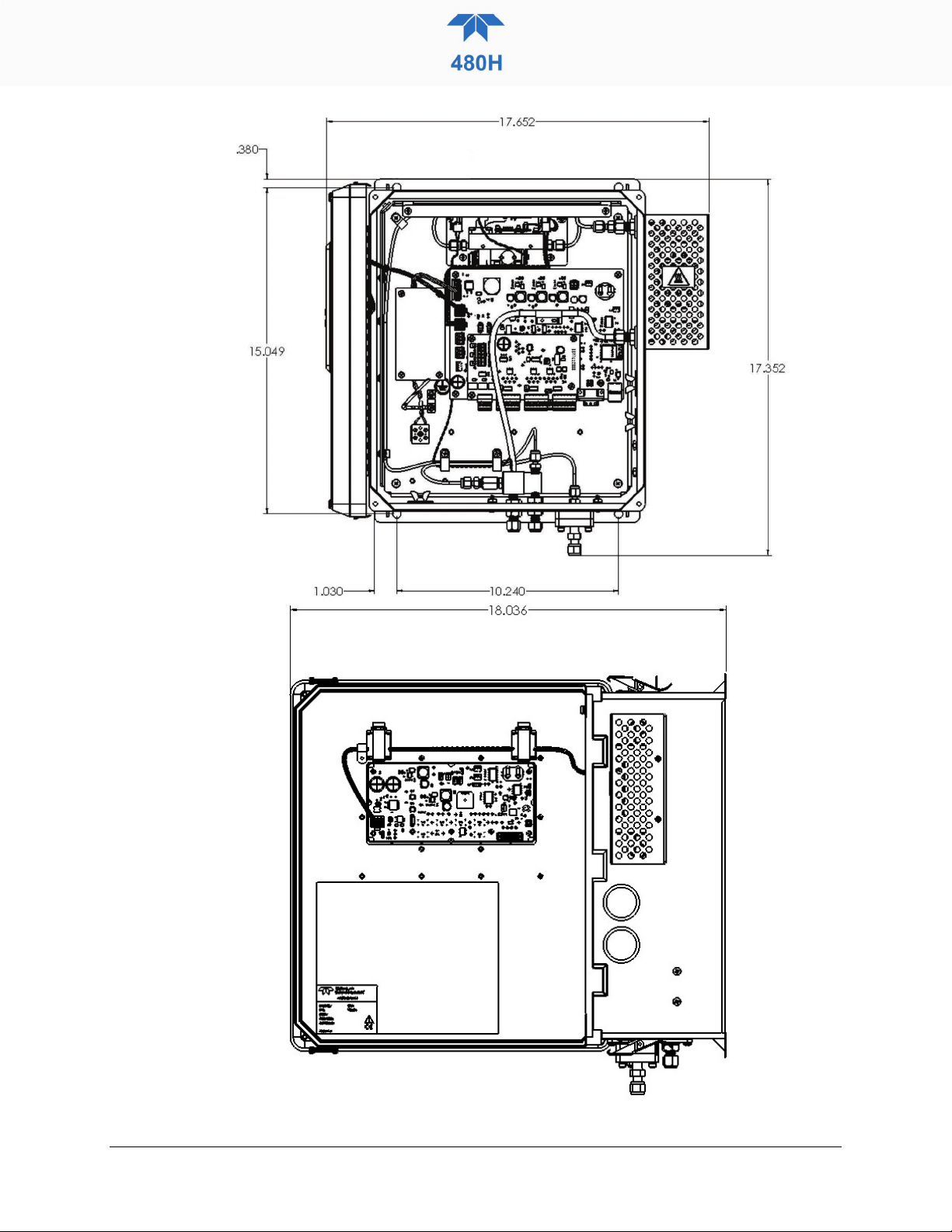
•The illustrations in Figure 3-2 show the mounting dimensions and the
locations of the four mounting holes, which are 0.32” (8.128 mm)
diameter
•All four mounting holes should be used to secure the monitor.
•If using bolts, ensure they are stainless steel, 5/16” (8 mm) diameter,
capable of supporting 20 lbs each.
09421A DCN8343 Teledyne API Model 480H O3Monitor User Manual 15
16 Teledyne API Model 480H O3Monitor User Manual 09421A DCN8343
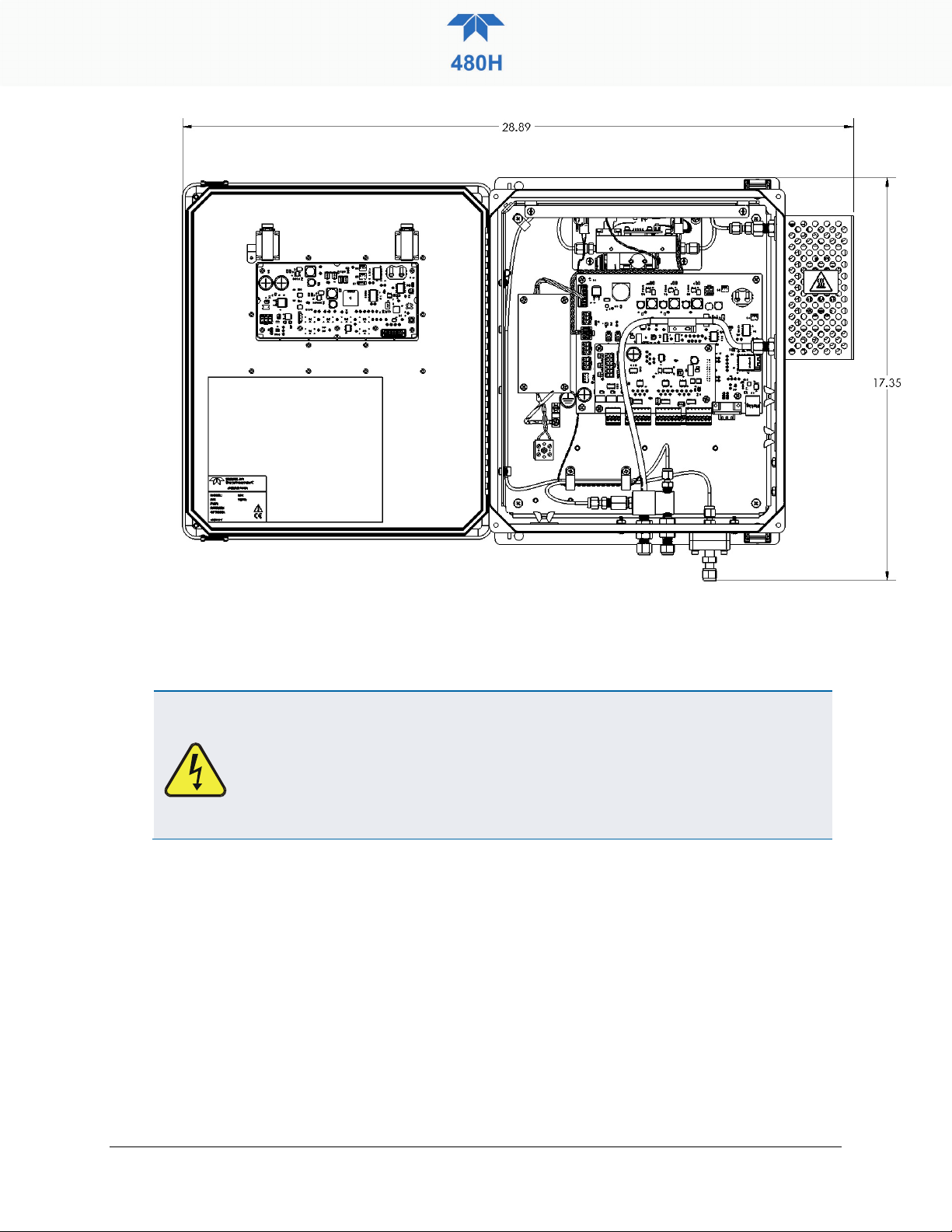
Figure 3-2. 480H Dimensions
3.3. AC POWER CONNECTION
WARNING – Electrical Shock Hazard
Disconnect power to the AC mains before making or removing any electrical
connections to the monitor.
A proper earth ground connection must be made to the receptacle labeled
“Earth Ground” on the 3-pin AC connector. Failure to do so may result in a
shock hazard and malfunction of the monitor.
3.3.1. WIRING REQUIREMENTS
Use appropriate wiring rated for this type of equipment, ensuring that it meets local
and national safety and building requirements.
Ensure that overcurrent protection is used (a 5 A circuit breaker is
recommended), and that it fulfills the following requirements:
•be located as near to the instrument as possible
•quickly and easily accessible
•clearly labeled as the disconnecting device for this instrument
09421A DCN8343 Teledyne API Model 480H O3Monitor User Manual 17
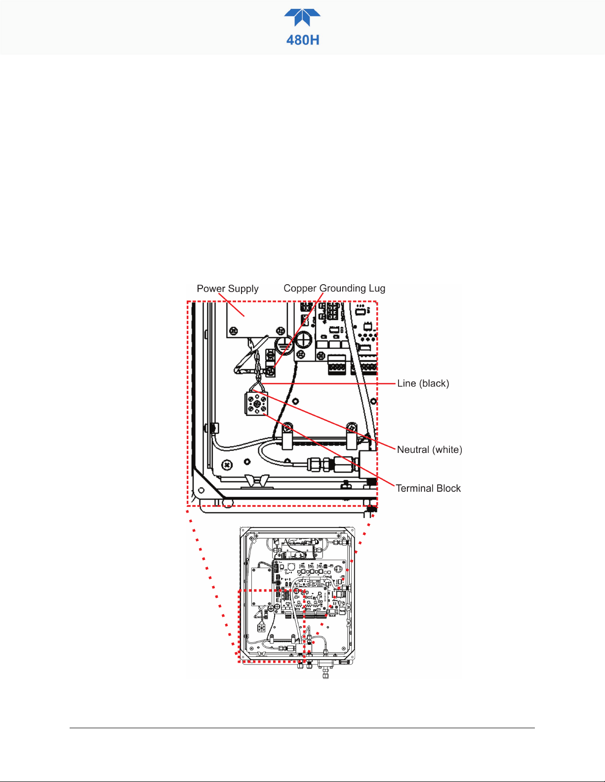
3.3.2. WIRING INSTRUCTIONS
1. Install a ½” conduit fitting for routing the electrical wiring into the monitor
through the hole provided in the bottom face of the NEMA enclosure; an
appropriate sealed conduit connector should be used.
2. Hard-wire the electrical connection to the terminal block and grounding lug on
the chassis. AC power connection to the monitor should be made with 12-14
AWG stranded copper wire, connected to the monitor as follows:
•Earth Ground (green):Connect the earth ground wire to the copper grounding lug
•Line (Black):Connect the Line wire to the terminal block directly across
from the black wire that leads to the power supply
•Neutral (White):Connect the Neutral wire to the terminal block directly
across from the white wire that leads to the power supply.
Figure 3-3. AC Power Connection to Monitor

18 Teledyne API Model 480H O3Monitor User Manual 09421A DCN8343
1. Connect the power cord to an appropriate power outlet or hardwired connection (see
the serial number tag for correct voltage and frequency).
WARNING
Verify that the instrument specification for proper line
voltage and frequency is followed. Observe local electrical
codes when connecting power to the monitor.
2. Turn on the 480L by applying power to the monitor. The front panel display will light
and display a Teledyne splash screen. The home screen will display the ozone
concentration and flow after the monitor begins taking stable readings.
3.4. ELECTRICAL I/O CONNECTIONS
The I/O connectors are located internally in the instrument. See Figure 3-4 for their
locations. Connection to these terminals is usually made via a conduit connection to
the enclosure. There are two conduit penetrations on the enclosure, and an
additional penetration can be added to one of the walls of the enclosure if needed.
Table of contents
Other TELEDYNE API Monitor manuals


