Teledyne Lecroy PCI Express Gen4 x16 EDSFF User manual

Introduction
Use this document for quick installation and setup.
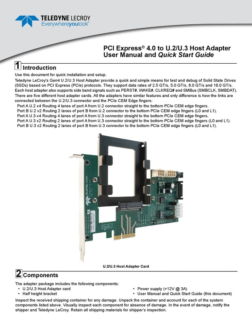
Teledyne LeCroy's PCIe Express Gen4 x16 EDSFF Host Adapter provides a quick and simple means for test and debug of
EDSFF form factor Solid State Drives (SSDs) based on PCI Express (PCIe) protocols. They support data rates of 2.5 GT/s,
5.0 GT/s, 8.0 GT/s and 16.0 GT/s. Each host adapter also supports side band signals such as PERST#, CLKREQ# and
SMBus (SMBCLK, SMBDAT).
Two host adapters with identical functionality support the different mechanical form factors E1.L (PE-1002-2-X16Host-X)
with a long bracket and E1.S (PE-1002-2-X16Host2-X) with a short bracket.
PCI Express Gen4 x16 EDSFF Host Adapter Card (bracket not installed)
1
Components
The adapter package includes the following components:
• Gen4 x16 EDSFF Host Adapter card
• Long or short device bracket depending on configura-
tion
• Adapter for Caseless EDSFF
• Screws for bracket (PN 42A0000001238)
• Screws for caseless adapter (PN 42A0000009442)
• Power Adapter (+12V @ 3A)
• User Manual and Quick Start Guide (this document)
2
PCI Express® Gen4 x16 EDSFF
Host Adapter
User Manual and Quick Start Guide
Inspect the received shipping container for any damage. Unpack the container and account for each of the system
components listed above. Visually inspect each component for absence of damage. In the event of damage, notify the
shipper and Teledyne LeCroy. Retain all shipping materials for shipper’s inspection.

Brackets and Adapter
Short Bracket 4.1"
PN: 931115-00
Long Bracket 12"
PN: 931097-00
Caseless
Adapter 4.5"
PN: 931094-00
(Drawings not to scale)
3
Assembly Steps
Before using the adapter make sure the device bracket is installed as instructed.
Attach the bracket to the EDSFF Interposer using four (4) supplied screws (PN: 42A0000001238), using a Phillips-head
screw driver. See figure below.
4

Attaching Short Bracket to Host Adapter PCB
Attaching Long Bracket to Host Adapter PCB
Screw Part Number
42A0000001238
Screw Part Number
42A0000001238

An optional adapter is provided for cases when testing a caseless EDSFF device. The device needs to be secure to the
adapter before it can slide in to the host adapter bracket. Attach the caseless EDSFF Device to the adapter using four (4)
supplied screws.
Attaching Caseless EDSFF Device to Host Adapter
Adapter for Caseless EDSFF Device
Caseless EDSFF Device
Connections
Perform to the following steps to connect each Gen4 x16 EDSFF Host Adapter (see the sample image below):
1. Slide the EDSFF memory device into the device bracket and carefully push it into it’s mating connector on the EDSFF
Host Adapter.
2. Make sure the power for the DUT is sourced correctly using switches SW12 (3.3V Source), SW11 (12V Source) and
SW15 (12V Power to DUT).
3. The factory default positions for SW5 (Lane Width Configuration): SW5.1 OFF, SW5.2 ON, SW5.3 OFF, SW5.4 OFF.
4. SW4 shunt 1 -> 2 for single port operation or shunt 2 -> 3 for dual port operation.
5. SW7 is ON for Activity LED.
6. SW10 is ON for DUT Power Status LED.
7. The PERST#/CLKREQ# control function is set by SW 6.
8. Plug the adapter with the device under test in any PCI Express slot.
9. Connect the power supply to the external power jack (J15) if needed.
5
Screw Part Number
42A0000009442

PCIe Slot from Host System Under Test
Caseless EDSFF Device inserted into short bracket on Gen4 x16 EDSFF Host Adapter
Switch Settings
Table 1: SW4
Note: Controls DUALPORTEN# sideband signal for single vs. dual
port operation.
Table 2: SW5
Note: Configure the PCIe Host Connector for the selected link width.
Table 3: SW6
Note: PERST#/CLKREQ# is multiplexed in EDSFF connector. In
Single Port mode (SW4), this signal acts as CLKREQ# signal. In
Dual Port mode(SW4) this sideband signal acts as PERST#.
Table 4: SW7
Note: Control for the LED/ACTIVITY sideband signal on EDSSF
connector. ACTIVITY is an input signal to the Host and is reserved
for future use. LED is active high output signal, used to drive Amber
LED from the Host. The header provides ability to drive this signal
high.
SW4 Single/Dual Port Operation
Shunt 1 – 2 SINGLE PORT
Shunt 2 – 3 DUAL PORT
SW5.1 SW5.2 SW5.3 SW5.4
Lane Width
Configuration
ON OFF OFF OFF PCIe x1
OFF ON OFF OFF PCIe x4
OFF OFF ON OFF PCIe x8
OFF OFF OFF ON PCIe x16
SW6 Control CLKREQ# or PERST#
Shunt 1 – 2 CLKREQ#
Shunt 2 – 3 PERST1#
SW7 Activity LED
Closed LED ON
Open LED OFF
SW7
SW15
SW6 SW10
SW4
SW5
SW12
SW11
EDSSF DUT
Device Bracket
J15 +12V@3A
from Power Adapter
6

Table 5: SW10
Note: The switch provides the ability toisolate these status indication
LEDs on this adapter and restrict the LEDs from power drawing.
SW10 ON means LEDs connected to the DUT power will be ON,
SW10 OFF means that the LEDS are disabled and drawing no
current.
Table 6: SW11
Note: Switch used to select the 12V power source for the EDSFF
Connector.
Table 7: SW12
Note: This switch is used to select the 3.3V power source for on
board circuitry in host adapter. 3.3V source could be either regulated
supply or from the PCIe slot (3P3V_Host).
Table 8: SW15
Note: Jumper closed for PWRDIS signal is enabled, which indicates
the device to shut off 12V and related circuitry. Open for normal
operation.
SW10 DUT PWR STATUS LED
ON CONNECTED
OFF DISCONNECTED
SW11 12V Source
12V EXT 12V from J15
12V HOST 12V from PCIe connector
SW12 3.3V Source
3P3V EXT 3.3V Regulated from J15
3P3V HOST 3.3V from PCIe Connector
SW15 12V Power to RSSD
Closed POWER DISABLED
Open POWER ENABLED
Available Test Points
Test Point
Number Test Point Name Description
TP7 CLK_BUF_SM_DATA Design specific, Provided
for bring up test
TP10 CLK_BUF_SM_CLK Design specific, Provided
for bring up test
TP23,T24,TP25 Ground Digital Ground
TP36 SMBRST#
RSSD Sideband signal;
Reset for management
interface. This is output
from host
TP38 MFG_B7 Manufacturing mode for
host
TP39 RFU_B8 Reserved for future use
TP41 LED_ACTIVITY
LED: Active high output to
drive amber LED state.
Activity: Active high input
signal will be used by
device to provide the
status of data transfer to
host.
TP42 PWRDIS
Power disable output
signal from host; Provided
SW15 jumper option to
control this signal
TP43 WAKE#
PCIe wake signal. It is not
defined in the RSSD
specification.
Test Point
Number
Test Point
Name Description
TP60 P3P3V_EXT 3.3V external supply
TP61 12V_Host 12 V input from the host PCIe
connector
TP62 12V_External
input 12V input from DC Jack
TP63 3P3V_HOST 3.3V input from the host PCIe
connector
TP64 RFU_B68 Reserved for future use
TP65 RFU_B69 Reserved for future use
TP67 RFU_A68 Reserved for future use
TP68 RFU_A69 Reserved for future use
TP69 RFU_A70 Reserved for future use
TP70 RFU_A42 Reserved for future use
TP71 12.0V Out
12V output from switch; either DC
jack input or PCIe slot power will
be selected based on the switch
selection
TP72 3.3V Out
12V output from switch; either DC
jack input or PCIe slot power will
be selected based on the switch
selection
7
Swapping the Full Height Bracket for the Half Height Bracket
Locate the two screws on the front of the Host Adapter securing the Full Height Bracket.
Using a Phillips head screw driver, remove the two screws that secure the full height bracket. Save the screws for
installation of the half height bracket.
Gen4 x16 RSSD Host Adapter with Full Height Bracket: Attached and Removed
Locate the Half height bracket and the two screws from the disassembly process.
Using a Phillips head screw driver use the two screws from the disassembly process to secure the half height bracket to the
Host Adapter. See drawings below.
Gen4 x16 RSSD Host Adapter with Half Height Bracket: Detached and Secured
8

Environmental Conditions
• Temperature: Operating 32° F to 122° F (0° C to 50° C)
• Temperature: Non-Operating 14° F to 176° F (-10° C to 80° C)
• Humidity: Operating 10% to 90% RH (non-condensing)
Copyright
© 2019 Teledyne LeCroy, Inc. All rights reserved. Part Number: 930955-00 Rev C
This document may be printed and reproduced without additional permission, but all copies should contain this copyright notice.
Trademarks and Servicemarks
Teledyne LeCroy is a trademark of Teledyne LeCroy. All other
trademarks are property of their respective companies.
Changes
Product specifications are subject to change without notice.
Teledyne LeCroy reserves the right to revise the information in this
document without notice or penalty.
Teledyne LeCroy Customer Support
Online Download
Periodically check the Teledyne LeCroy Protocol Solutions Group
web site for software updates and other support related to this
product. Software updates are available to users with a current
Maintenance Agreement.
Web: teledynelecroy.com/tm/software/PCIe
E-mail: [email protected]
Support: teledynelecroy.com/support/contact
9
Table of contents
Other Teledyne Lecroy Host Adapter manuals
Popular Host Adapter manuals by other brands

Qlogic
Qlogic SANblade QLA2310F Specifications

Savant
Savant SAV-CRU-0600 Quick reference guide

HighPoint
HighPoint RocketRAID 2720C2 Quick installation guide

MCC
MCC IPort MIIC-201D/U user guide

ATTO Technology
ATTO Technology ATTO Celerity FC-41XS Specifications

ATTO Technology
ATTO Technology ExpressPCI UL4S Technical specifications