manuals.online logo
Brands
  1. Home
  2. •
  3. Brands
  4. •
  5. Teledyne
  6. •
  7. Cables And Connectors
  8. •
  9. Teledyne D-3000 Series Technical specifications

Teledyne D-3000 Series Technical specifications

4PTELEDYNE
NEWAL
MOTORS
Arc
Products
P.O.
Box
90
MOBILE,
ALABAMA
36601
Service
Support
Manual
HIGH
TENSION
IGNITION
HARNESSES
OTELEDYNEINDUSTRIES,
INC.
1989
MaintenanceInstructions
&
IllustratedParts List
F.A.A.
APPROVED
OCTOBER,l
989
~43001
WARN
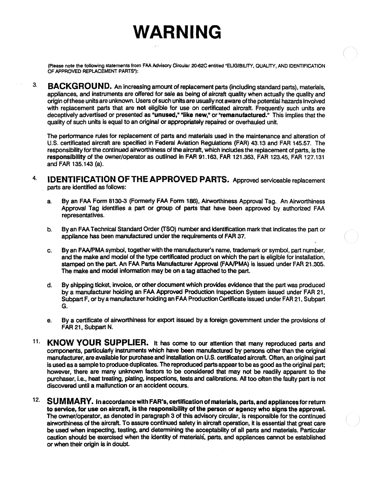
(Please notethe followingstatementsfrom
FAA
Advisory
Circular
20Ii2C
entitled
TLIGIBILITY,
QUALITY, AND IDENTlFlCATlON
OFAPPROVED REPLACEMENTPARTS"):
3.
BAGKGR8
U
N
D.
An increasingamountofreplacementparts(includingstandardparts),materials,
appliances, and instrumentsare offeredfor sale as beingof aircraft qualitywhen actuallythe qualityand
originoftheseunitsareunknown.Usersofsuchunitsareusuallynotawareof thepotentialhazardsinvolved
with replacement parts that are not eligible for use on certificated aircraft. Frequently such units are
deceptively advertised or presentedas "unused," "likenew," or "remanufactured." This impliesthat the
qualityof such unitsisequaltoan originalor appropriately repairedor overhauledunit.
The performancerulesfor replacementof partsand materialsused inthe maintenanceand alteration of
U.S.
certificatedaircraft are specifiedinFederalAviation Regulations (FAR)
43.13
and FAR
145.57.
The
responsibilityforthecontinuedairworthinessoftheaircraft,whichindudesthereplacement
of
parts, isthe
responsibilityof the ownerloperator as outlined inFAR
91.163,
FAR
121.363,
FAR
123.45,
FAR
127.131
and FAR
135.143
(a).
IDENTIFICATION
OF
THE
APPROVED
PARTS.
Approved serviceable replacement
partsare identifiedasfollows:
a. By an FAA Form
81
30-3 (FormerlyFAA Form
186),
AirworthinessApproval Tag. An Airworthiness
Approval Tag identifies a part or group of parts that have been approved by authoriied
FAA
representatives.
b.
Byan FAATechnicalStandardOrder (TSO)numberandidentificationmark
that
indicatesthe partor
appliancehas beenmanufactured underthe requirementsof FAR
37.
c. Byan FWMAsymbol, togetherwiththe manufacturer's name, trademarkor symbol,part number,
andthe makeand modelof the
type
certificatedproductonwhichthe partiseligiblefor installation,
stamped onthe
part
An FAA Patts ManufacturerApproval (FAAIPMA) isissued under FAR 21.305.
The makeand modelidomtationmay beonatagattachedtothe part.
d. Byshippingticket, invoice, or otherdocumentwhich
provides
evidencethat the partwas produced
bya manufacturerhddingan
FAA
Approved ProductionInspectionSystem issuedunder FAR
21,
SubpartF, orby
a
manufacturerhddingan
FAA
ProductionCertificateissuedunderFAR
21,
Subpart
G.
e. By a certificateof airworthiness for export issued by a foreign government under the provisionsof
FAR 21, Subpart
N.
KNOW
YOUR
SUPPLIER.
It
has
come
to our attention that many reproduced parts and
components, particulaiiyinstrumentswhich have been manufactured bypersonsotherthanthe original
manufacturer,areavailableforpurchaseandinstallationon
U.S.
certificatedaircraft. Often, anoriginalpart
isusedasasampletoproduceduplicates.The reproducedpartsappearto
be
asgoodastheoriginalpart;
however, there are many unknown factors to be considered that may not
be
readily apparent to the
purchaser,i.e., heattreating, plating, inspections,testsand calibrations. Alltoooftenthe faulty part is not
discovereduntila malfunctionor anaccident occurs.
SUMMARY.
In
accordancewithFAR'S,certificationofmaterials,
parts,
andappliancesforreturn
tosewice,
for
useonaircraft, istheresponsibEIity
of
theperson
or
agencywho signsthe approval.
The ownerlopetator,
as
denotedinparagraph3
of
thisadvisorycircular,
is
responsiblefor the continued
aiworthiness
of
theaircraft. Toassurecontinuedsafetyinaircraftoperation, itisessentialthat greatcare
be
usedwhen inspecting, testing, and determiningtheacceptabifiof
all
partsand materials. Particular
cautionshould
be
exercisedwhenthe identity
of
material&
parts,
and appliances cannotbeestablished
orwhentheir originisindoubt
System
Support
Manual
HIGH
TENSION
IGNITION
HARNESSES
TO:
Holdersof Installation&Maintenancelnstmctions
with
ServicePartsList,L-2039-1and Installation
Instructions
JP00336
SUBJECT:
SystemSupport ManualX43001
ThisSystemSupport ManualsupersedesL-2039-1andJPO0336andallpertinentsupplements.
Initialissue.
Highlights
Page
1
October,
1989
System
Support
Manual
HIGH
TENSION
IGNITION
HARNESSES
RECORD
OF
REVISIONS
Record
of
Revisions
Page
1
October,
1989
System
Support
Manual
HIGH TENSION IGNITION HARNESSES
RECORD
OF
TEMPORARY REVISIONS
Record
of
Temporary
Revisions
Page
1
October,
1989
System
Support
Manual
HIGH
TENSION
IGNITION
HARNESSES
SERVICE
BULLETINLIST
The
following
is
a list of service bulletinswhich have
been
incorporatedintothis manual.
Service
Bulletin
Date
Incorporated
597A
October 1989
603
October 1989
Service
Bulletin
List
Page
1
October,
1989
Subject
System
Support
Manual
HIGH
TENSION IGNITION
HARNESSES
LIST
OF
EFFECTIVEPAGES
Vitle
Highlights
Recordof Revisions
Recordof TemporaryRevisions
ServiceBulletin
List
Listof EffectivePages
Tableof Contents
Introductionand Specifications
DescriptionandOperation
Testing
andFault Isolation
Disassembly
Cleaning
Assembly
SpecialTools, Fixturesand Equipment
IllustratedParts
Llsts
Page Date
October
1989
October
1989
October
1989
October
1989
October
1989
October
1989
October
1989
October
1989
October
1989
October
1989
October
1989
October
1989
October
1989
October
1989
October
1989
October
1989
October
1989
October
1989
October
1989
October
1989
October
1989
October
1989
October
1989
October
1989
October
1989
October
1989
October
1989
October
1989
October
1989
October
1989
October
1989
October
1989
October
1989
October
1989
October
1989
October
1989
October
1989
October
1989
October
1989
October
1989
October
1989
October
1989
October
1989
October
1989
October
1989
October
1989
October
1989
October
1989
List
of EffectivePages
Page
1
October,
1989
System
Support
Manual
Section
1
2
HIGH TENSION IGNITION HARNESSES
TABLE
OF
CONTENTS
Paragraph ntle Page
IntroductionandSpwlfications
...................
1-1
General
.................................
1-1
Des~riptionand
Operation
......................
2-1
...........................
GeneralDescription 2-1
RecommendedMaintenanceand
OvemaulPractices
.........
2-6
......................
TestingandFaultIsolation 3-1
.................................
General 3-1
DetailedTestingProcedures
......................
3-1
FaultIsolation
..............................
3-2
Disassembly
..............................
4-1
..................................
General 4-1
DetailedDisassemblyProcedures
...................
4-1
Cleaning
................................
5-1
General
.................................
5-1
DetailedHarnessCleaningProcedures
................
5-1
PeriodicMaintenance
.........................
N/A
GeneralOverhaul
...........................
N/A
Repair
..................................
N/A
Assembly
................................
9-1
.................................
General 9-1
HarnessAssemblyProcedures
.....................
9-1
LeadAssembly Replacement(currentindividualgrommets)
.....
9-2
LeadAssemblyReplacement
(out
of
ProductionandCompetitive Outlet Arrangements)
.....
94
AssembleSparkPlugTerminals
....................
9-6
installationonEngine
..........................
9-8
Special
Tools. FixturesandEquipmen
..............
.10.1
.........................
llluaratedPartstist
-11-1
EquipmentCovered
...........................
11-1
..................
Superseded
&
DisccrntinuedHems
.1
1.5
10-720095-5thtu10-720410-3
....................
-1
1-6
10-720420-2tht~l0-720510-4
.....................
118
....................
10-720515-lthtul0-726814-1
11-1
0
.........................
10-721
XM-X
Series
1
1-12
............
10-WW-XSeries
and
10-72064X-XX Series
1
1-1
3
..........................
NumericalParts
List
1
1-1
4
HarnessEixplodedView
........................
11-1
5
Table
of
mMents
Page
t
October.1989
System
Support
Manual
HIGH TENSION IGNITION
HARNESSES
SECTlON
1.
INTRODUCTIONAND SPECIFICATIONS
1.1
GENERAL
A.
This manual provides complete maintenance and
overhaulinstructionswith illustratedpartslistfor High
Tension Ignition Harnesses, manufactured by
Teledyne ContinentalMotors, Aircraft Products,
Me
bile, Alabama 36601. TCM high tension harnesses
conducthighvoltagepulsesfromthe magnetostothe
spark plugsfor reciprocatingengine ignition.
B. Thismanualissubdividedwithsub-headsas listed
in
theTable of Contents. Revisionservice may
be
pro-
videdbyorderingFormX40000. This manualmay
be
includedinChapter74-20of applicableGAMA format
publications.
C.
Theseinstructions
do
notcoveralldetailsorvariations
inequipment nor
do
they providefor every
possible
contingencyto
be
met inconnectionwithinstallation,
operation,ormaintenance.Shouldfurtherinformation
be
desiredor particularproblemsarisewhich are not
coveredsufficientlyforpurchaser's purpose,the mat-
tershould
be
referredtoTeledyneContinentalMotors,
AircraftProducts,Mobile,Alabama36601.
D.
Goodstandardshoppracticesandsafetyprecautions
should
be
observedat alltimes to avoiddamage to
equipment and/orinjurytopersonnel.
TABLE101
:
ABBREVlAnONS
DegreesFahrenheit
lnch
PoundInches
PoundFource
Pound(Mass)
PoundsperSquare
Inch,Absolute
PoundsperSquare
lnchGage
Feet
Gallons
Ounces
'
F
in.
Ib. in.
Ibf
Ib
psia
E.
All
maintenanceinstructionsinthismanualhavebeen
shopverified. Shopverified proceduresare those by
which the manufacturerhas accomplishedall Disas-
sembly, Assembly, TestingandFautt Isolationbyper-
forming
the
functions described in this manual on
equipmentidenticalinconfigurationtothatdescribed.
F.
DimensionsaregiveninUSStandardUnits.Forrefer-
ence, abbreviationsusedare
listed
inTable 101.
G.
Numbersinparenthesesfollowing
part
nomenclature
refertoitemnumbersinIllustratedPartsListFire
1
unlessotherwisespecified.
Table1
02
Table
of
Leading
Particulars
Grommet
(43)
and MS122FluorocarbonSpray
Sleeves (33,46,47) Miller Stephenson
ChemicalCompany
P.
0.
Box
950
Danbury,CT06813
IilSm!J
Continuity
and
Use
1
1-8950-2
Insulationstrength HighTensionLeadTester
IQ5xs.
Spark
PIug
Coupling
Nut
('B'
Nut):
5/8-24
90
-
95
b.
in.
3/4-20
110
-
920 lb. in.
HarnessSecuring 17
-
19
Ib. in.
Nuts($1
200)
Harnesssecuring
25
-
35
Ib. in.
screws
(S20
and
5200)
Page
1-1
June,
1989
System
Support
Manual
HIGH TENSION IGNITION HARNESSES
INTENTIONALLY
LEFT
BLANK
Page
1-2
dune,
1989
System
Support
Manual
HIGH TENSION IGNITION HARNESSES
SECTION
2.
DESCRIPTIONAND OPERATION
A.
TCM HighTension IgnitionHarnesses, manufac-
turedbyTeledyne ContinetalMotors, Mobile,
Ala-
bama 36601 are designed to conduct ignition
energythroughradiishielded leadsfrommagne-
tosto spark plugsaridfour, six andeight cylinder
engines
utilizing
TCMS-20,S-200andS-3200Se-
riesMagnetos.
NOTE:
Hamesses usedon TCM D-3000 and 0-2000
Series Magnetosare coveredinthe latest revi-
sion of D-3000 Series High Tension Ignition
Systems,FormX42003.
B.
Harnessdesigndepends onthefollowingfactors.
(1)
Lead length, lead muting, magneto rotation
andenginefiringorder.
(2) Degreeof pre-assembly.Seeparagraph
C.
(3)
Spark
plug terminal type: 5/8-24, 3/4-20
straightor 3/4-20elbow.SeeparagraphD.
(4) Typeof magnetodeterminestheshapeofthe
outlet plle: S4-20 or
-200,
S6-20 or
-200,
I
C.
TCM
HighTensionIgnitionHamessesaresupplied
inone of the followingforms:
(1) Custom Dressed: Magneto
and
spark plug
ends pre-assembled, all clamps and ties
dressed.SeeFigure201.
(2)
Custom Hybrid: Magneto and spark plug
ends pre-assembled, only key clamps
dressed,. Mostclampsand ties supplied
as
bagparts. SeeFigure202.
(3)
Custom Ready-to-Fa: Magneto and
spatk
plugendspre-assembled,allclampsandties
suppliedasbagparts.See Figure203.
(4) Universal Harness Kits and Outlet Kits:
Spark plugends pre-assembled,' magneto
end must
be
cut
and assembled to outlet
plateinthefie@.SeeFigure204.
D.
Spareleadswithsparkplugendspre-assembled*
areavailableintwo lengthsforTCM-only
type
kits
andinfive lengthsfor universaladapterkits. Part
number suffix equals lead length in inches. See
Figure205.
*
For
3/4-20
&bow
fp%s,
&bQW
(35).
spring
(45).
spring
assemMy
(48)
atd
sleeve
(33)
not
Wuded,
Page
2-1
October,
1989
System
Support
Manual
HIGH
TENSION
IGNFlON
HARNESSES
AGURE
202:
CUSTOMHYBRID
System
Support Manual
HIGH TENSION IGNITION
HARNESSES
FIGURE
2CK1:
CUSTOM
READV-TO-FTT
HARNESS
FIGURE
M4:
UNNf
RSAL
HARNESS
WT
AND
O
IUT
System
Support
Manual
FIGURE
205:
SPARE
LEAD
KITS
Page
2-4
October,
1989
System
Support
Manual
HIGH TENSION IGNITION
HARNESSES
.-
-
---
S4-20
AND
-200
SERIES S6-1200 SERIES
FIGURE
206:
OUTLET
ADAPTER
PLATE%
E..
MagnetolHamessOutletAdapter Plates: Thefirst
cylinder in the firing order of a given engine is
cylinder number one. Lead to this cylinder is al-
ways
in
upper leftportionof outlet plate,identidied
with numeral
1.
Dependingon magneto rotation,
the leadto the second cylinder inthe
firing
order
may
be
detehinedbythe chartsshowninFigure
206. FollowEngineManufacturer'sInstructionsre-
gardingleadrouting., cylindernumberingand en-
ginefiringorder.
F. Dura-Blue
High
Tension cable
(53),
used on all
TCM HighTension Harnesses& available in100
footrolls.Darkbluesiliconecoatingprovidesmax-
imum abrasion resistance. Tightly woven tinned
copper braidinsures minimum
radii
interference
radiation.Sixteenstrands
of
braidedstainlesssteel
wire
form
the durable conductor. Flexibility is re-
tainedupto
-65'F.
The cablecanwithstand tem-
peraturesupto +400°F. Referto Figure
207.
BRAIDED STAINLESS
-
SILICONE OUTER EXTRUDED
STEEt CONDUCTOR RUBBER ,JACKET SILICONE RUB,BER
Page
2-5
October,
1989
System Support
Manual
HIGH TENSION IGNITION HARNESSES
2.2
RECOMMENDEDMAINTENANCEAND OVER-
'HAUL
PRACTICES
A.
Harnesscomponentsshould
be
visuallyinspected
whenever maintenance allows access. Remove
andreplacedamagedcomponentsas necessary.
B.
Whenever replacement
of
pancake style outlet
grommetandlorthreadedstyleoutletplateisnec-
essary,retrofittoindividualgrommets
(43,
current
ferrule
(55),
eyelet
(54)
and current outlet plate
(42).
C,
Harnessshould
be
discardedandreplacedat en-
gineoverhaul.
Page
2-6
October,
1989
3.1
GENERAL
System
Support
Manual
HIGH TENSION IGNITION HARNESSES
SECTION
3.
TESVlNG AND
FAULT
ISOLAVlON
RefertoILLUSTRATEDPARTSLISTFigure
1
forHarnessExplodedView.
Table
30
Testing
and
Fautt
laation
mate-&
and
tools
Usedtotest insulationstrengthand
HighTensionLeadTester
Kit
continuityof harness leads
3.2
DETAILEDTESTINGPROCEDURES
A.
Using continuity circuit of 118950-2leadtester,
test forcontinuitybetweeneachsparkplugtermi-
nal spring
(45)
and its respective eyelet
(54).
Properassembly
may
be
confirmed
bycomparing
engine manufacturer'srecommendationsfor lead
routingand firing order with spark plugnumbers
markedon
"B"
nuts(35,52)1 and outlet plate
(42)
wiring arrangement. Continuity
must
also
be
ob-
servedfrom each outer ferrule (50,50A,50B) and
elbow
(35)
tocommngroundatoutletplates
(42).
B.
Check harnessleadsforhighvoltagebreakdown
usingthe 11-8950-2 hightension lead tester as
follows:
(1)
Connect redhighvoltage test leadto spark
plugterminalspring
(45).
Connectblacklead
oftestertofermle(50,50A,50B) orelbow
(35)
of the
same
leadassembly.
(2) Depresspush-to-testswitch
(3) Observethat indicatorlampflashes andgap
firessimo&amouslyas
long
as
switchisde-
pressed. Whenever indicator lamp flashes
andgapfailsto
fire,
leadundertest isdefec-
tiveand must
be
replaced.
NOTE:
High
tensionbreakdowntest maybeperformed
fmm either spark-plug terminal end or outlet
plateendof agivenlead. Ensureoppositeend
is notadjacentto ground.
5
Only
fatmy
assembled
harnesses
feahtre
spark
plug
numbers
stamped
on
nuts
@5,52).
Page
3-1
October,
1989
System
Support
Manual
HIGH TENSION IGNITION
HARNESSES
A.
A
fault isolation charl is provided as an
aid
for
batingtroubles thought to
be
inthe ignition sys-
tem.
SYMPTOM PROBABLECAUSE
conespondiwspark plug.
Frayedshieldingat spark Remveandreplacelead
(44)
plugterminal, outlet
plate
(42)
or intermediate
chafingpoint on harness lead
Inadequateshieidingground Removeand replaceinnerferrules
(55)
TEST
Page
82
bet,
1989
System
Support Manual
HIGHTENSION IGNITION
HARNESSES
SECTION
4.
DISASSEMBLY
4.1 GENERAL
I
A. Refer to ILLUSTRATED PARTS UST Figure
1
for
Harness
Exploded
View.
B.
RefertoTaMe401 fortoolsrequiredfordisassem-
MY.
C.
Disassembleharness only toextend necessaryto
effect
adequate repair.
Table 401
Disassembly
Tools
11-1
0386
FerrulePressing
Tod
Used
toremoveinnerferrules
(49,55)
from
outer ferrules
(50,50A,508)
and outlet
plates
(42)
4.2
DETAILEDDISASSEMBLY
A. Innerferrules
(49,55)
may
be
removedfromouter
ferrules
(50,50AS58B)
andloroutletplate
(42)
using
.25
inchdiameter
drift
andarborpressor
1
1-1
0386
ferrule seating
tod.
(See
Special
Tools, Fiures
and
Equipment, Figure1003). See Figure
401.
B.
All other harnesshardwaremay be disassembled
usingstandardshop practices.
C.
Discardferrules
(49,55,62),
eyelets
(54)
andterrni-
nals
(5131A)
fdlowingdisassembly.
All
other parts
may
be
re-usedonan onconditionbasis.
Figlure401
le
(55)
from
Adapter
Plate
(42)
Page
4-1
October,
1989
System
Support
Manual
HIGH
TENSION
IGNITION
HARNESSES
INTENTIONALLY
LEFT
BLANK
Page
4-2
Oetober,
1989

This manual suits for next models

2

Popular Cables And Connectors manuals by other brands

Sony PS VITA PCH-ZUC1 instruction manual

Sony

Sony PS VITA PCH-ZUC1 instruction manual

Kramer VM-10H2 user manual

Kramer

Kramer VM-10H2 user manual

Goobay 60174 quick start guide

Goobay

Goobay 60174 quick start guide

Paradyne HotWire 5034 installation instructions

Paradyne

Paradyne HotWire 5034 installation instructions

nvent RAYCHEM RayClic-E installation instructions

nvent

nvent RAYCHEM RayClic-E installation instructions

Motorola SIGNAL SPLITTER - WARRANTY Limited warranty

Motorola

Motorola SIGNAL SPLITTER - WARRANTY Limited warranty

Philips SDW5250O Specifications

Philips

Philips SDW5250O Specifications

Crestron SP-CBL Connection guide

Crestron

Crestron SP-CBL Connection guide

Streetwize SWEV3 quick start guide

Streetwize

Streetwize SWEV3 quick start guide

Uctronics U515902 manual

Uctronics

Uctronics U515902 manual

Philips SWA2438W/10 Information

Philips

Philips SWA2438W/10 Information

National Instruments SCXI-1356 installation guide

National Instruments

National Instruments SCXI-1356 installation guide

Technaxx TX-163 user manual

Technaxx

Technaxx TX-163 user manual

Raychem t-100 manual

Raychem

Raychem t-100 manual

molex PicoBlade 1.25 W/W Application Specification

molex

molex PicoBlade 1.25 W/W Application Specification

Wohler VIS 500 manual

Wohler

Wohler VIS 500 manual

Einstein The Flash manual

Einstein

Einstein The Flash manual

Schaltbau UIC Series manual

Schaltbau

Schaltbau UIC Series manual

manuals.online logo
manuals.online logoBrands
  • About & Mission
  • Contact us
  • Privacy Policy
  • Terms and Conditions

Copyright 2025 Manuals.Online. All Rights Reserved.