manuals.online logo
Brands
  1. Home
  2. •
  3. Brands
  4. •
  5. Teledyne
  6. •
  7. Water Pump
  8. •
  9. Teledyne ACCQPrep Guide

Teledyne ACCQPrep Guide

Information included herein is controlled by the Export Administration Regulations (EAR) and requires an export license, license exception or
other approval from the appropriate U.S. Government agency before being exported from the United States or provided to any foreign person.
Diversion contrary to U.S. law is prohibited.
ACCQPrep Pump Assembly
Replacement and HP150 to
HP125 Pump Assembly
Conversion Instructions
Instruction Sheet #69-5233-940
Revision A, Jan 2, 2020
Overview
The ACCQPrep replacement pump assembly contains
a pump sled assembled for a HP150 instrument, parts
to convert the pump assembly to be used on a HP125
instrument, and parts to convert the old Valco pump
bulkhead brackets and fittings to Swagelok on older
HP125 instruments. If the replacement pump assembly
is being installed on an HP150 configured ACCQPrep,
then no conversion work needs to be completed before
installing the replacement pump assembly.
Table 1: Parts List
Item Quantity
Replacement Pump Assembly 1
Swagelok Bulkhead Assembly 1
The table below lists additional items that are required
for the pump assembly conversion:
Table 2: Required Tools
Safety
The use of Personal Protective Equipment (PPE) is highly
encouraged due to potential contact with residual solvents.
Time Required:
Typical time required to perform the pump greasing is
approximately 1.5 hour.
Note
If the Swagelock Bulkhead Assembly (60-5237-141) will
be installed with the replacement pump, then use these
instructions to complete the work and ignore the
installation instructions (69-5233-941) that come with
the Swagelok Bulkhead Assembly.
Removing Solvent & Powering Down
the Instrument
1. Remove all solvent supply lines from the solvent
containers.
2. Remove the lower front cover of the instrument to
expose the front of the current pump assembly
3. Select Tools > Manual Control from the upper tabs
of the main screen of the instrument.
4. Set the Flow Path to “Prep HPLC column”. Set the
Flow Rate, ml/min to 50.
5. If the instrument does not include a Solvent Select Valve,
then proceed to Step 6, else Set Solvent A to one of the
plumbed solvent lines and Solvent B to another of the
plumbed solvent lines (ex: A1 - Methanol, B1-Water, etc.).
6. Press the Pump Solvent A button. Allow the pumps to
run until there is no longer solvent flowing to the bottom
of the A pumps. Press the Stop button. Press the Pump
Solvent B button and repeat this process for the B pumps.
7. Shutdown the instrument by toggling the red power
switch on the front of the instrument.
8. Wait 30 seconds after the touchscreen turns off and
then disconnect power to the instrument either by
disconnecting the power cable at the back of the
instrument or at the wall outlet.
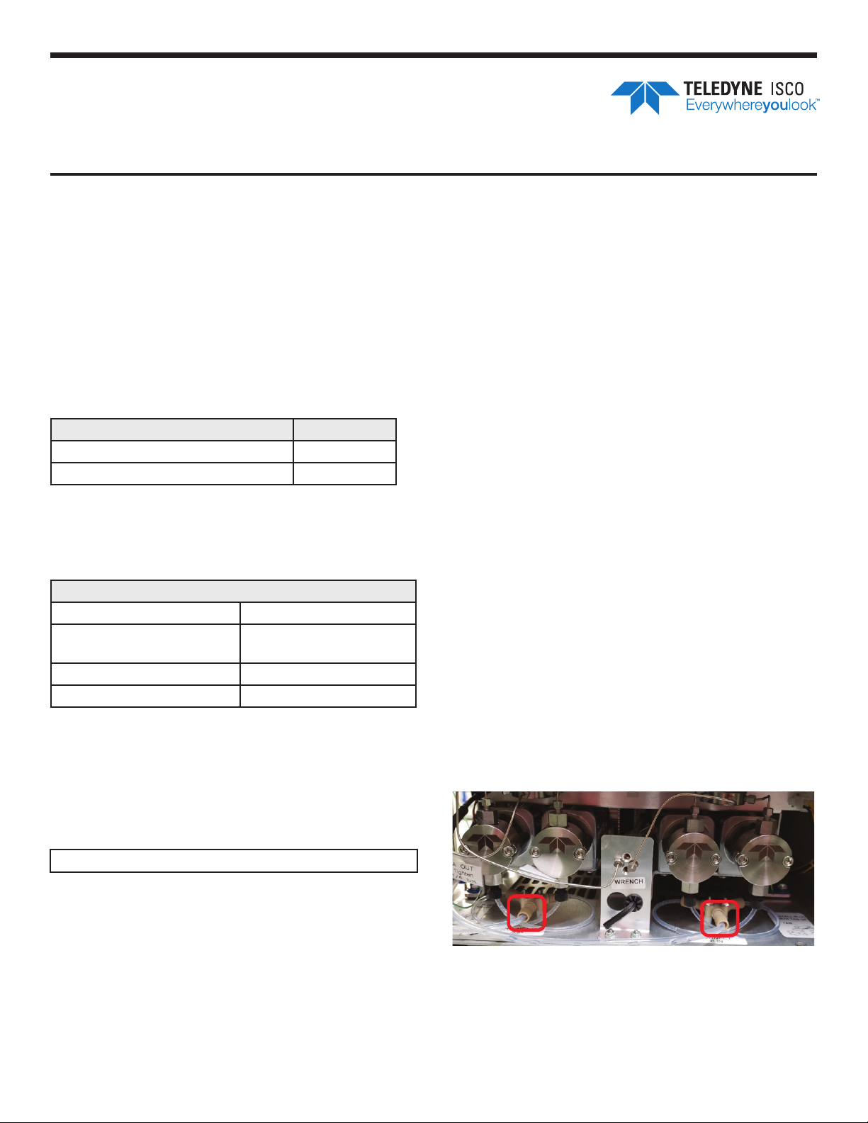
Removal of the Current Pump Assembly
1. With your fingers, disconnect the input tube at
Y-connector below each set of pumps (Figure 1). If the
fittings are too tight to be disconnected by hand, then
gently use a pliers to loosen the fitting enough to finish
disconnecting it by hand.
Figure 1: Y-Fitting inlet tubing
Item
#2 Phillips Screwdriver
1/8” Small Flathead
Screwdriver
5/16” Open End Wrench
1/4” Open End Wrench
Side Cutter
5/16” Nut Driver or
Rachet (optional)
Pliers
1/4” Rachet (optional)
Instruction Sheet #69-5233-940 Revision A, Jan 2, 2020
EAR-Controlled Technology Subject to Restrictions Contained on the Cover Page.
2. Using a 5/16” or 1/4” open end wrench (depending on
current configuration of the bulkhead connections),
disconnect the output of pumps A & B at the bulkhead
connection points. (Figure 2)
Figure 2: Bulkhead connections-Swagelok (left) Valco (right)
3. Disconnect the signal and power cables connected to
the pump assembly. (Figure 3).
Figure 3: Pump assembly electrical connection locations
4. Using the 3/16” Allen wrench attached to the front of
the pump assembly, remove the two screws that secure
the pump assembly to the instrument (Figure 4). Use
the Allen wrench on the replacement pump assembly if
it is missing from the current pump assembly.
Figure 4: Allen key and pump assembly securing screw
locations
5. Gently pull the pump assembly from the instrument.
Make sure not to damage any tubing or wiring
surrounding the pump assembly when slowly pulling
it out. (Figure 5)
Figure 5: Wiring and tubing locations highlighted
Caution
Monitor the RFID boards and wiring that is located
above the pump assembly as you remove it from the
instrument.The wiring can droop down, become caught
on the pump assembly, and damage the RFID boards
and wires. (Figure 6)
Figure 6: RFID boards above the pump assembly
6. If the pump bulkhead connections are currently
Swagelok on this instrument (Figure 7) and the
instrument is a HP125 (Figure 8), then the Installation
of Swagelok Bulkhead section can be skipped.
7. If the pump bulkhead connections are currently
Swagelok on this instrument (Figure 7) and
instrument is a HP150 (Figure 8), then the
Installation of Swagelok Bulkhead and
Converting Pump Assembly from HP150 to
HP125 Configuration sections can be skipped.
Figure 7: Swagelok style pump bulkhead connections
Instruction Sheet #69-5233-940 Revision A, Jan 2, 2020
EAR-Controlled Technology Subject to Restrictions Contained on the Cover Page.
Figure 8: Instrument configuration label
Installation of Swagelok Bulkhead
1. Using a 1/4” open end wrench, disconnect the upper
Valco bulkhead connections (Figure 9)
Figure 9: Upper bulkhead connections disconnected
2. Using a 5/16” open end wrench or rachet, remove the
three nuts attaching the bulkhead bracket to the frame
(Figure 10; red). Using a #2 Phillips screwdriver remove
the four screws attaching the bulkhead bracket to the
frame (Figure 10; yellow). The two lower screws must be
removed from the underside of the instrument.
Figure 10: Bulkhead fasteners
3. Install the new Swagelok bulkhead bracket in the same
location as the previous bracket and fasten it down
using the same nuts and screws removed in Step 2.
4. Using a #2 Phillips screwdriver, remove 8 screws
securing the left side panel and set the panel aside
(Figure 11)
Figure 11: Left side panel
5. Using a 1/4” open end wrench, disconnect one of the
upper Valco bulkhead connections at prime valve port
2 or 5 and remove the tubing from the instrument
(Figure 12)
Figure 12: Prime valve connections
6. Find the pre-swaged 11” stainless steel tubing in
the kit with the same label as the tubing that was
just pulled from the instrument. Using the original
tubing as a guide, bend the new tubing into the same
shape. This will make it easier to reinstall into the
instrument (Figure 13)
Instruction Sheet #69-5233-940 Revision A, Jan 2, 2020
EAR-Controlled Technology Subject to Restrictions Contained on the Cover Page.
Figure 13: Bulkhead to prime valve tubing
7. Install the newly bent tubing into the instrument,
secure the Valco fitting to the open port on the prime
valve by hand, and secure the Swagelok fitting to the
corresponding upper bulkhead connection port by
hand.
8. After both fittings are finger tight, use a 1/4” open end
wrench to tighten down the Valco fitting 1/8 – 1/4 a
turn and use a 5/16” open end wrench to tighten down
the Swagelok fitting 1/8 – 1/4 a turn to fully seat these
connections.
9. Repeat Steps 5 – 9 to replace the second tubing from the
pump bulkhead connection bracket to the prime valve
Converting the Pump Assembly from HP150
to HP125 Configuration
1. Using a 1/4” open end wrench or ratchet, remove the
4 nuts securing the two Y-connectors below each set of
pumps on the replacement pump assembly (Figure 14)
Figure 14: Pump inletY-connector
2. Disconnect the fitting on the bottom side of each of
the four pump heads (Figure 14)
3. Remove the Y-connectors and associated tubing from
the replacement pump assembly (Figure 15)
Figure 15:Y-connector and tubing removed
4. Install both sets of HP125 Y-connector and tubing on
the replacement pump assembly (Figure 16).
Figure 16: HP125 replacement tubing and Y-connector
5. Using a small 1/8” flathead screwdriver, adjust the
rotary switch on the left pump board from 3 to 1 and
adjust the rotary switch on the right pump board
from 4 to 2 (Figure 17)
Instruction Sheet #69-5233-940 Revision A, Jan 2, 2020
EAR-Controlled Technology Subject to Restrictions Contained on the Cover Page.
Figure 17: Pump board rotary switches
Installing the Replacement Pump Assembly
& Testing the Instrument
1. Write down the revision listed on the label of each of
the pump boards (Figure 18). Pump A is the left board
and Pump B is the right board. These values will be
entered in the Pump tab of Service menu when the
instrument is first powered on.
Figure 18: Pump board revision sticker
2. Gently slide the replacement pump assembly into the
instrument. Make sure not to damage any tubing or
wiring surrounding the pump assembly as it is being
slid into place. (Figure 5/6
Note
The two slots on the backside of a pump assembly align
with two stand-offs in the instrument opening near the
rear fans. If the pump assembly is correctly installed,
then the holes for the two front securing screws will be
lined up. If these holes are not aligned, then the pump
assembly rear slots are most likely not aligned with the
rear stand-offs.
3. Using the 3/16” Allen wrench attached to the front of the
pump assembly, install the two front screws to secure the
pump assembly to the instrument (Figure 4)
4. Connect the signal and power cables to the pump
assembly. (Figure 3)
5. Connect the output of pumps A & B to the lower
bulkhead connection points (Figure 2). After finger
tightening the Swagelok fittings, use a 5/16” open end
wrench to tighten down each fitting a 1/8 – 1/4 a turn
to fully seat these connections.
6. Connect the solvent inlet tube at Y-connector below
each set of pumps (Figure 1).
7. Connect the power cable at the back of the instrument
and/or at the wall outlet to provide power to the
instrument.
8. Power on the instrument by toggling the red power
switch on the front of the instrument.
9. In Help > Service, type in the password “accqprep”
to access the Service menu (Figure 19)
Figure 19: Service menu location
10. Located in the upper right corner of the Pumps tab is
the “Pressure transducer calibration” section (Figure
20). Enter in the revision for each of the pump boards.
If the revision listed on a pump board label is A-E,
then select “Rev E or Earlier”. If the revision listed
on the pump board label is F-Z, then select “Rev F or
Later”. Press the Save button.
Figure 20: Pump tab of the Service menu
Teledyne ISCO
P.O. Box 82531, Lincoln, Nebraska, 68501 USA
Toll-free: (800) 228-4373 • Phone: (402) 464-0231 • Fax: (402) 465-3091
Teledyne ISCO is continually improving its products and reserves the right to change product
specifications, replacement parts, schematics, and instructions without notice.
Instruction Sheet #69-5233-940 Revision A, Jan 2, 2020
EAR-Controlled Technology Subject to Restrictions Contained on the Cover Page.
11. Press the Exit button in the upper righthand corner of
the Service menu to save all changes and reboot to the
main screen
12. Install all solvent supply lines into the solvent
containers.
13. Turn the prime knob on the front of the instrument to
the “Prime” position and press the OK button in the
pop-up window to prime the pumps with solvent. Turn
prime knob back to the “Run” position when automated
prime is complete. Repeat this step if the solvent inlet
tubing is not filled with solvent (air bubbles)
14. Install a column on the instrument. Install restrictive
capillary tubing in place of a column if one is not
available.
15. In Tools > Manual Control begin running solvent
through the instrument. When the pressure stabilizes,
begin increasing the flow rate to increase pressure
within the instrument. At each incremental change
in flowrate/pressure, check all stainless-steel tubing
connections on the pump assembly and bulkhead
bracket. If you performed the Installation of Swagelok
Bulkhead section, then perform the same leak check
on the prime valve fittings.
Note
If there is any solvent leaking from a fitting, tighten the
fitting further and continue the leak check up to the
maximum pressure rated for the installed column or
maximum pressure set in the configuration menu.
16. Install the lower front cover of the instrument and
install the left side panel if it was also removed
17. Pump assembly replacement is complete

This manual suits for next models

2

Other Teledyne Water Pump manuals

Teledyne SyriXus 65x Operating instructions

Teledyne

Teledyne SyriXus 65x Operating instructions

Teledyne D series Operating instructions

Teledyne

Teledyne D series Operating instructions

Popular Water Pump manuals by other brands

Master 540155 owner's manual

Master

Master 540155 owner's manual

Beckett BK22UL quick start guide

Beckett

Beckett BK22UL quick start guide

BVA Hydraulics PU55M3N025C instruction manual

BVA Hydraulics

BVA Hydraulics PU55M3N025C instruction manual

PRAKASH SP-R5A-8 Installation, maintenance and operation manual

PRAKASH

PRAKASH SP-R5A-8 Installation, maintenance and operation manual

Fristam Pumps FKL Series Original instructions

Fristam Pumps

Fristam Pumps FKL Series Original instructions

Alentec & Orion 22208 user manual

Alentec & Orion

Alentec & Orion 22208 user manual

YANGTECH SMP Series Operation manual

YANGTECH

YANGTECH SMP Series Operation manual

Tsurumi Pump AB Series Operation manual

Tsurumi Pump

Tsurumi Pump AB Series Operation manual

TELLARINI POMPE EEM Series User and maintenance manual

TELLARINI POMPE

TELLARINI POMPE EEM Series User and maintenance manual

Cosmo CSPGU25 Technical information for installation and operation

Cosmo

Cosmo CSPGU25 Technical information for installation and operation

Wheeler-Rex 36454 operating instructions

Wheeler-Rex

Wheeler-Rex 36454 operating instructions

GORMAN-RUPP PUMPS SFV4C Installation, operation, and maintenance manual with parts list

GORMAN-RUPP PUMPS

GORMAN-RUPP PUMPS SFV4C Installation, operation, and maintenance manual with parts list

Kessel Pumpfix F Comfort Instructions for assembly, operation and maintenance

Kessel

Kessel Pumpfix F Comfort Instructions for assembly, operation and maintenance

CALEFACTIO CALTHERM MEGA instruction manual

CALEFACTIO

CALEFACTIO CALTHERM MEGA instruction manual

SPIDO SPRING 900 instruction manual

SPIDO

SPIDO SPRING 900 instruction manual

Armstrong HEP OPTIMO operating manual

Armstrong

Armstrong HEP OPTIMO operating manual

Grindex Primo D4 Installation, operation and maintenance manual

Grindex

Grindex Primo D4 Installation, operation and maintenance manual

Biral A 802 Installation and operating instructions

Biral

Biral A 802 Installation and operating instructions

manuals.online logo
manuals.online logoBrands
  • About & Mission
  • Contact us
  • Privacy Policy
  • Terms and Conditions

Copyright 2025 Manuals.Online. All Rights Reserved.