TeleEye RX Series User manual

RX Series
Video Recording Transmitter
RX304
User Guide

Notice:
Signal Communications Limited reserves the right to make improvements to the product
described in this manual at any time and without notice.
This manual is copyrighted. All rights are reserved. This manual should not be copied,
reproduced or translated in whole or part without prior consent from Signal Communications
Limited.
Tele
Eye is a trademark of Signal Communications Limited and is registered in China, European
Communities, Hong Kong, US and other countries.
All other trademarks are the property of their respective owners.
Copyright (c) 2005 Signal Communications Limited (A member of
Tele
Eye Group). All rights
reserved.
Release Version 1.02
Limits of Liability and Disclaimer of Warranty
Signal Communications Limited has taken care in preparation of this manual, but makes no
expressed or implied warranty of any kind and assume no responsibility for errors or omissions.
No liability is assumed for incidental or consequential damages in connection with or arising out
of the use of the information or accessories contained herein.
Features and specifications are subject to change without prior notice.

FCC Statement on Class B
WARNING
Changes or modifications to this unit not expressly approved by the
party responsible for compliance could void the user’s authority to
operate the equipment.
NOTE
This equipment has been tested and found to comply with the limits
for a Class B digital device, pursuant to Part 15 of the FCC Rules.
These limits are designed to provide reasonable protection against
harmful interference in a residential installation. This equipment
generates, uses and can radiate radio frequency energy and, if not
installed and used in accordance with the instructions, may cause
harmful interference to radio communications.
However, there is no guarantee that interference will not occur in a
particular installation. If this equipment does cause harmful
interference to radio or television reception, which can be determine
by turning the equipment off and on, the user is encouraged to try to
correct the interference by one or more of the following measures:
Reorient or relocate the receiving antenna.
Increase the separation between the equipment and receiver.
Connect the equipment into an outlet on a circuit different from
that to which the receiver is needed.
Consult the dealer or an experienced radio/TV technician for help.
Shielded cables must be used with this unit to ensure compliance with
the Class B FCC limits.

Declaration
1. EN 61000-4-2
Under the environment with the electrostatic discharge, the sample may
malfunction and require user to reset the sample.
2. EN 61000-4-4
Under the environment with the electrical fast transient, the sample may
malfunction and require user to reset the sample.
3. EN61000-4-5
Under the environment with the electrical surge, the sample may malfunction and
require user to reset the sample

Table of Contents
SECTION 1
INTRODUCTION
A.Introduction 1
B.Features 2
C. Removing the Packages 3
D. Convention Used in This Manual 4
E. Front Panel Description 5
F.RearPanelDescription 8
SECTION 2
HARD DISK INSTALLATION, FORMATTING AND SCANNING
A. Hard Disk Installation 11
B. Hard Disk Formatting 14
C. Hard Disk Scanning 16
D. Hard Disk Recommendation List 18
SECTION 3
BASIC INSTALLATION FOR LOCAL AND REMOTE MONITORING
A. Setup
Tele
Eye RX for Local CCTV Monitor 19
B. Setup
Tele
Eye RX for LAN Connection with Static IP 22
C. Setup
Tele
Eye RX for Broadband or Narrowband Internet
Connection with Static IP 33
D. Setup
Tele
Eye RX for Broadband or Narrowband Internet
Connection with Dynamic IP 44
E. Setup
Tele
Eye RX for Modem Connection 56
SECTION 4
BASIC OPERATION FOR LOCAL AND REMOTE MONITORING
A. Local CCTV Monitor : Live Monitoring, Recording and Playback 66
I. Live Monitoring 66
II. Recording 67
III. Playback 68
B.
Tele
Eye RX Reception Software WX-30 : Live Monitoring, Recording
and Playback 70
I.LiveMonitoring 70
II. Recording 71
III.Playback 72

SECTION 5
OSD MENU OPERATION
A.MainMenu 73
B. Recording Log Menu 87
C. PTZ Menu 89
D. Recording Menu 91
E. Event Menu 92
SECTION 6
ADVANCE OPERATION
A. Install
Tele
Eye RX with Alarm Sensors and Relay Control Port 99
B. Install
Tele
Eye RX with Tamper Circuit and External Resistor 100
C. Event Handling 103
I.Arm/Disarm 104
II. Security Switch 108
III.Alarm 111
IV. Motion 120
V. Videoloss 123
VI. System Tamper 125
VII.PowerFailure 127
D.EventAction 129
I. Recording 130
II.Switch 132
III. Dialback 133
IV.Buzzer 138
V.EventLED 140
VI.LiveCamera 141
VII. PTZ 143
E. Backup to CD-R 145
F. Connection with PTZ Cameras 148
APPENDIX A
sureLINK TECHNOLOGY 152
How to Apply for sureLINK Address 153
APPENDIX B
GENERAL TERMS DISCUSSION 156
APPENDIX C
SPECIFICATION 157

Tele
Eye RX User Guide Page 1
Introduction
1
INTRODUCTION
A. Introduction
Tele
Eye RX Series Video Recording Transmitter operates with its revolutionary multi-
rate video coder to fulfill the highest video coding requirements for simultaneous transmission
and recording. Seamless video transmission by
Tele
Eye RX can be performed in low and
medium bandwidth communication networks including ADSL, ISDN and PSTN; whilst DVD-
quality videos can be transmitted through LAN and recorded into local hard drive with optimum
speed at 25fps and resolution in 720x576 pixels. Real time recording of up to 100/120fps on all
video channels can also be achieved at CIF resolution.
Tele
Eye RX provides professional and real life security control of premises with its
sophisticated event management scheme. It responses to wide range of events triggered by
external alarm sensor, video motion, power interruption and tamper. There is an arm/disarm
control for the event management mechanism. Every external alarm input is configurable with
an individual entry/exit delay, fire zone and tamper detection setting. Various actions like
sending video back to a designated receiving PC, video recording, email notification, etc.
Tele
Eye RX can also keep a comprehensive log of the events for audit trail.
Tele
Eye RX is designed to fully comply with the British Standard BS 8418:2003,
providing professional remote monitoring and visual alarm verification solution to central
monitoring station.
With a built-in CD-writer, video footage stored inside
Tele
Eye RX can be easily extracted
for evidential purposes. Recorded video can be backed up in CD and played back in any PC
without any special software.
SECTION

Tele
Eye RX User Guide Page 2
Features
B. Features
Hardware Feature
Video recording with rate up to 100/120 fps
Remote and standalone operations
Composite video output with OSD menu
SMAC-M multi-rate video coding technology
Real time video transmission
Up to 60fps over LAN for NTSC
Up to 50fps over LAN for PAL
Excellent picture resolution
up to 720 x 480 pixels for NTSC
up to 720 x 576 pixels for PAL
4-video, 1-audio **, 4 relay switch & 4-alarm inputs
4 additional detection inputs
Removable hard disk
Built-in CD writer
Functional Feature
sureLINK, support both static and dynamic IP
Sophisticated event management
System arm/disarm
Flexible connections : LAN, ADSL, PSTN, ISDN, mobile network, etc.
Triplex operation: simultaneous video monitoring, recording & playback
Video motion detection
Event-driven recording
Pre- & post-alarm video recording
Entry/exit zone configurable on all alarm inputs
Auto alarm dialback
Connection authentication
Compatibility with popular telemetry protocols
Single-site monitoring
Web-based video monitoring **
Programmable video recording **
Data retention **
** : This function will be supported in the
Tele
Eye RX transmitter version 2.00.00 or later

Tele
Eye RX User Guide Page 3
Removing the Packages
C. Removing the Packages
After removing the package, make sure you have the following items:
-
Tele
Eye RX Video Recording Transmitter with Built-in CD Writer
- Hard Disk Cartridge Accessories (Key x 2 and Screw x 4)
- User Guide
- Warranty Card
- Registration Code Sheet
- HDD Recommendation List
- Software CD
- Power Adaptor and Power Cord
- Alarm Port Connector (37 Pins) & Alarm Port Cover
- Resistors (1.2kΩx 20, 6kΩx 20)
- Straight-through Ethernet Cable

Tele
Eye RX User Guide Page 4
Convention Used in This Manual
D. Convention Used in This Manual
“ ” : Buttons on the
Tele
Eye RX transmitter front panel
{ } : Hardware Items on the
Tele
Eye RX transmitter besides buttons
[ ] : OSD menu or MS Windows menu
( ) : Refers to other section or page
** : Special remarks

Tele
Eye RX User Guide Page 5
Front Panel Description
E. Front Panel Description
I. Removable Hard Disk
- Built with a removable hard disk cartridge
- {Key Lock} and {Key}are provided to lock the hard disk from unauthorized removing
- {Key} can also be used to enable/disable the power supply to the system
II. Live Camera Control Buttons
- “1”, “2”, “3”, “4”
- “Camera Control” buttons allow user to fast switch to a specific camera for local
monitoring
III. Built-in CD Writer
- {Built-in CD Writer} allows user to back up video to CD-R or CD-RW ( Max size of
650 MB )
IV. Screen Mode Control
- In live mode, the buttons are used to change video display mode in full screen, quad
screen and sequential mode
Tele
Eye RX User Guide Page 6
Front Panel Description
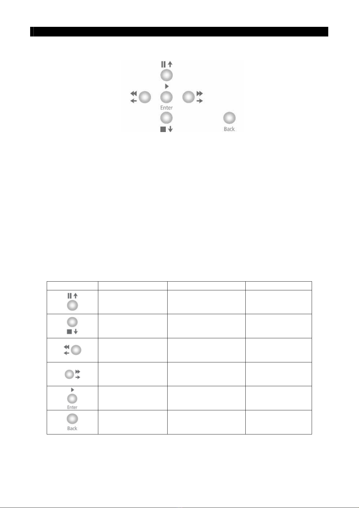
V. Menu Control Buttons / Local Playback Control Buttons / PTZ Control Buttons
In Menu Control Mode,
- The buttons are used as “Up”, “Down”, “Left”, “Right”, “Enter” and “Back” control
In Playback Control Mode,
- The functions are “Pause”, “Stop”, “Fast Backward”, “Fast Forward”, “Play” and
“Back” control
In PTZ Control Mode,
- The functions are “Up”, “Down”, “Left”, “Right”, “Zoom In”, and “Zoom Out”
control
Summary of Control Button
Buttons Menu Control Mode Playback Control Mode PTZ Control Mode
Up Pause Tilt Up
Down Stop Tilt Down
Left Rewind Pan Left
Right Forward Pan Right
Enter Play Zoom In
Back Back Zoom Out

Tele
Eye RX User Guide Page 7
Front Panel Description
VI. Mode Control Buttons and LED
- These 5 buttons are used for switching between the control modes
- “Event”button : Fast switch to event menu at any time
- “Rec”button : Enable/disable normal recording at any time
- “Live”button : View live video at any time and enable/disable PTZ in live mode
- “Search”button : Fast switch to playback log menu
- “Menu”button : Switch to menu for system settings, recording settings and event
settings etc
Notification LEDs
There are 5 notification LEDs, 2 red color and 3 blue color from left to right.
- {Event LED} : This LED will blink when event is triggered. It will be turned ON
when user press “Event” button to search event log
- {Recording LED} : This LED will be turned ON when the transmitter is recording
- {Live LED} : This LED will be turned ON when user presses “Live” button. It
indicates live mode
- {Search LED} : This LED will be turned ON when user presses the “Play” or
“Search” button. It indicates playback mode
- {Menu LED} :This LED will be turned ON when users press “Menu” button. It
indicates menu mode
VII. Power LED
- {Power LED} : This LED will be turned ON continuously when hard disk rack key
is locked and power switch is turned ON
Tele
Eye RX User Guide Page 8
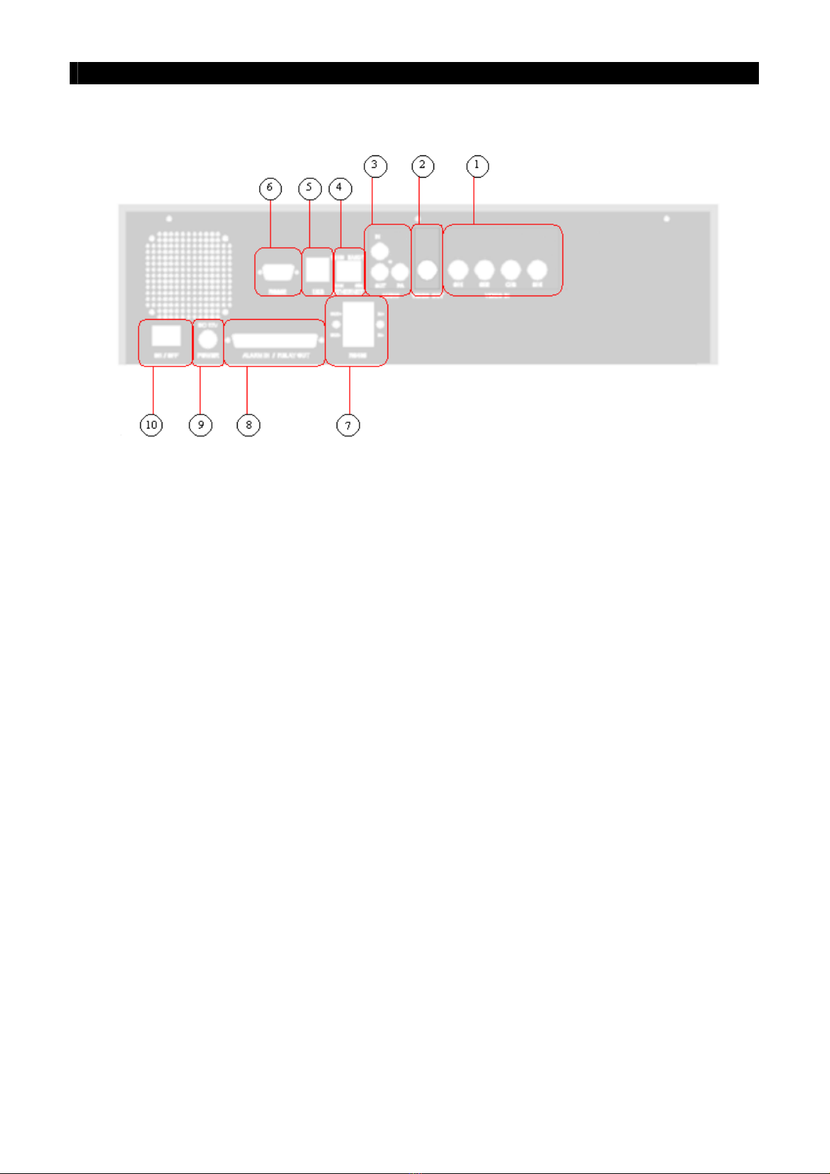
Rear Panel Description
F. Rear Panel Description
I. Video Input Connectors
- Channel 1 – Channel 4 (for
Tele
Eye RX304 only)
- {Standard BNC connectors} for video source input
- A composite video source from camera should be supplied to these connectors
II. Video Output Connector
- A composite video signal with 1V p-p is output from this connector
- Support PAL or NTSC format
- PAL/CCIR format with 625 lines, 50 fields per second
- NTSC/EIA format with 525 lines, 60 fields per second
III. Audio In/Out Port **
- {Audio In} : Connect audio input device (e.g. microphone) with RCA jack to
Tele
Eye RX transmitter for recording
- {Audio Out} : Connect audio output device (e.g. speaker) with RCA jack to
Tele
Eye
RX transmitter and generate output audio signal
- {Audio PA} : Connect audio output device (e.g. speaker) to
Tele
Eye RX transmitter
and generate audio signal as remote public addressing enable
** : This function will be supported in the
Tele
Eye RX transmitter version 2.00.00 or later.

Tele
Eye RX User Guide Page 9
Rear Panel Description
IV. Ethernet Socket (10/100 Base-T)
- This socket is used for connecting
Tele
Eye RX to the corporate computer network (e.g.
LAN)
- This socket includes {COL LED} and {LINK LED}
- {COL LED} : When ON, indicates that collision is occurring on the network
- {LINK LED} : When ON, indicates that
Tele
Eye RX is connecting to the network and
ready to function
V. USB
- For support use only
VI. RS 232 (Modem) Port
- A {DB-9 Male Connector} of DTE format, capable for connecting to DCE such as
modem, ISDN terminal adapter
Pin number Definition Direction
1 CD Input
2 RXD Input
3 TXD Output
4 DTR Output
5 GND –––
6 DSR Input
7 RTS Output
8 CTS Input
9 No use
VII. RS 485 In/Out Port
- {In} : 2-way terminal block for connecting a keyboard controller to
Tele
Eye RX
transmitter in order to control a PTZ camera
- {Out} : 2-way terminal block for connecting a PTZ camera

Tele
Eye RX User Guide Page 10
Rear Panel Description
VIII. Relay Out / Alarm In Port
- 4 relay (also call switch) ports
- 4 alarm ports
- All alarm ports are NC/NO type and none/SEOL/DEOL tamper type input
- All relay ports are latching/push-button type output
IX. Power
- Connect power supply (12V DC, 5A) to
Tele
Eye RX transmitter
X. Switch
- Switch on or off the
Tele
Eye RX transmitter

Tele
Eye RX User Guide Page 11
Hard Disk Installation
1. HDD Activity indicator
2. Power indicator
3. Active-handle
4. Handle
5. Cartridge frame
6. Key lock
2
Hard Disk Installation,
Formatting and Scanning
A. Hard Disk Installation
Tele
Eye RX transmitter supports ATA standard hard disk. User should use the hard disk listed
at the hard disk recommendation list on P.18.
Recommendation : The hard disk is recommended to set to Master Mode. How to set to
Master Mode, please refers to the hard disk case or its manual
Hard Disk Front Panel Description
Key Lock Description
SECTION

Tele
Eye RX User Guide Page 12
Hard Disk Installation
Installation Procedure
Turn OFF transmitter
Step 1: Press “Menu”button, select [SHUT DOWN] option and press “Enter”button.
Step 2: [SHUT DOWN] menu will pop up and select [SHUT DOWN] option and press “Enter”button.
Step 3: Select [YES] option and press “Enter”button to turn off the transmitter. Switch OFF the
transmitter when the [IT IS NOW SAFE TO TURN OFF RX] message pop up.
Note that you MUST turn OFF the transmitter when install or remove Hard disk.
Step 4: Pull the active-handle outwards, then use the
bundled key provided and insert into the
keyhole, turning the key anti-clockwise
(position C), then you can pull out the handle.
Step 5: Pull the handle outwards to remove the carrier
body away from the cartridge frame.
Step 6: Push the release latch to slide the top cover
backwards and remove.

Tele
Eye RX User Guide Page 13
Hard Disk Installation
Step 7: Insert the DC power cable and IDE cable on
the HDD
Step 8: Position the HDD into carrier body and secure
the HDD using the four screws provided.
Step 9: Slide the top cover back to the carrier body by
sliding forward to secure.
Step 10: Slide the carrier body back into the cartridge
frame and push carrier body further into
cartridge frame until fully inserted.
Step 11: Pull the active-handle outwards, then use the
bundled key and insert into the keyhole,
turning the key clockwise (position A) to
secure the handle.

Tele
Eye RX User Guide Page 14
Hard Disk Formatting
B. Hard Disk Formatting
Hard disk formatting will reconstruct the structure of hard disk so that it is readable by
Tele
Eye RX transmitter. If you have your own hard disk to install to
Tele
Eye RX transmitter,
you must perform hard disk formatting.
I. New Hard Disk Formatting
It will be used if the hard disk format is NOT
Tele
Eye RX transmitter recognized format.
Usually, a new hard disk, or a hard disk which has been formatted by MS Windows before
needs to do this operation.
Procedure
Step 1: After booting up
Tele
Eye RX transmitter,
OSD menu will pop up [INCORRECT
DISK FORMAT] menu. Select [YES]
option and press “Enter”button to
format new hard disk
[FORMAT DISK] message board will pop up to
show you about the status.
After finishing format process, [SCAN DISK]
processing board will pop up to show you about the
status. The transmitter will restart.
INCORRECT DISK FORMAT
FORMAT NOW ?
YES NO
SCAN DISK
\ SCANNING 90%
FORMAT DISK
\ FORMATTING 90%
This manual suits for next models
1
Table of contents
Popular Extender manuals by other brands


Sans Digital
Sans Digital EliteSTOR ES212X12 Quick installation guide

SC&T
SC&T HE01F-4K6G user manual

Rose electronics
Rose electronics CrystalLink USB3.1 Fiber Dual Port Installation and operation manual

Magenta
Magenta 2211034-02 Quick reference & setup guide

Optics
Optics M1-203D-TR user manual

Uniden
Uniden U60 4G CELLULAR BOOSTER UNI-2005-CPAL instruction manual


