TradExpertisse PODRP27 User manual

-- Wide Dual Band Booster (Model: PODRP27)
1
User Manual
User Manual
2012 February
Wide Dual Band Booster
Information in this manual is subject to change without notice
www.amplificadorcelular.com PBX (1) 231 9661 Cel 310 309 9002

-- Wide Dual Band Booster (Model: PODRP27)
2
User Manual
Table of Contents
1 Description ................................................................................ 3
2 Technical Specifications ............................................................ 4
3 System Diagram ........................................................................ 5
4 Product Features ....................................................................... 5
5 Applications Example ................................................................ 6
5.1 Minimum Signal Levels ..................................................... 8
5.2 How to check your signal levels ........................................ 8
5.3 Custom Applications ......................................................... 8
5.4 Isolation and Separation ................................................... 9
6 Production Operation ................................................................ 9
6.1 Notices .............................................................................. 9
6.2 Installation ....................................................................... 10
6.3 Commissioning ............................................................... 10
Important Notice:
Don’t power on Power supply for repeater before donor and
service antenna connects to repeater.
www.amplificadorcelular.com PBX (1) 231 9661 Cel 310 309 9002
-- Wide Dual Band Booster (Model: PODRP27)
3
User Manual
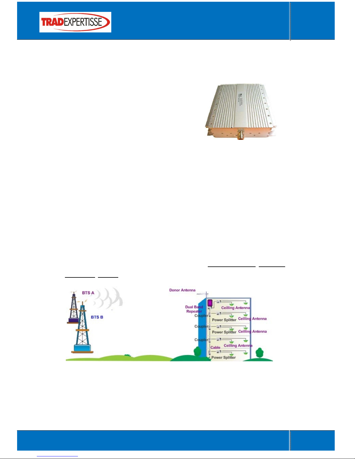
1 Description
The wide dual band booster (PODRP27) is a bi-directional amplifier used to
enhance signals between a mobile and a base
station. This repeater type is used for digital
telecommunication system:
1) -It picks up the strongest signal from
BTS via the Donor Antenna,
2) -Linearly amplifies the signal and then retransmits it via the Indoor
Signal Distribution System to the weak/blind coverage area.
3) -And the mobile signal is also amplified and retransmitted to the BTS
via the opposite direction.
It is commonly used in the area there are two type of mobile network, such as
GSM/CDMA, GSM/DCS, and GSM/UMTS. It will reduce site deployment cost
by using one dual band donor antenna, one dual band service antenna, and
dual band repeaters in one enclosure.
It is applied to small, medium-size areas such as corporation office, shop mall,
bus station, factory etc.
This model booster is commonly used in situations where large numbers of
frequency carriers are to be repeated or when base station synthesized
frequency hopping is used.
This model booster does not separate out specific carriers but amplify and
www.amplificadorcelular.com PBX (1) 231 9661 Cel 310 309 9002

-- Wide Dual Band Booster (Model: PODRP27)
4
User Manual
retransmit all signals within a defined frequency band. Inter-modulation
distortion caused by band selective repeaters usually means that lower output
power per carrier can be realized compared to channel selective repeaters.
2 Technical Specifications
Band A Band B
Network(Customized) Any two bands of 800/850/900/1800/1900/2100
Gain Uplink 65±2dB 65±2dB
Downlink 70±2dB 70±2dB
Output Power Uplink 23±2dBm 23±2dBm
Downlink 27±2dBm 27±2dBm
Gain Adjust Scope MGC≥30
Gain Adjust Step 1dB
Gain Adjust precision 0~10dB/±1dB#10~20dB/±1.5dB#20~31dB/±2dB
Band Ripple ±4
ALC Scope 20dB
Frequency Error ≤±0.05
I/O Impedance 50Ω/N connector
VSWR ≤1.5
Noise figure ≤8
Spurious Emission ≤-36dBm@9KHz~1GHz/≤-30dBm@1~12.75GHz
IM3 -40dBc
Delay ≤0.5μs
Max Input Power Level(1minute) -10dBm
RF Connector N-Type (Female)
Temperature Range Operation: -25°C ~ + 55°C;Storage: -30°C ~ +60°C
Relative humidity 5~95% RH
Power consumption 50W
Power Supply AC220V
Power Supply(Customized)
AC/110V±10% 60Hz
Power Supply Socket(Customized) Connector Type B
Weight 2.5kg
Shipment Dimensions 340×258×88mm
Shipment Weight 3kg
Indicator
Power Run - Green Light on
RF Output Power
- A/B UL Output: ON(Output power>rated output power-3dB)
- A/B DL Output: ON(Output power>rated output power-3dB)
- Alarm: Red Light on
www.amplificadorcelular.com PBX (1) 231 9661 Cel 310 309 9002

-- Wide Dual Band Booster (Model: PODRP27)
5
User Manual
3 System Diagram
The RF link (donor) towards the base station is typically fed from an
outdoor antenna while the coverage area is fed by an indoor antenna
The signal from the base station is received via the Dual band Donor
antenna, then forwarded through a Quad filter (QPX), is amplified in a
low noise amplifier (LNA), and enters the band selective amplifier
board (BSA).
The first mixer stage on the BSA amplifier board, which is controlled by
a synthesizer, converts the received frequency down to the IF
frequency. The signal is then filtered by an IF SAW band-pass filter
and amplified before it is fed to the second mixer stage, controlled by
the same synthesizer as the previous one, for converting back to the
original frequency.
The output signal from the mixer is then amplified in the power
amplifier, which is controlled by the CU(Control Unit board).The output
signal passes a Quad filter (QPX), before it is fed to the Dual band
MS antenna which retransmits the signal at the same frequency to the
aim areas.
www.amplificadorcelular.com PBX (1) 231 9661 Cel 310 309 9002
Table of contents
Other TradExpertisse Extender manuals


