MORE
THAN
JUST STEREO -
MAGNETOPHON
77
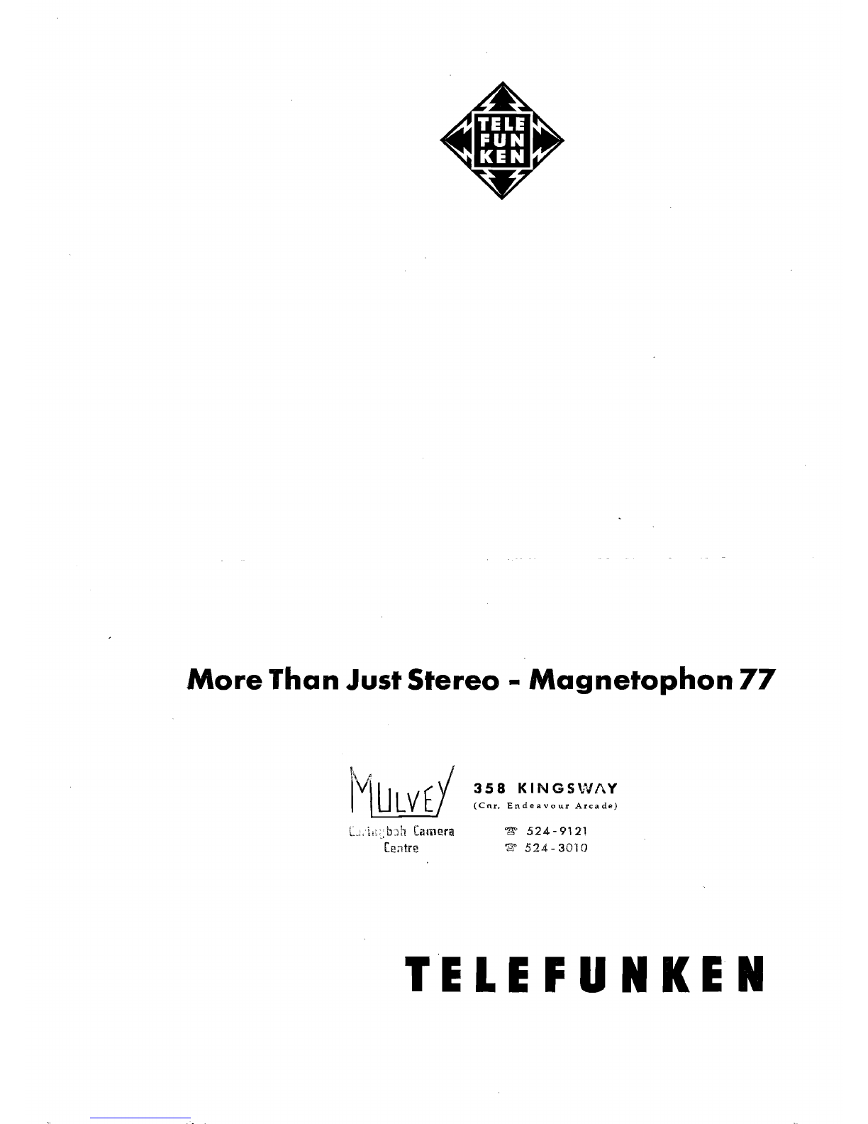
Illustration 1:
Rotating
tape
guide
roller in
Magnetophon77.
The
latest
polls,
conducted
with
the
purpose
of
determining
"the
typical
tape
recorder
buyer",
show
a
very
interesting
result.
According
to the findings
of the
poll
there
are
two
basic
groups
of
people
who
buy
tape
recorders.
1. The
«user",·
who
shows no personal
initiative
with
his machine
but
uses it
only
for
recording
any
acoustic
entertainment
offered.
That
his
ent-
husiasm
for
the
tape
recorder
rapidly
wanes,
is
substantiated
by
the
fact
that
he
generally
buys
only
two
or
three
tapes.
Due
to this lack
of
keenness,
the
fact
that
he
owns
a
tape
recorder
can
hardly
be
considered
as
having
an
exemplary
effect
among
his circle of
acquaintances.
2.
The
tape
enthusiast,
sound
collector,
tape
corres-
pondent,
amateur,
player,
do-it-yourself
man,
call
him
what
you
will.
This
is the
man
who uses
his
tape
recorder
to the
fullest
possible
extent
and
elevates it
from
a
primitive
record
keeping
machine to a
highly
sensitive
instrument
with
boundless
possibilities.
This
is the
type
of
man
who
exchanges tapes
with
his friends,· dubs
tapes
Jorslideor.home
movieprogrammes,
makes
trick
and
playback
recordings,
records
complete
plays
and
reports:
keeps an
acoustic
diary
on his
children
from
the
day
they
are
born,
mixes,
trans-'
cribcs
and
cuts.
There
were
contradictory
opinions
regarding
the
proportionate
size of these
two
groups.
Pessimists
estimated
the
proportion
of
people
belonging
to
group
2 in
the
Federal
Republic
of
Germany
at
10%.
Then,
the
TELEFUNKEN
Magnetophon
76
fourtrack
tape
recorder
appeared
on
the
scene
and
immediately
started
on a
triumphal
progress
which,
for
home
tape
recorders,
is
outstanding.
Above
all,
the
possibility,
when
playing
back one track, of
being
able to
hear
in
perfect
synchronization
a
recording
made
previously
on
another
track,
proved
to be
ideally
suited
to
so
many
purposes
-
dubb-
ing,
playback
recordings,
learning
foreign languages
-
that
the
development
engineers .
adopted
the
Magnetophon
76 as a basis
from
which to
work
on
the
creation
of a
stereophonic
parallel
type,
the
Magnetophon
77.
The
idea
was to
retain
the
versa-
tility
of the
monaural
machine in
the
stereo
model
and,
if possible, to
extend
this
versatility
still
further.
The
degree of success achieved in
this
venture
can be seen here.
If
one looks
at
the forebears of the
present
models
Magneto
phon
75, 76
and
77, one sees
from
the
whole
series,
starting
with
the single-speed
Magneto-
phon
65
and
going
on
via
the
two-speed
Magneto-
phon
65 S
and
the ensuing
Magnetophon
65 X to
the
·present
Magnetophon
75,
with
its
improved
technical
concept
yet
practically
unchanged
outer
appearance,
that
there
is such a
thing
as ageless
design.
Further,
and
this is far
more
important
to
the
buyer,
one sees
that
the
retention
of a
proven
mechanical
construction
which enables
more
than
200,000 machines to be
made
without
retooling,
re-
flects in
the
selling
price.
Elec.trical and Mechanical Construction
The
Magnetophon
77 is a
full
stereo machine.
This
means
that
it is
not
only
equipped
for
the
playback
of
professionally
pre-recorded
four-track
stereo
tapes
but
also for
making
stereo
recordings.
It
contains,
therefore,
two
complete,
separate
record/playback
amplifiers.
If
the
Magnetophon
75 was so
popular
for
its
com-
height
guides to be
made.
In this
connection,
special
pact
design
and
resulting
handiness,
how
much
more
mention
must
be
made
of the
rotating
tape
guide
will
this
popularity
apply
to the
Magnetophon
77.
roller
(Ill.
1),
unobtrusively
introduced
by
TELE-
There are,
however,
in this machine,
twice
as
many
FUNKEN
some
time
ago in the
Magnetophon
75,
electrical
components
due
to
the
presence of
two
which in the
meantime
has
proved
itself
so
well
in
the
complete
amplifier
circuits.
Magnetophon
76
and
77.
Indeed,
this
device
(Ger-
man
Federal
Republic
Patent
No.
848,271
dated
For
reasons of
both
space
and
heating,
the
tran-
28/7/1950), is one of the
little
secrets which
contri-
sistorization
of the
input
stage,
already
started
with
bute
to the
crystal
clear
tone
quality
of the
TELE-
the
Magnetophon
76, has been
taken
a
step
further.
FUNKEN
Magnetophon
tape
recorders.
The
problem
As a result, each channel comprises
two
transistors,
of
obtaining
a free
running
tape
is
not
One which is
a
twin
triode
and
the
output
tube
and
appears
as sol
ved
by
simply
ensuring
that
tape
height
is
follows:
OC
603 -
OC
603 -
ECC
83 - EL 95.
controlled.
Rather
the
reverse
is
the
case as
the
In
order
not
to lose the
advantageous
signal-to-noise
tape,
which is
not
a
rigid
body
but
an elastic mass,
ratio
gained
by
the use of
hum-free,
low-noise
tran-
begins to
vibrate
longitudinally
due to the
rigidity
sistorized
twin
pre.
amp.
stages, in
that
section
of of the
height
guides.
These
longitudinal
vibrations
the
amplifier
fitted
with
tubes,
both
ECC
83 tubes are
audible
during
playback
as
wide
side
bands
to
are
heated
with
DC.
The
magnet
for
the
rubber
originally
clear
sounds.
This
phenomenon,
known
sheathed
pressure
rollers
is also
DC
operated
in as
"rustle
effect",
is
especially
audible
with
pure
or
order
to
avoid
disturbing
hum fields in the
vicinity
almost
pure
sinusoidal
oscillations,
e. g.
whistled
of
the
recording
head.
recordings.
The
most
effective
countermeasure
to
Naturally,
the
recording
head
- as is
the
case
with
longitudinal
vibration
is to
steady
the
tape
by
all
TELEFUNKEN
tape
recorders
- is
surrounded
by
means
of a flywheel mass
located
as
near
as possible
a
double
shield
of rnurnetal,
while,
in the
record
or to
the
head.
For
this reason it has
long
been
the
playback
position,
a
mumetal
flap swings
against
the
practice
with
studio
machines, to fit a
large
flywheel
head
from
the
front
thus
completing
the
shielding. mass
between
the
recording
head
and
the
playback
head.
A
simple
experiment
will
show
that
the
small
With
the
Magnetophon
77, as
with
the
Magneto-
flywheel
mass
represented
by the
tape
guide
roller
phon
76,
special
value
is.
placed
on the free
running
in the
Magnetophon
75, 76
and
77, serves also to
of the
tape.
The
patented
TELEFUNKEN
automatic
eliminate
longitudinal
vibration.
With
the
tape
tape
tension
device
(German
Federal
Republic
running
at
1'/,
i.p.s.,
whistle
into
the
microphone
Patent
No.
840,014
dated
22/9/1950),
not
only
and,
during
playback,
hold
the
tape
guide
roller
ensures
that
tape
tension
during
rewind
is
constant-
back
with
a
match.
The
"rustle
effect"
will
be
ly
kept
below
300
gramms,
but
also,
independent
of
clearly
heard.
the
tape
diameter
of
the
LH
reel,
ensures
even
tension
along
the
entire
length
of
the
tape
which in Operation and Switch Possibilities
turn
effects
constantly
even
tape
pressure
against
the
head.
The
head
assembly
with
its
three
height
Here
too the
thoughtfulness
of the
development
guides, is
pre-assembled
as one
unit
as this system
engineer
can be
clearly
seen.
The
convenient
push-
enables
even
more
exact
adjustment
of
head
and
button
control
system,
taken
over
practically
un-
J5!.g--rphon~_--J
.JJ u,
earphone
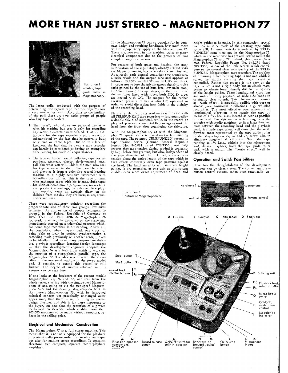
IIIustration 2:
Controls of
Magnetaphan
77. v Remote control
Rodiow
A Full reel B Counter C Tope
speed
D Empty reel
Stop
button S
button T
F,\ Ploybock track
F, J selector butto
Start
Record trock
selector buttons E Splicing rail
Micro Rodio
G switch
ON/OFF,
H modulotion
control
Modulotion
indicator
Q, Q,
po N M L K, K,
Extension
speaker
Record releose ON/OFF switch for Bockword or Quick stop Microphone
connections, button built-in
speoker
forword rewind button inputs
2x2.5W
control