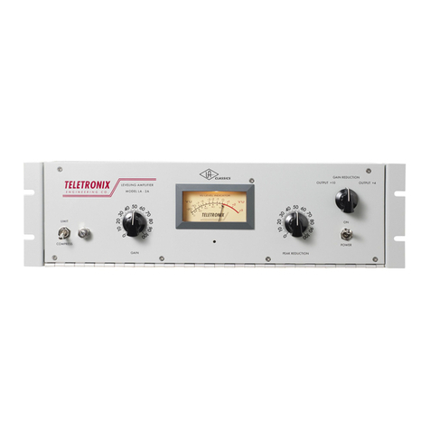
TELETRONIX LA-2A User manual

['J
]
[ ]
[ ]
[ ]
[ ]
[ ]
[ ]
[ ]
L
[ =
[ l
[
....,
[
[
[ =
[ =
[ =
l ]
l=
INSTRUCTION
MANUAL
LEVELING
AMPLIFIER
MODEL
LA-2A
TELETRONIX
DIVISION
BABCOCK
ELECTRONICS
CORP.
2952
RANDOLPH
STREET
COSTA
MESA,
CALIFORNIA
TELEPHONE
(714) 5
40-4040

LA-2A
(3-66)
0.5
to 5
seconds
for
complete
release
depending
upon
amount
of
previous
reduction
Page
2
[ J
1
E ]
[I
J
OPERATING
INSTRUCTIONS
[I
J
TELETRONIX
MODEL
LA-2A
LEVELING
AMPLIFIER
[I
J
INTRODUCTION
The
Teletronix
Leveling
Amplifier
will
automatically
reduce
audio
peaks
which
might
[I
J
otherwise
over
drive
broadcast
or
recording
equipment.
Automatic
gain
reduction
is
accomplished
by
the
use
of
an
electro-optical
variable
[rJ
attenuator,
which
is
placed
ahead
of
the
first
amplifier
stage.
The
attenuation
is
controlled
by
the
amplitude
of
the
LA-2A
input
signal.
[I
J
[I
This
system
permits
up to
40
DB
of
instantaneous
gain
reduction,
yet
causes
no
wave
form
or
harmonic
distortion.
The
amplifier
provides
sufficient
gain
and
output
level
(10 DBM
[I
nominal)
to
be
used
as
a
line
or
program
amplifier,
or
for
direct
connection
to
the
transmitter
in
the
case
of
radio
or
TV
operation.
[I
Provisions
are
made
for
interconnection
of
the
optical
attenuators
to
provide
equal
gain
reduction
in
both
channels
when
two
of
the
LA-2A
Leveling
Amplifiers
are
used
for
FM
stereo
broadcasting
.
[I
SPE
CIFICATIONS
1.
Gain
Reduction:
up to
40
DB
[I
J
[ 2.
Distortion:
less
than
0.35
%
total
harmonics
at
+10 DBM,
and
less
than
0.75
%
total
harmonics
at
[I
+16
DBM
output
3.
Response:
±0.1
DB,
30
cycles
to
15
KC
[I
4.
Noise:
75 DB
below
+10 DBM
output
level
[I
5.
Gain:
40
±1
DB
6.
Output
Level
: +10
DBM
nominal
+16 DBM
maximum
peaks
r
_I
7.
Input
Level:
+16
DBM
maximum
[ 1
~
8.
Attack
Time:
essentially
instantaneous
(10
usee)
[ 9.
Release
Time:
approximately
0.06
seconds
for
50%
release,

[;
[I
10.
Input
Impedance:
50, 150, 250,
and
600
ohms,
balanced
or
[I
unbalanced
11.
Out~ut
Impedance:
50, 150, 250,
and
600
ohms,
balanced
or
[f
unbalanced
12.
Output
Source
Impedance:
approximately
150
ohms,
at
800
CPS
[I
J 13.
Panel
Size:
standard
19" x
5-1/4"
[I
J 14.
Depth
Behind
Panel:
7-1
/
4"
15.
Panel
Controls:
Gain
(input
level),
Peak
Reduction
and
Meter
[I
Selector
Switch
16.
Meter:
DB
Gain
Reduction
and
DB
Output
[ J 17.
Power
Requirements:
115/
230
volts
50-60
cycle
35
watts
['J 18.
Tube
Complement:
( 2 ) 12AX7A
[ ( 1 ) 12BH7A
( 1 ) 6AQ5
19.
Fuse:
3AG, 3/ 8 AMP
Slow
Blow
for
115V;
[
.-
3AG 15/ 100 AMP Slow Blow
for
230V
[ -
CIRCUIT
DESCRIPTION
The
LA -
2A
Leveling
Amplifier
will
produce
essentially
instantaneous
gain
reduction
of
[
..
over
40 DB with no
increase
in
harmonic
distortion.
[ -A
typical
gain
reduction
curve
for
this
system
is
illustrated
on
Figure
1.
Compressor
action
occurs
from
the
breakaway
point
at
-30
DB
input
and
up to
-20
DB,
at
which
point
the
curve
becomes
horizontal
to
exhibit
limiting
action.
The
input
increases
an
additional
20 DB,
[ .
but
the
output
increases
less
than
1 DB.
The
leveling
amplifier
thus
combines
the
characteristics
of a
compressor
and
limiter.
A
reasonable
amount
of
care
in
gain
riding
will
restrict
normal
[ -
operation
to the
compression
region,
but
uncontrolled
output
levels
will
be
prevented
by the
limited
action
.
r•
The
heart
of
the
leveling
amplifier
is
the
electro-optical
attenuator
which
is
placed
ahead
of
the
first
amplifier
stage.
The
actual
stage
gains
and
tube
operating
parameters
are
not
varied,
permitting
the
tubes
to
operate
at
optimum
conditions
regardless
of
the
amount
of
gain
reduction.
The
optical
attenuator
consists
of a
photo
·conductive
cell,
which
is
optically
coupled
to
an
electro-luminescent
light
source.
The
electro-luminescent
device
provides
a
light
intensity
[
which
is
proportional
to
the
audio
voltage
applied
to
its
terminals.
Not
unlike
a
capacitor
in
LA-2A
(3-66)
Page
3

[
~
~
J
[ 1
~
construction,
the
electro-luminescent
lamp
consists
of a
plate
of
glass
or
plastic
coated
with a
[I
clear
conducting
material
on
one
side
and a thin
layer
of
phosphor
on
the
other
side.
A
metallic
plate
contacts
the
phosphor
coating.
As
alternating
current
is
applied
to
the
conducting
plates
[\
the
phosphors
are
excited
by
the
voltage
across
the
dielectric
and
light
is
produced
.
The
amount
of
light
depends
upon the
applied
voltage
and
frequency.
The
gain
or
level
controll
ing
element
is
[I
the
photo
·conductive
cell.
The
resistance
of the cell
decreases
with
an
increase
in
the
impinging
light.
Since
the
light
is
produced
directly
fro111
the
audio
voltage,
the
response
is
instantaneous.
[
Rectification
and
filtering
of
the
audio
to
produce
a
control
signal
are
not
necessary
as
in the
case
of
conventional
limiters.
This
system
results
in
automatic
level
control
whose
speed
of
operation
[I
J
is
limited
only
by the
response
of
the
variable
resistance
photo
cell
used
.
[' A
cell
is
selected
which
provides
minimum
attack
time,
and
a
release
time
which
requires
about
60
milliseconds
for
50%
release,
and
then
a
gradual
release
over
a
period
of 1 to
15
seconds
to
the
pOint of
complete
release.
['
J
Referring
to
Figure
2,
the
functional
block
diagram,
the
input
signal
is
applied
directly
to
the
optical
attenuator
from
the high
impedance
winding
of
the
input
transformer.
The
amount
[I
] of
attenuation
introduced
by
the
optical
attenuator
is
controlled
by
the
audio
voltage
applied
to
it
by
the
6AQ5 (V4), which
is
the
luminescent
driver
amplifier.
The
amount
of
signal
applied
to
['
J the 12AX7
(Vi)
voltage
amplifier
is
also
controlled
by
the
manual
gain
control.
The
voltage
amplifier
stage
provides
a
gain
of 40 DB.
Overall
amplifier
feedback
of
approximately
20 DB
[ ]
provides
low
distortion,
flat
response,
and
gain
stability.
The
output
stage
is
somewhat
unconventional
in
that
a
totem
pole
or
double
cathode
follower
[ J
[
is
used.
This
output
stage
can
tolerate
great
amounts
of
output
impedance
mismatch,
but
retains
low
distortion
and
flat
frequency
response.
[ -
For
stereo
broadcasting
applications,
a
portion
of
the
input
signal
is
fed
through
the
gain
reduction
control
to
the
12AX7
control
amplifier
(V3).
The
output
at
this
stage
is
applied
to the
[
..
stereo
balance
control
and
is
also
brought
out
to a
terminal
on the
chassis
.
For
stereo
operation,
this
terminal
is
connected
to
the
same
terminal
on
an
identical
amplifier
and
control
voltage
becomes
common
to both
units.
A
gain-reduction
control
voltage
generated
in
either
amplifier
will
cause
equal
gain
reduction
in
both
units.
The
control
voltage
is
applied
through
the
stereo
[
..
balance
control
R3 to
the
6AQ5
driver
amplifier.
This
stage
provides
the
necessary
voltage
to
operate
the
electro-luminescent
light
source.
OPERATION
The
LA-2A
Leveling
Amplifier
is
designed
to
prevent
an
increase
in
output
level
beyond
a
pre-determined
point,
and due to
its
unique
deSign,
functions
as
a
combined
compressor
and
limiter.
The
effect
is
illustrated
in
Figure
1.
The
point
at
which
the
compressed
curve
breaks
LA-2A
(3-66)
Page
4

J.
(.J
(J]
[.J
[I
J
[)J
[.]
[,J
[,J
[,J
f J
['l
[:J
[I
J
[1.1
[ J
[l
J
[~J
[ 'j
I
[ ;:1
[ J
['J
['
J
away
from
the
straight
"No-Gain
Reduction"
line
is
determined
by
the
setting
of
the
"Peak
Reduction"
control.
It
can
be
seen
from
the
curve
that
compression
Occurs
and
gradually
in-
creases
over
the
first
10 DB of
input
level
rise.
The
slope
of
the
curve
then
becomes
horizontal,
preventing
an
increase
of
output
level
regardless
of
input
increase.
CONTROL SETTINGS
It
is
recommended
that
the
"Peak
Reduction"
control
be
set
to
prevent
increase
in
output
level
beyond
the
100%
modulation
point.
This
setting
should
be
made
on
typical
program
material.
Setting
of
the
"Gain"
and
"Peak
Reduction"
controls
are
independent.
However,
the
"Gain"
control
should
be
set
to
provide
sufficient
output
after
the
"Peak
Reduction"
control
has
been
adj
usted.
The
"Peak
Reduction
"
control
should
be
set
for
the
desired
amount
of
gain
reduction
as
indicated
by
the
meter
.
Continuous
extreme
reduction,
such
as
20
or
30 DB,
does
tend
to
reduce
the
dynamic
range
of
music.
Maximum
benefit
is
obtained
by
running
4 to 8 DB of
compression
continuously.
This
will
usually
cause
full
limiting
to
occur
when
100
%
modulation
is
approached.
For
ease
of
control
and
to
prevent
overload
of
the
input
transformer,
sufficient
fixed
pad
should
be
placed
ahead
of
the
LA-2A
to
allow
normal
output
at
approximately
50%
setting
of
the
gain
control.
VU
METER
The
VU
Meter
serves
two
functions;
it
indicates
output
level
as
well
as
gain
reduction
directly
in DB.
When
the
meter
selector
switch
is
placed
in
the
"output"
position,
the
meter
will
indicate
output
level
across
the
600 ohm
terminals.
The
meter
is
calibrated
to
read
0
VU
or
100
%
when the
amplifier
output
is
+10 DBM
or
+4
DBM,
depending
upon
the
switch
position.
The
position
marked
"Gain
Reduction"
permits
the
meter
to
indicate
the
amount
of
gain
reduction
or
peak
limiting
directly
in DB.
During
periods
of no gain
reduction
the
pointer
will
return
to 0
VU
on
the
meter
scale.
The
pointer
is
initially
set
to
this
position
by
means
of the
screw
driver
adj
usted
control
located
on
the
left
end
of
the
front
panel.
STEREO
If
two
LA-2A
Leveling
Amplifiers
are
to be
used
in
tandem
for
stereo,
the
gain
reduction
of
each
amplifier
can
be
made
equal,
regardless
of
which
channel
is
instigating
the
limiting.
This
is
accomplished
by
interconnecting
terminals
6
and
7 of
the
LA-2A
Leveling
Amplifiers.
The
interconnecting
wire
should
not
be
over
two
feet
in
length
and
should
be
shielded,
the
ends
of
the
shield
being
connected
to the #7
terminals
(ground).
Stereo
"set-up"
is
as
follows:
1.
Connect
the
input
terminals
of
the
left
and
right
channel
LA-2A
to an
audio
oscillator.
Make
certain
that
the
amplifiers
are
connected
in
phase
to
the
generator.
LA-2A
(3-66)
Page
5
~--------------------------------------------------------,

[
[.
-,
[, A
generator
frequenc
y of
400
or
1000
cps
is
satisfactory.
Generator
output
level
should
be set to the
average
lev
el to
be
applied
in
o
peration.
[, 2.
[
Place
the
meter
sele
c
tor
switches
in the +10
or
+4
position
and
adjust
the
LA-2A
"Gain"
controls
for
equal
output.
The
"
Peak
Reduction"
controls
must
be
set
to
full
counterclockwise
or
off.
3.
Mak
e
certain
that
the
screw
driver
adj
ustment
(R3)
on
the
rear
of e
ach
unit
are
[
-,
"full
on
"
(clo
c
kwise).
Place
each
meter
selector
switch
in
the
"
Gain
Reduction"
position.
[.
4.
Advance
the
"Gain
Reduction"
control
on
the
left
channel
amplifier
until
approxi-
mately
5 DB of
reduction
is
indicated
on
the
meters.
Note
which
channel
is
[
indicatin
g
the
most
gain
reduction.
Reduce
the
setting
of R3 on
this
unit
until
both
meters
show
equal
reduction.
l 5.
The
"Gain
Redu
c
tion"
controls
c
an
now
be
placed
at
any
desired
settin
g,
keepin
g
both
knob se
ttings
equal.
Gain
Reduction
will
now
be
e
qual
on
both
channels.
L' l
[
GAIN REDUCTION
FREQUENCY
RESPONSE
CONTROL
FM
broadcasting
and
TV
aural
transmission
systems
use
audio
pre-emphasis
in
the
transmitter.
The
standard
is
17
DB
increase
in
response
at 15 KC,
the
exact
curve
being
the
result
of a
75
microsecond
network.
The
program
frequencies
in
the
vicinit
y of 15
KC
will
l
modulate
the
carrier
17
DB
more
than
frequencies
below
1 KC.
Thus,
if
the
pro
g
ram
material
contains
a
large
amount
of
high
frequencies
,
over-modulation
may
occur
if
the
levels
had
been
1
previously
adjusted
for
program
material
with
less
high
frequency
co
ntent.
An
attempt
to
alleviate
this
problem
has
been
made
by
others
in
the
form
of
level
con-
[
trolled
high
frequ
e
ncy
cutoff
filters
and
high
end
peak
clippers.
Because
the
amount
of c
ontrol
over
the
remainder
of
the
spectrum
is
limited
and
because
of
the
high
distortion
creat
ed,
such
[
devices
have
found
only
limited
application.
[
The
Teletronix
Leveling
Amplifiers
are
capable
of
at
least
30 DB of
gain
reduction
or
limitin
g
with
less
than
0.5%
harm
o
nic
distortion.
For
most
applications,
su
ch
as
AM
broad-
casting
and
recording,
the
am
o
unt
of
gain
reduction
is
a
function
of
input
level
and
is
ind
e
pendent
[\
of
frequency.
By
increasing
the
gain
reduction
at
the
higher
frequencies,
the
over-modulation
caused
1( by
the
pre-emphasis
can
be
g
reatly
reduced
or
eliminated.
While
it
is
possible
to inc
rease
the
gain
reduction
sensitivity
on
an
inverse
of
the
pre-emphasis
curve,
this
usually
results
in
an
[ -I
insufficient
lev
e
ling
on
the
low
frequencies
. The
actual
amount
of
the
limiter
pre-emphasis
must
I
be
determined
according
to
the
amount
of high
frequency
content
in
the
program
mat
e
rial
.
L -
[L
LA-2A
(3-66)
Page
6

[I]
[ ,J
[I
J
[I
J
[I
J
[I
J
['J
[ J
[ J
[ J
I
[ ,J
[I
J
[I
J
I
[ J
[I
J
['J
[.
[
[
Adjustment
of
the
gain
reduction
frequency
response
is
accomplished
by
control
R37
which
is
located
on
the
rear
of the
LA-2A.
Increasing
the
resistance
of
R37
reduces
the
amplitude
of
the
low
frequency
voltage
applied
to
the
Peak
Reduction
control,
R2.
The
high
frequency
com-
ponents
are
not
affected
because
of the
low
reac
tance
of C12.
Thus,
if
the
control
is
set
to
the
"flat"
position
the
LA-2A
will
provide
equal
gain
reduction
on
all
frequencies.
If
the
control
is
moved
away
from
the
"flat"
position,
the
leveling
will
be
greater
on
the high
frequencies.
The
actual
setting
can
be
best
determined
on
program
material
for
a
compromise
between
low
and
high
frequency
limiting.
Maximum
high
frequency
response
will
provide
approximately
10 DB
more
reduction
at
15
KC
than
at
frequencies
below
1 KC.
230
VOLT
INPUT
The
LA-2A
is
set
for
a
power
line
voltage
of 115V
when
shipped.
In
order
to
change
this
for
230
volts,
open
the
front
panel
and
make
the
following
changes:
Locate
the
vertical
solder
terminal
strip
at
the
right
hand
end
of the
chassis.
Terminal
1
is
connected
t02,
and
3
is
con-
nected
to 4
for
115V
operation
.
Remove
these
jumper
wires
and
connect
terminal
2 to 3.
This
will
allow
operation
on 230
volts
±10%, 50/ 60
cycles.
LA-2A
(3-66
)
Page
7

'(
[
[
+20
[
+15
[.
~
iIl
Q
...:l
+10
~
;;.
~
[ ]
...:l
1-<
::>
p..
+5
[1
]
::>
1-<
0
[I
J 0
['J
[I]
-5
['J
[I
J
[I]
INPUT
[I
J
[ IJ
OUTPUT
['
I
I]
[ ]
PEAK
REDUCTION
CONTROL
o
STEREO
VOLTAGE
BALANCE
AMPLIF1ER
[ J
STEREO
(J2AX7)
~
--
--------~----------------INTERCONNECTION
V3
[ 1
[ J
V
O"TPUTINCR'A~
NO
GAIN
REDUCTION
V
OUTPUT
INCREASE
/'
WlTH
GAIN
REDUCTION
V
V--
V
-35
Figure
1.
-30
-25
-20
-15
-10
-5
o
+5
INPUT
LEVEL
DBM
Typical
Gain
Reduction
Plot
for
Model
LA-2A
Leveling
Amplifier
INPUT
TRANSFORMER
REDUCTION
FREQUENCY
RESPONSE
CONTROL
OPTICAL
ATTENUATOR
T4A
VOLTAGE
AMPLIF1ER
(J2AX7)
VI
CATHODE
FOLLOWER
(12BH7)
V2
GArN
NEGATlVE
FEEDBACK
ELECTRO-
LUMINESCENT
DRIVER
(6AQ5)
V4
OUTPUT
TRANSFORMER
[ I
LA-2A
(3-66)
Figure
2.
Limiter
Block
Diagram
Page
8

,--.
,--,
,--,
,--
r-
,--
r-
:
r--'
r-
r-
r---'
~
r--;
r->
["'""\
r'
.--,
r-1
..--,
r--J
",--,
,
f I I I I I I I I I o
JUMPER
PLUG
,
PAD
OR
PRr-[MP~ASIS
IoJETWORK
un
TI,KAIOOX
R6
TBI
"L!.O
W
1M
I
,~I'
,
----
----
1/_
Nons
:
<D
FOR
230'1
CON
IIECT
ION
SEE'
MAIoJUAL.
~
~T[NT'''3Z)8
707010/
115VCD
FORT/ONS
OF
nils
50-60'"
EaUIPIoIE'NT.
(]:I
\'ALUE
~[jHTED
ro
MATW
TIA
-=-
FD~
w
nn£u
•
D6
GAIN
REDumOIJ"
REAOIW6
-=-
t
""
RJO
47K
T3
I I
l4'K
, 470K
...-;;;:0
M
,,'V'oNV\I'o!
I""
6,1
v
TO
HEATERS
~
ANO
METE
R
lA"P
R22
33K
. T2 , UTe
~
24
zrRO,w.
R4
1M
R25
~
18-f,lJ K
6.8~
TBz
OUTPUT
600
C.T
,
600
GROUND
VU
~ETER
SCHEMATIC-LEVELING AMPLIrIER
MODEL
LA-2A
..
n>'.G
7-"-6b
TELETRON
IX
DIV
OF
BIIBCOCK
ELECT
CORP
$
-1014-1
M
1Hf'UT
6{)O
zso
c:r.
250
600
Z2DK
V4
6AQSA

I
[I]
[I
J
[I
J
[IJ
[j]
[l J
[:J
[ 1J
[t J
[I
]
[I
]
[I
J
[ ]
[I
]
[
[I
J
[IJ
[
~
J
[ IJ
[ L
J
['
J
[1-
ADDENDUM
-
LA-2A
INSTRUCTION
MANUAL
All
LA-2A
Leveling
Amplifiers
after
serial
number
572
incorporate
a
leveling
slope
control
switch.
The
purpose
of
this
switch
is
to
allow
s e
lection
of
either
limiter
or
compressor
action
in
the
LA
-2A.
Referring
to
Figure
1,
page
8
the
typical
gain
reduction
curve
is
illustrated
for
limiter
operation.
Beyond
the
break
away
point
the
output
does
not
increase
with
an
increase
of
input
l e
vel,
producing
a
plot
which
is
horizontal.
When
the
switch
is
set
for
compressor
operation,
the
output
will
increase
slightly
with
increasing
input
level.
The
resulting
curve
will
have
a
slope
of
approximately
3:1,
which
me
ans
that
an
inCl'
ea
se
of
input
level
of
100%
will
cause
an
output
increase
of
30%.
This
switch
is
located
on
the
chassis
adjacent
to
the
optical
a
ttenuator
(T
4A)
soc
ke
t.
LA-2A
(11-66)
Other manuals for LA-2A
2
Table of contents
Other TELETRONIX Amplifier manuals
