MANUAL
369,
1-1
43
BASIC
TELEPRINTER
GENERAL
DESCRIPTION
CONTENTS PAGE
1. GENERAL
....................
1-1
2. DESCRIPTION
.................
1-1
3. OPTIONS
.....................
1-5
4. REFERENCES
.................
1-6
1.
GENERAL
1.01 This section provides a general descrip-
tion
of
the
43 Basic
Teleprinter
terminals
and station arrangements.
1.02
All ordering
numbers
shown in this
manual are
Teletype
Corporation
part
numbers.
2. DESCRIPTION
2.01 The
43
Keyboard Send Receive KSR
sprocket feed
station
with integrated
Terminal Data Unit (TDU) consists
of
a keyboard
printer
station
arrangement
and a
modular
500
or
2500
telephone.
The
station
connects
directly
to
the
switched
telephone
network
by means
of
a
modular
cord.
2.02 The 43 KSR and RO
Stations
are also
available with friction feed roll
paper
handling capabilities
and
an answer back circuit
card.
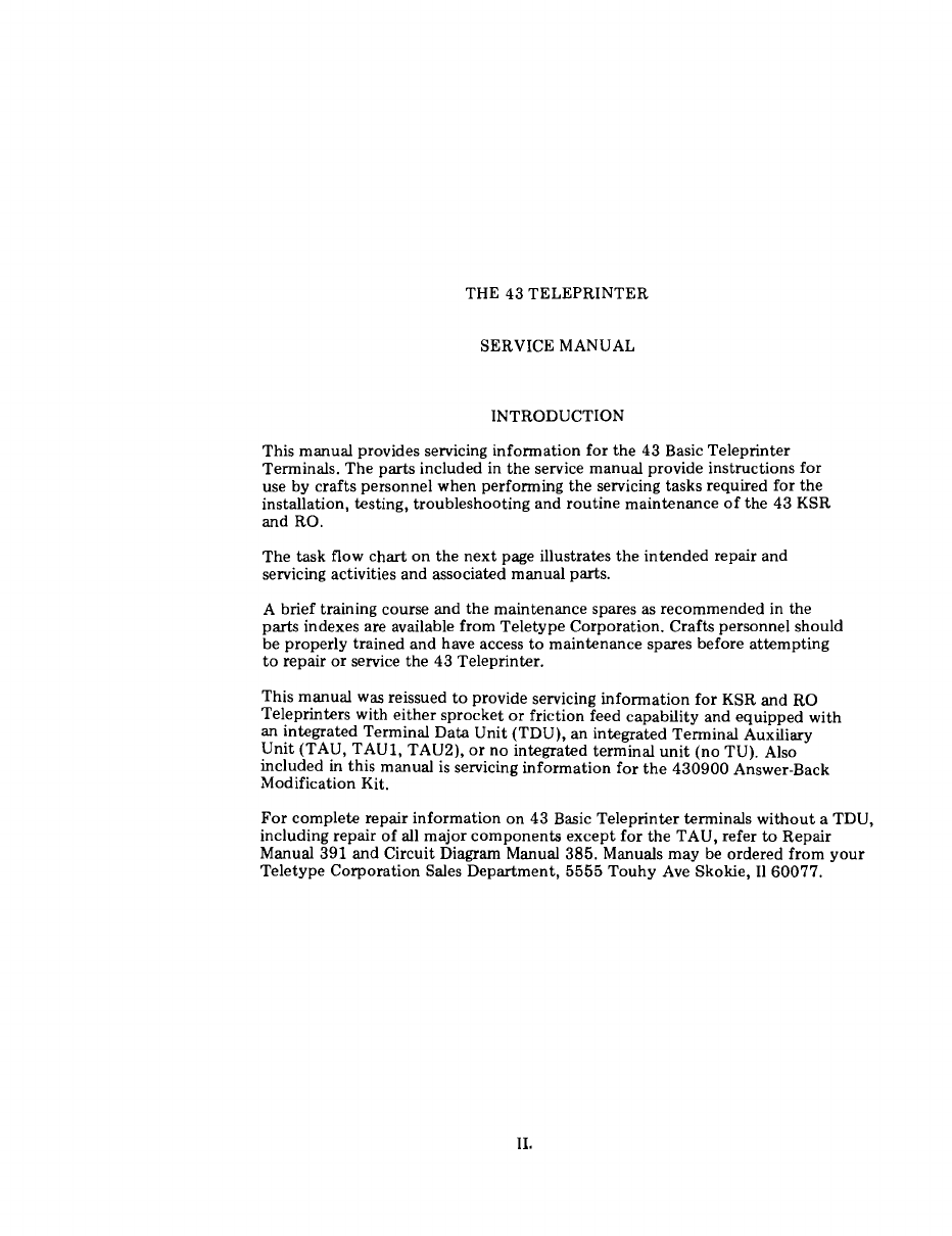
2.03 Various
43
terminal arrangements are also
available
without
a directly
connected
telephone witb
either
friction
or
sprocket
feed
paper handling as follows (See Fig. 2).
•KSR
with Terminal Auxiliary
Unit
(TAU)
that
has an EIA Interface.
•KSR
with Terminal Auxiliary
Unit
(TAUl)
that
has a single
combined
EIA/Current
inter-
face
port.
•KSR
with
Terminal Auxiliary
Unit
(TAU2)
that
has dual
combined
EIA/Current
interface
ports.
•KSR
with
no
internal
data
unit
that
has a
Transistor-Transistor Logic (TTL) voltage level
interface.
•Receive Only (RO) terminals with
either
an
internal
data
set, TAU,
TAUl,
or
no internal
data
unit.
2.04 Terminals
with
EIA interface are normally
connected
to
private lines
or
to
an external
data
set
which
is
connected
to
the
public switched
telephone
network.
2.05 Terminals with no internal
data
unit
or
current
interface are usually directly
connected
to
a nearby
data
device
or
computer.
Fig.
1-43
KSR
Sprocket
Feed
Station
TCI Library https://www.telephonecollectors.info