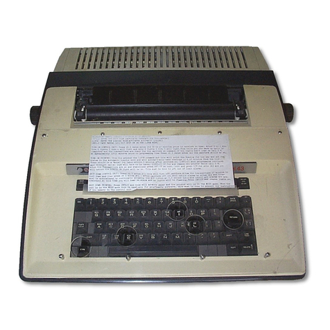
Teletype 35 User manual

BULLETIN 280B
VOL. 2
TECHNICAL MANUAL
MODEL 35
AUTOMATIC SEND-RECEIVE
TELETYPEWRITER SET
(ASR)
TELETYPE'
CORPORATION
5555 TOUHV AVENUE. SKOKIE, ILLINOIS
SEE INDIVIDUAL SECTIONS FOR COPYRIGHT NOTICES.

280B
Volume 2
INTRODUCTION
Bulletin 280B is a technical manual that provides general
and specific technical information about the Model 35 Automatic Send-
Receive Teletypewriter Set (ASR) and its component units.
The bulletin is made up of two volumes. Volume 1 contains
descriptions and principles of operation, lubrication, and disassembly
and reassembly. Volume 2 contains adjustments.
Each volume is made up of a group of appropriate inde-
pendent sections. The sections are complete within themselves; they
are separately identified by title and section number and the pages of
each section are numbered consecutively, independent of other sections.
The identifying number of a section, a 9-digit number, ap-
pears at the top of each page of the section, in the left corner of the
left-hand pages and the right corner of the right-hand pages. The
sections are placed in the manual in ascending numerical order.
To locate specific information refer to the table of contents
on the following page. Find the name of the involved component in
column one and the title of the section in column two. The correct
9-digit section number will then be found in column three. Turn to page
one of the section indicated, where the contents of that section will be
found (except where a section is small and does not require a listing
of contents).
The sections comprising this bulletin are now stocked sep-
arately and may be individually ordered if the entire bulletin is not needed.

280B
November 1968
Volume 2
Change 7
TABLE OF CONTENTS
FILING INSTRUCTIONS
1.
The following filing instructions apply to changes sent to the field.
2.
Asterisks (*) in the table of contents indicate changes.
3.
When the issue of a section changes, replace the old issue with the
attached new one.
4.
In the case of addendums, turn to the affected section and follow
the instructions on the first page of the attached addendum.
5.
Replace the old table of contents with this new one.
Equipment
Typing Unit (LP)
Keyboard (LAK)
Transmitter Distributor Base
(LCXB)
Nontyping Reperforator (LRPE)
Transmitter Distributor (LXD)
Cabinet (LAAC)
35 Reperforator Bases (LRB)
Typing Reperforator (LPR)
Answer-Back Assembly
Title
Adjustments
Adjustments
Adjustments
and Lubrication
Adjustments
Adjustments
Adjustments
Adjustments
Adjustments
Adjustments
Section
Issue
574-220-700TC
8*
574-222-700TC
5*
574-223-700TC
3
574-224-700TC
4
574-225-700TC
4*
574-228-700TC
4*
574-232-703TC
1
574-233-700TC
5*
574-235-700TC
5
Note: For information on motor units, see Bulletin 295B.

TELETYPE CORPORATION
SECTION 574-220-700TC
Skokie, Illinois, U. S. A.
Issue 8, November 1968
35 TYPING UNIT (LP)
ADJUSTMENTS
CONTENTS
PAGE
CONTENTS
PAGE
1.
GENERAL
4
Paper finger latch spring
(sprocket feed)
82
2.
BASIC UNITS
8
Paper finger shaft spring
(sprocket feed)
82
Codebar Mechanism
Paper finger spring (friction feed). .
77
Paper guide (sprocket feed)
87
Codebar detent
78
Paper pressure bail spring
Codebar detent spring
78
(friction feed)
77
Codebar shift lever
23
Paper straightener collar
Codebar shift lever drive arm
20
(friction feed)
76
Codebar yield spring
78
Paper straightener lever spring
Common transfer lever spring
21
(friction feed)
76
Intermediate arm backstop bracket. . . 22
Platen detent bail spring
68
Intermediate latch eccentric
24
Platen endplay (sprocket feed)
85
Intermediate reset bail eccentric . . . 25
Pressure roller lever spring
Intermediate reset bail spring
25
(friction feed)
77
Intermediate reset lever spring . . . . 25
Printed line (sprocket feed)
85
Transfer lever eccentric
21
Right margin with automatic
Transfer lever spring
21
carriage return-line feed ring
75
Single-double line feed stripper
Function Mechanism
bail assembly springs
74
Function bar spring
71
Sprocket pin separation
Function contact spring
72
(sprocket feed)
85
Function lever spring
71
Sprocket pin spring (sprocket feed). . . 87
Function pawl spring
71
Main Shaft and Trip Shaft
Function pawl timing contact
72
Mechanisms
Function reset bail blade
43
Antideflection plate
28
Function reset bail spring
43
Stripper blade drive cam position . .
70
Clutch drum position (except
Stripper slide bail arm
88
selector)
35
Stripper slide bail torsion spring . . . 89
Clutch latchlever spring (except
Stripper slide spring
89
selector)
26
Clutch shoe lever
34
Clutch shoe lever spring
35
Line Feed and Platen Mechanism
Clutch shoe spring
35
Left margin (sprocket feed)
84
Clutch trip lever spring
30
Line feed bar bellcrank spring
Clutch trip shaft set collars
29
(friction feed)
68
Codebar clutch cam follower
Line feed bar bellcrank spring
spring
27
(sprocket feed)
87
Codebar clutch trip lever
26
Line feed bar bumper
Function clutch trip lever
27
(six stop clutch only)
69
Function clutch trip lever trip arm. . . 28
Line feed bar release lever spring . .
68
Intermediate lever spring
30
Line feed clutch gear phasing
37
Line feed clutch trip lever
Line feed spur gear detent eccentric .
68
adjusting screw
32
Paper finger (friction feed)
77
Line feed clutch trip lever
Paper finger (sprocket feed)
86
eccentric post
32
© 1962, 1963, and 1966 by Teletype Corporation
All rights reserved
Printed in U. S. A.
Page 1

SECTION 574-220-700TC
CONTENTS
PAGE
CONTENTS
PAGE
Spacing clutch trip cam
Printing hammer stop bracket
61
follower spring
31
Printing hammer yield spring
60
Spacing clutch trip lever
30
Printing track
60
Trip shaft lever spring
26
Print suppression blocking bail
Typebox clutch trip lever
spring
81
eccentric post
33
Print suppression blocking levers . . . 80
Typebox clutch trip lever trip arm .
33
Print suppression blocking levers
spring
80
Positioning Mechanism
Print suppression mechanism
80
Bail arm assembly spring
49
Ribbon feed lever bracket
66
Decelerating slide spring
47
Ribbon feed lever spring
66
Horizontal positioning drive linkage . . 45
Ribbon lever spring
67
Horizontal positioning drive
Ribbon ratchet wheel friction
linkage spring
45
spring
66
Horizontal positioning locklever
Ribbon reverse detent
65
spring
38
Ribbon reverse detent lever spring . . 65
Horizontal shift link shock
Ribbon reverse spur gear
65
absorber spring
47
Ribbon tension spring
67
Horizontal stop slide spring
76
Stabilizing spring
54
Left vertical positioning lever
Typebox alignment
64
eccentric stud
40
Typebox carriage roller arm
Reversing slide adjusting stud
44
spring
54
Reversing slide brackets
44
Typebox clutch suppression arm. . . . 81
Reversing slide detent spring
44
Type pallet spring
61
Right vertical positioning lever
Selector Mechanism
eccentric stud
39
Rocker shaft bracket eccentric stud .
38
Marking locklever spring
17
Rocker shaft left bracket
37
Pushlever reset bail spring
18
Shift drive pawl guide bracket
49
Rangefinder knob
8
Shift drive pawl operating bail
48
Selector armature
9
Shift linkage (final)
59
Selector armature downstop (final) . .
15
Shift linkage (preliminary)
46
Selector armature downstop
Shift linkage spring
59
(preliminary)
10
Shift pawl selector link yield spring . . 50
Selector armature spring (double
Shift rocker bail spring
48
button) (final)
12
Shift rocker bar bearing bracket . . . . 46
Selector armature spring (double
Shift rocker lever
48
button) (preliminary)
12
Shift selector arm bellcrank
50
Selector armature spring (single
Typebox position (sprocket feed). . .
83
button)
11.
Vertical positioning lever spring. . . . 39
Selector cam lubricator
22
Vertical positioning locklever
41
Selector clutch drum
16
Vertical positioning locklever
Selector clutch latchlever spring. . .
18
spring
40
Selector clutch stop arm
8
Selector lever spring
16
Printing Mechanism
Selector magnet bracket
13
Selector magnet bracket (vertical
Printing arm
61
adjustment)
14
Printing carriage lower roller
54
Selector pushlever spring
16
Printing carriage position
58
Selector receiving margin
17
Printing hammer bearing stud
58
Spacing locklever spring
18
Printing hammer operating bail
Start lever spring
19
latch spring
60
Printing hammer operating bail
Spacing Mechanism
spring
60
Printing hammer operating bail
Automatic CR-LF bellcrank spring . . 62
spring (not as illustrated)
60
Carriage draw-wire rope
52
Printing hammer plunger spring. . . . 60
Carriage return latch bail
55
Page 2

ISS 8, SECTION 574-220-700TC
CONTENTS
PAGE
CONTENTS
PAGE
Carriage return latch bail spring . . . 55
Tabulator pawl horizontal adjustment . 109
Carriage return lever
56
Tabulator pawl (preliminary)
107
Carriage return spring
53
Tabulator pawl vertical adjustment
Dashpot vent screw
57
(final)
108
Left margin
62
Tabulator stops settings
110
Lower
draw-wire rope pulley bail
spring
52
Keyboard Lock Mechanism
Margin indicator lamp
79
Keyboard locklever spring
114
Oscillating rail slide position
(friction feed)
51
Local Backspace Mechanism
Right margin
63
Spacing cutout transfer bail spring. .
63
Camming bail spring
115
Space suppression bypass spring. . . . 63
Camming bail stop arm
115
Spacing feed pawl release link
spring
53
Lower Solenoid (for Applicable Units)
Spacing feed pawl spring
51
Lower solenoid
121
Spacing gear clearance
36
Solenoid spring
121
Spacing gear phasing
36
Spacing suppression bail spring . . .
73
Low Paper and Paper Out Alarm
Spacing trip lever bail cam plate. . .
42
Spacing trip lever bail spring
42
Mechanisms
Spacing trip lever spring
42
Low paper and paper out alarm
Transfer slide spring
57
(sprocket feed)
99
Paper out alarm assembly
(friction feed)
101
Paper out alarm bellcrank follower
spring (friction feed)
101
Paper out alarm sensing lever
spring (sprocket feed)
99
Paper Out Alarm Mechanism
(Friction Type) (Later Design)
Lever
100
3. VARIABLE FEATURES
Form-Out Mechanism
Form feed-out nonrepeat slide
spring
97
Form-out lever backstop
97
Nonrepeat slide
98
Solenoid lever
97
Horizontal Tabulator Mechanism
Lever spring
100
Switch
100
Cam plate stripper bail
105
Columnar tabulator stops
110
Print-Nonprint Solenoid Mechanism
Horizontal tab blocking lever
return spring
108
Contact button and solenoid pin
Horizontal tab intermediate bail
alignment
126
spring
103
Solenoid contact
122
Horizontal tab operating lever cam
Solenoid plunger
122
plate spring
105
Solenoid energized
124
Horizontal tab operating lever cam
Solenoid de-energized (suppression
plate
104
codebar marking)
125
Horizontal tab operating lever
Suppression bar return spring (for
extension link spring
102
units employing the print suppress
Horizontal tab operating lever link .
102
solenoid mechanism)
123
Horizontal tab pawl spring
108
Horizontal tab slide arm spring . . .
105
Timing Contact Mechanism
Horizontal tab spacing trip lever. . .
104
(Operated by Selector)
Right margin adjustment
106
Alignment of operating lever with
Right margin tabulator stop (with
cam
128
wide shelf)
110
"B" contact springs
127
Space suppression bypass spring. . . . 106
Contact assembly position
128
Spacing
cutout transfer bail set
Correction of
timing
130
collar
106
"M" contact springs
127
Page 3

SECTION 574-220-700TC
CONTENTS
PAGE
CONTENTS
PAGE
Operating lever spring
128
Form start gear play
116
"S" - "B" contact springs
127
Function contact spring
118
"S" - "M" contact gap
127
Indexing disc
116
Timing verification, 11.00 unit code . . 129
Line feed clutch trip lever spring . .
118
Twin "B" contact springs
127
Mounting bracket
116
Twin springs ("M" contacts)
127
Pointer
117
Switch contact pressure
117
Transmitter Control Contacts
Tabulation stop plate position
118
(Later Design)
Transmitter control switch
Contact bracket
119
(single contact type)
118
Normally open contact gap
119
Vertical tabulator bail spring
96
Switch contact pressure
119
Vertical tabulator slide retainer . . . . 116
Vertical Tabulator Mechanism
Transmitter Distributor Transfer
(For Bell System Switched
Control Contacts
Network Service)
Contact assembly bracket (final). . . . 111
Blocking arm (form-out)
94
Contact assembly bracket
Blocking arm (vertical tab)
94
(preliminary)
111
Form feed-out torsion spring
96
Normally closed contact spring
111
Form-out pawl spring
96
Normally open contact gap
111
Form start gear play
91
Normally open contact spring
111
Indexing disc
91
Transfer contact spring
111
Mounting bracket
90
Transmitter control contact gap . . . . 111
Off normal contact
Contact bracket
95
Transmitter Distributor Transfer
Follower lever
95
Control Contacts (Later Design)
Long contact spring
95
Contact assembly bracket (final). . . . 113
Short
Pointer adjustment
91
Contact assembly bracket
Transmitter control switch
(preliminary)
112
Contact bracket
92
Contact spring
112
Normally closed contact gap
93
Normally open contact gap
112
Normally closed contact spring. . . 93
Normally open contact spring
112
Transfer contact spring
112
Normally open contact gap
92
Transmitter control contact gap . . . . 113
Normally open contact spring. . .
92
Transfer contact spring
92
Vertical tab blocking lever arm .
92
Two Color Ribbon Mechanism
Vertical tab blocking lever spring
92
Contact activating lever
131
Vertical tabulator bail spring
96
Contact gap
132
Vertical tabulator slide retainer . . . . 90
Contact spring
132
Ribbon levers
131
1. GENERAL
Universal Function Bar
Coding
133/134
Upper Solenoid (for Applicable Units)
Solenoid spring
120
1.02 This section has been revised to include
Upper solenoid
120
recent engineering changes and additions,
and to rearrange the text, so as to bring the
Vertical Tabulator Mechanism
section generally up-to-date. Since this is a
Blocking lever
117
E
general revision, marginal arrows used to indi-
cate changes have been included.
Blocking lever spring
118
Form-out pawl spring
96
CAUTION: REMOVE POWER FROM SET OR
Form-out stop plate position
117
UNIT BEFORE MAKING ADJUSTMENTS.
Page 4
1.01 This section contains the specific re-
quirements and adjustments for the 35
typing unit.

ISS 8, SECTION 574-220-700TC
1.03 The adjustments in this section are ar-
ranged in a sequence that should be fol-
lowed if a complete readjustment of the unit is
undertaken. A complete adjusting procedure
should be read before attempting to make the
adjustment. After an adjustment is completed,
be sure to tighten any nuts or screws that may
have been loosened, unless otherwise instructed.
1. 04 The adjusting illustrations indicate toler-
ances, positions of moving parts, spring
tensions, and the angle at which scales should be
applied. The tools required to make adjustments
and check spring tensions are not supplied with
the equipment, but are listed in Section
570-005-800TC. Springs which do not meet the
requirements, and for which there are no ad-
justing procedures, should be discarded and
replaced by new springs.
1.05 References made to left, right, up, down,
front, rear, etc, apply to the unit in its
normal operating position as viewed from the
front.
1.06 When a requirement calls for a clutch to
be disengaged, the clutch shoe lever must
be fully latched between its trip lever and latch-
lever so that the clutch shoes release their ten-
sion on the clutch drum. When engaged, the
clutch shoe lever is unlatched and the clutch
shoes are wedged firmly against the clutch drum.
Note: When the main shaft is rotated by hand,
the clutch does not fully disengage upon reach-
ing its stop position. In order to relieve drag
and permit the main shaft to rotate freely,
apply pressure on the lug of the clutch disc
with a screwdriver to cause it to engage its
latch lever and fully disengage the clutch.
1.07 To manually operate the typing unit
proceed as follows.
(a)
Attach the TP312709 armature clip to the
selector magnet armature by carefully
placing the spring loop over the magnet ter-
minal insulator. Press down to engage the
hook of the clip on the underside of the arma-
ture and release. The spring tension of the
armature clip will hold the selector arma-
ture in the marking (attracted) position.
(b)
While holding the selector magnet arma-
ture operated by means of the armature
clip, use the handwheel, included with the
special tools for servicing 28 teletypewriter
apparatus, to manually rotate the main shaft
in a counterclockwise direction until all the
clutches are brought to their disengaged
position.
(c)
Fully disengage all clutches in accord-
ance with 1.06, Note.
(d)
Release the selector magnet armature
momentarily to permit the selector
clutch to engage.
(e)
Rotate the main shaft slowly until all the
pushlevers have fallen to the left of their
selecting levers.
(f)
Strip the pushlevers from their selector
levers, which are spacing in the code
combination of the character function that is
being selected, and allow the pushlevers to
move to the right.
(g)
The pushlevers and the selector levers
move in succession starting with the no. 1
to the no. 7; the no. 8 is always marking and
is not equipped with a selector lever.
(h)
Continue to rotate the main shaft until all
operations initiated by the selector action
clear through the unit.
1.08 Where adjustment instructions call for
removal of components, assemblies,
subassemblies or parts, all adjustments which
the removal of these parts might facilitate should
be made before the parts are replaced or as the
equipment is reassembled. When a part mounted
on shims is removed, the number of shims and
their location should be noted so that the iden-
tical pile-up can be made when the part is re-
placed.
1.09 All electrical contact points should meet
squarely. Contacts with the same dia-
meter should not be out of alignment more than
25 percent of the contact diameter. Check con-
tacts for pitting and corrosion and clean or bur-
nish them before making specified adjustment or
tolerance measurement. Avoid sharp kinks or
bends in the contact springs.
CAUTION: KEEP ALL ELECTRICAL CON-
TACTS FREE OF OIL AND GREASE.
1. 10 When making a complete adjustment of
the unit, the following conditioning op-
erations should be performed to prevent damage.
(a) Loosen the shift lever drive arm clamp
screw (2.13).
Page 5
SECTION 574-220-700TC
(b)
Move the right and left vertical position-
(h) Loosen the reversing slide adjusting stud
ing lever eccentric studs (2.32 and 2.33)
(2.37).
in rocker shaft brackets to their lowest
position.
(i) Loosen clamp and pivot screws on shift
arm bearing bracket and move to ex-
(c) Loosen the two bearing stud mounting
treme downward position (2.39).
screws and the two connecting strip
(j ) Loosen the clamp screw on the shift drive
clamp screws in the horizontal positioning
drive linkage (2.38).
pawl operating bail (2.41).
(k) Check the following adjustments during
(d)
Loosen the clamp screws and move the
each lubricating period.
reversing slide brackets to their upper-
most position (2.37).
(1) Printing carriage position (2.51).
(e) Loosen the function reset bail blade
(2) Printing hammer bearing stud (2.51).
mounting screws (2.36).
(3) Printing hammer stop bracket. Also
see Note in 2.54.
(f)
Loosen the carriage return lever clamp
screw (2.49).
(4) Lower draw wire rope (2.45).
(g)
Loosen the clamp screws in the oscilla-
(5) Dashpot vent screw adjustment and
ting rail slide (2.44).
check transfer slide for binds (2.50).
Page 6

ISS 8, SECTION 574-220-700TC
Figure 1 - 35 Typing Unit (Friction Feed)
Figure 2 - 35 Typing Unit (Sprocket Feed)
Page 7

MOUNTING
NUT
SECTION 574-220-700TC
2. BASIC UNITS
2.01 Selector Mechanism
(A) RANGEFINDER KNOB
Requirement
With rangefinder knob turned to either end of rack, and inner teeth of knob and teeth of
sector assembly engaged, ft mark on scale should be within ±3 divisions of scribed line
on rangefinder plate.
To Adjust
Loosen knob mounting nut and engage teeth of sector in position that most closely aligns
the mark on the plate with the (t mark on the knob.
RANGEFINDER KNOB
RANGE SCALE
RACK
CLUTCH SHOE LEVER
SELECTOR CLUTCH
CLUTCH STOP ARM
(Right Side View)
CLAMP SCREW
TRIP LEVER BAIL
(B)
SELECTOR CLUTCH STOP ARM "
iiiA
AA/vv
vv._
Requirement
Range scale set at 60. Selector clutch disengaged. Armature in marking position.
Clutch
stop arm should engage clutch shoe lever by approximately
full thickness of clutch stop arm.
To
Adjust
•
Position stop arm on trip lever bail with clamp screw loosened.
Page 8

ADJUSTING NUT
PIVOT EDGE
SELECTOR ARMATURE
Note: This requirement need
not be made nor checked if
the selector magnet bracket
and receiving margin re-
quirements are met.
(1) Requirement (Armature
Clamp Strip)
Clearance between
armature clamp strip
and casting
Min 0.010 inch
ARMATURE
(Right Side View)
1
1
CLAMP STRIP
ARMATURE
MOUNTING SCREWS
(2) Requirement (Armature
Alignment)
Outer edge of armature
should be flush within
13
ISS 8, SECTION 574-220-700TC
2.02 Selector Mechanism (continued)
Note: To facilitate making the following adjustments, remove the rangefinder and selector
magnet assemblies. To insure better operation, pull a piece of bond paper between the
armature and the pole pieces to remove any oil or foreign matter that may be present. Make
certain that no lint or pieces of paper remain between the pole pieces and armature.
To Adjust
Position armature
spring adjusting nut to
hold armature firmly
against pivot edge of
casting.
POLE PIECE
Max 0.015 inch
& U
with outer edge of pole
pieces.
ARMATURE
To Adjust
Position armature and
backstop with mounting
(Front View)
screws loosened.
Page 9

DOWNSTOP BRACKET
MOUNTING SCREW
t
I
1
POLE PIECE
t-
GAUGE
ARMATURE
ARMATURE
DOWNSTOP
BRACKET
DOWNSTOP BUTTON
SECTION 574-220-700TC
2.03 Selector Mechanism (continued)
Note: Replace rangefinder and selector magnet assembly.
SELECTOR ARMATURE DOWNSTOP (PRELIMINARY)
Requirement
Magnet de-energized. Locklevers on high part
of cam. With armature resting against downstop
Min 0.030 inch---Max 0.035 inch
clearance between end of armature and left
edge of left pole piece.
(Right Side View)
t ,
r
1-
\
--
"
-
- - -
I, . T1 ,,
-
-ir
•
To Adjust
Position downstop with downstop bracket
mounting screw friction tight.
(Front View)
Page 10

CAM
START LEVER
SPACING LOCKLEVER
(Right Side View)
ADJUSTING
NUT
ARMATURE SPRING
tat,
ARMATURE
ARMATURE EXTENSION
MARKING LOCKLEVER
Page 11
ISS 8, SECTION 574-220-700TC
2.04 Selector Mechanism (continued)
SELECTOR ARMATURE SPRING
(For Units Employing Selector Armature With Single Antifreeze Button Only)
Requirement (Preliminary)
With locklevers and start lever on high part of their cams, scale applied as nearly vertical
as possible under end of armature extension. It should require the following tensions to
move armature to marking position:
(
0.060 ampere — Min 2-1/2 oz---Max 3 oz
0.030 ampere — Min 1-1/2 oz---Max 2 oz
Note: This spring can be adjusted for maximum selector performance only when printer
is connected to the specific circuit over which it is to operate under service conditions.
Since there are several operating speeds and since circuits vary widely, it is impossible
to adjust spring for maximum performance at the factory. The foregoing spring tension
requirement is given to permit opeiation prior to measurement of receiving margins.
Readjustment made to obtain satisfactory receiving margin should not be disturbed in
order to meet requirements of this adjustment.
To Adjust
Position adjusting nut.
Requirement (Final)
See SELECTOR RECEIVING MARGIN adjustment (2.10).
0.500 ampere — Min 4-1/2 oz---Max 5-1/2 oz

GRAM
SCALE
ARMATURE
EXTENSION
ARMATURE REAR BUTTON
FRONT BUTTON
-
"
--
"*"•41111110.
ARMATURE SPRING
ARMATURE
EXTENSIONEXTENSION
ARMATURE
REAR BUTTON
(Right Side View)
SECTION 574-220-700TC
2.05 Selector Mechanism (continued)
SELECTOR ARMATURE SPRING (PRELIMINARY)
(For Units Employing Selector Armature With Two Antifreeze Buttons Only)
Requirement
With locklevers and start lever on high part of their cams, gram scale applied under end of
armature extension,
it should require approximately the following tensions to move the
rear antifreeze button against the magnet core:
[
0.020 ampere — 14 grams
0.030 ampere -- 18 grams
0.060 ampere -- 21 grams
0.500 ampere -- 28 grams
To Adjust
Position adjusting nut.
ARMATURE SPRING
(Right Side View)
SELECTOR ARMATURE SPRING (FINAL)
Requirement
When a Distortion Test Set is available, the selector
armature spring tension should be refined, if necessary,
to obtain satisfactory receiving margins. The front
antifreeze button must contact the magnet core when the
magnet coils are energized.—
(See SELECTOR RECEIVING MARGIN
adjustment, 2.10. )
FRONT BUTTON
Page 12

-r
v-
ARMATURE
ISS 8, SECTION 574-220-700TC
2.06 Selector Mechanism (continued)
MOUNTING SCREW
MAGNET BRACKET
(Right Side View)
POLE PIECE
MOUNTING1
SCREW
LINK CLAMP SCREW
ADJUSTING LINK
Note: Appropriate preliminary
selector armature spring tension
adjustment must be made before
the following adjustment.
ARMATURE EXTENSION
SELECTOR MAGNET BRACKET
(1) Requirement (For Units Employing Either One or
Two Antifreeze Buttons)
Spacing locklever on each peak of cam. Arma-
ture in contact with front pole piece (magnet
energized). Clearance between end of armature
extension and shoulder on spacing locklever.
Min 0.020 inch---Max 0.035 inch
To Adjust
Loosen two magnet bracket mounting screws
SPACING LOCKLEVER
and adjusting link clamp screw. Position
magnet bracket by means of adjusting link and
(Right Side View)
tighten link clamp screw only.
(2) Requirement
Armature in contact with front pole piece (magnet energized). Clearance between
upper surface of armature extension and lower surface of spacing locklever when
locklever is held downward.
Min some---Max 0.003 inch
To Adjust
Position upper end of magnet bracket. Tighten
two magnet bracket mounting screws.
Recheck Requirement (1).
Page 13

Ii
SELECTOR
MAGNET
ADJUSTING LINK
PRY POINT
MAGNET BRACKET
MOUNTING SCREW
'
r
-
fr
I
41
1
(Right Side View)
ARMATURE EXTENSION
MARKING LOCKLEVER
To Adjust
With mounting screw loosened
position upper end of magnet
bracket by means of pry point.
Recheck Requirements (1) and
(2) of SELECTOR MAGNET
BRACKET (2.06).
(Right Side View)
SECTION 574-220-700TC
2.07 Selector Mechanism (continued)
SELECTOR MAGNET BRACKET (VERTICAL ADJUSTMENT)
Requirement (For Units Employing Either One or Two
Antifreeze Buttons)
-Marking locklever on low of cam. Armature in contact
with left pole piece (magnet energized). There should
be some clearance between lower surface of armature
extension and upper surface of marking locklever.
Gauge by eye.
POLE PIECE
Page 14

Requirement
Magnet de-energized. Locklevers on
low part of their cams
Min 0.005 inch---Max 0.015 inch
clearance between top of armature
extension and bottom of spacing lock-
lever.
To Adjust
Refine SELECTOR ARMATURE
DOWNSTOP (PRELIMINARY) (2.03).
POLE
PIECE
DOWNSTOP
BRACKET
MOUNTING
SCREW
1Wr
MARKING
LOCKLEVER
SPACING LOCKLEVER
(Right Side View)
LOW PART OF CAM
Page 15
ISS
8, SECTION 574-220-700TC
2.08 Selector Mechanism (continued)
SELECTOR ARMATURE DOWNSTOP
(FINAL)

SELECTOR LEVER
SELECTOR PUSHLEVER SPRING
Requirement
Pushlever in spacing position
Min 3/4 oz---Max 1-1/2 oz
RESET BAIL
to move pushlevers from selector
levers on all except first pushlever
in sequence of selection. It should
require
Min 2 oz---Max 3 oz
to move this pushlever from its
selector lever. This spring is
copper color.
PUSHLEVER
(Right Side View)
SELECTOR
LEVER-0
SELECTOR LEVER SPRING
Requirement
Typing unit upside down.
Reset bail on peak of its cam.
Min 1-1/2 oz---Max 3 oz
SELECTOR CLUTCH DRUM
Requirement
Clutch latched in stop position. Cam-
clutch assembly should have some endplay
Max 0.010 inch
To Adjust
Position the clutch drum on main shaft
with mounting screw loosened. Tighten screw.
R.•
to start each lever moving.
If necessary, unhook start lever
spring to check selector lever
springs near the start lever spring.
MOUNTING
SCREW
N
MAIN
SHAFT
TRIP
7
T
tir
4
T
2
STRIP 6 LOCK 3
CAM ARRANGEMENT
(Front View)
MAIN SHAFT
4-
8
-
t
START
CLUTCH DRUM
Page 16
SECTION 574-220-700TC
2.09 Selector Mechanism (continued)

ISS 8, SECTION 574-220-700TC
2.10 Selector Mechanism (continued)
MARKING LOCKLEVER SPRING
Requirement
Rubout combination selected,
main shaft rotated until selec-
tor clutch is disengaged. Push
scale applied to lower extension
of locklever.
Min 2 oz---Max 4 oz
to start lever moving.
MARKING LOCKLEVER
SELECTOR RECEIVING MARGIN
(1)
Requirement (For Units Employing Armature With One Antifreeze Button)
When a signal Distortion Test Set is used for determining the receiving margins of the
selector, and where the condition of the components is equivalent to that of new equipment,
the range and distortion tolerances below should be met.
(2)
Requirement (For Units Employing Armature With Two Antifreeze Buttons)
When a Distortion Test Set is available, the selector armature spring tension should
be refined, if necessary, to obtain satisfactory receiving margins. The front anti-
freeze button must contact the magnet core when the magnet coils are energized.
To Adjust
Refine the SELECTOR ARMATURE SPRING adjustments
(2.04, 2.05).
Selector Receiving Margin Minimum Requirements
Speed
Points Range
End Distortion Toler-
in
With Zero
Percentage of Mark-
ated With Scale at Bias
Current
WPM
Distortion
ing and Spacing Bias
Optimum Setting
0.500 Amp
(Windings
100
72
38
35
Parallel)
0.060 Amp
(Windings
Parallel)
100
72
35
33
(For LP821
Only)
Page 17
MARKING LOCK-
LEVER SPRING
(Right Side View)
Other manuals for 35
1
Table of contents
Other Teletype Typewriter manuals