TeleVue GIBRALTAR HD4 User manual

32 Elkay Dr., Chester, New York 10918 (845) 469-4551 televue.com
TeleVue
Visionary
®
GIBRALTAR™HD5/4 MOUNT & HEAD INSTRUCTIONS
Included Parts
•Head: Gibraltar HD5 or HD4 Head with stud (Sky Tour version has altitude and azimuth encoders.)
•Head Small-Parts: see image right. •Mount: Wood Tripod •Wood Tray
Introduction
Gibraltar™ HD5 and HD4 are alt-azimuth mounts designed for Tele Vue’s 5” refractors (e.g,
NP127is) and 4” and smaller refractors (e.g. NP101is, & TV-85), respectively. We recommend the
Sky Tour Computer and Eyepiece Caddy Set for maximum viewing pleasure.
The Gibraltar HD Mount Heads cradle the telescope at its center of gravity to make operation smooth
and easy. To achieve smoothest operation it is important to have the telescope properly balanced in its
mount ring and the altitude and azimuth tension knobs providing minimal drag.
The tripod legs can position the cradle height from 3.5- to 5-feet. The triangular accessory tray adds
extra stability to the tripod.
Gibraltar HD mounts are ideal, travel-friendly, mounts for quick, convenient terrestrial and astronomi-
cal viewing, even at 200+ power.
WARNING: Do not remove the mount head and half-pillar without first removing the telescope. Fail-
ure to remove the telescope will cause the telescope, half-pillar, and mount head to fall off the mount.
Tripod Setup
Please refer to the diagrams for part nomenclature.
• Remove tripod from box. If setting up on soil, twist the rubber tips at the bottom of each leg
up to fully expose the metal spikes. On nished or hard surfaces, twist the rubber tips down to
fully cover the metal spikes.
• Use the leg-spread tension-levers, attached to the mount base, to adjust tension on the
legs to allow them to spread out slightly. Levers can be repositioned by pulling away from
legs and rotating. Place the tripod standing on a level surface. Leave the legs un-extended.
• Make sure the safety chain is attached to each tripod leg (see Additional Notes). Loos-
en the leg-extension lock knob on each leg and raise the tripod to the desired height. Then
lock the knobs. You can use the index marks on the legs to ensure even extension. Next,
spread the legs out to the limit of the chain.
• Remove the triangle tripod tray from its box. The corners of the tray have a half-clamp
that snaps onto a roll pin installed on each leg’s tray bracket. Place the tray between the legs
of the tripod and put the half-clamp from one corner above one of the roll pins. Press down
over the half-clamp to snap it into place. Snap the other two sides of the tray onto the roll
pins, in the same manner, pulling the tripod legs in as necessary. Removal of the tray is ac-
complished by pushing up at each corner of the tray from below -- where it attaches to each
roll pin.
• At the tripod base, tighten each leg-spread tension-lever to keep the mount from wobbling.
• Check the bubble level on the tripod base to see if it is close to level – it doesn’t have to be perfect – just suf-
ciently levelled so the telescope swings smoothly in any azimuth (left-right) orientation. If leveling is required, it is easiest
to collapse a leg than to extend one. Holding the leg with one hand, loosen the leg-extension lock-knob just enough so
you can draw the leg up with the other hand.
Mount-Head Install
• Inside the mount head box, locate the mount head with attached threaded stud, half-
pillar (cylinder), and half-pillar end-cap (disk with hole). Note that the pillar end-cap has a at
side and a side with a grooved edge.
• The tripod comes with an end-cap, at side down, on top of the mount base. The stud
coupling nut rests on top of this. Place the half-pillar on top of the end-cap resting on the
mount base. The other top end-cap, is already locked onto the bottom of the baseplate.
Lower the mount head so the stud makes contact with the coupling nut. With one hand, hold
the mount’s yoke baseplate while twisting the star lock knob, below the base, at the end of
the threaded rod with the other hand. This will pull the mount head down onto the half-pillar
and form a solid connection, when locked.
• Adjust the azimuth tension knob until there is a slight amount of tension. Place the cradle
in approximately level position as indicated by the altitude alignment marks (drilled hole on
one of the side altitude bearings, forming two semi-circles). Tighten the vertical tension knobs.
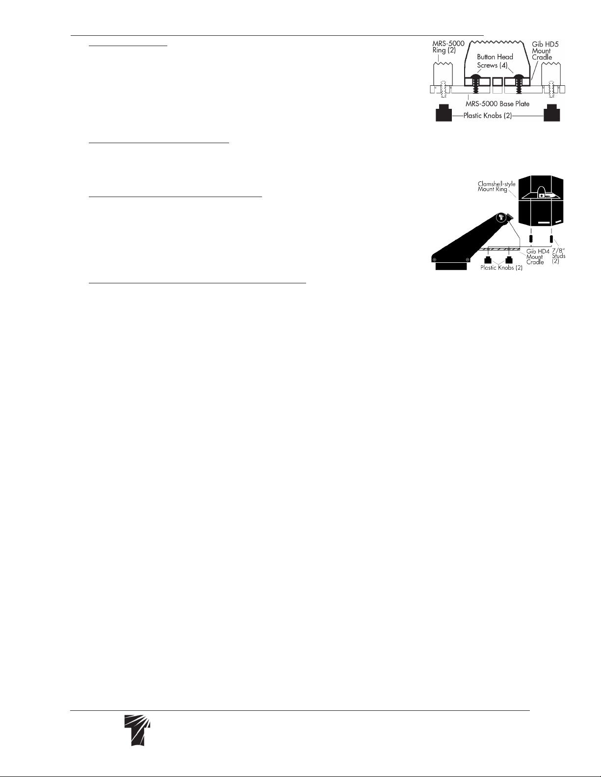
Telescope Install on Gib HD5
• Tele Vue’s 5” scopes with 5” Mount Ring Set MRS-5000. Unscrew the bat handles sup-
plied with the Ring Set to remove the top rings and plate. Fasten base plate with bottom rings
to the underside of the mount cradle using the four ¼-20 button head screws supplied. Level
the cradle and tighten the vertical tension knobs. Place the scope into the bottom rings. Replace the top-half of the Ring
Set and reinstall the bat handles to secure the scope.
32 Elkay Dr., Chester, New York 10918 (845) 469-4551 televue.com
TeleVue
Visionary
®
• Tele Vue’s 4” scopes. Because the cradle on the Gibraltar HD5 is deeper than on the
HD4, a 4” scope must be raised in the cradle for proper altitude balance. The scope is
properly balanced in altitude when the center of the tube lines up with the Gibraltar HD
sticker on the vertical axis. If your scope uses our 4” Mount Ring Set MRS-4011, attach
its bottom-plate on the top of the mount cradle using the four ¼-20 button head screws
supplied. If using our 4” clamshell-style ring, employ our Mounting Adapters BPL-1098 or
AVT-1011 between the clamshell and mount cradle to raise the scope. This last congura-
tion requires 1½” studs or similar ¼”-20 hardware (not supplied) to pass through the mount
cradle, mounting adapter plates, and thread into the clamshell.
• Mounting other Tele Vue Telescopes. If you have MRS-5000 rings, leave the base plate, without rings, attached to
the cradle. Thread the supplied longer 1¼" studs into the telescope's ring mount. (If you do not own MRS-5000 rings,
use the shorter 7/8" long studs.) Place the telescope down in the cradle so the studs go through the cradle holes. Fas-
ten in place with plastic knobs.
Telescope Install on Gib HD4
• Tele Vue’s 4” scopes with clamshell-style ring. Start with the clamshell attached to the
telescope. Make sure the bat handle and socket head screws on the clamshell are secured
to prevent the telescope from sliding. Using the 1/8” Allen key, screw the 7/8" studs pro-
vided into the 2 outer holes of the bottom half of the clamshell until they stop. (Be careful not
to overtighten: clamshell is aluminum and threads may strip from excessive force multiplied
by the leverage of the Allen wrench.) Place the telescope down into the mount’s cradle, so
that the studs pass through the holes in the cradle base. Orient the scope so the vertical ten-
sion knobs are closer to the telescope’s eyepiece end. Fasten in place with plastic knobs.
• Tele Vue’s 4” scopes with 4” Mount Ring Set MRS-4011. Unscrew the bat handles and
socket head screws supplied with the Ring Set to remove the top rings and plate. Fasten
base plate with bottom rings to the top of the mount cradle using the four ¼-20 button head screws supplied. Level the
cradle and tighten the vertical tension knobs. Place the scope into the bottom rings. Replace the top-half of the Ring Set
and reinstall the bat handles and socket heads to secure the scope.
Balance and Use
• When mounting scope, orient tube so Vertical Tension Knobs are closer to the telescope's eyepiece end.
• Put a diagonal and eyepiece on the drawtube before balancing. Adjust vertical tension knobs so they have slight
and equal tension.
• Swing the scope up approximately 45°. If the scope wants to swing up or down, level the scope and loosen the
bat handles on one side of the ring. If the scope wants to swing back down, slide the scope backwards in the mount
ring toward the vertical tension knobs. If the scope wants to swing up, push it forward so there is less tube between the
mount ring and diagonal. Recheck balance and re-tighten the bat handles when balance is achieved.
• Check the tension on the azimuth tension knob so the mount rotates smoothly. WARNING: Rotating the mount
head while the azimuth tension knob is tightened could cause the azimuth bearing to unscrew and separate.
• Extra tension can be used to overcome a minor out-of-balance condition. However, excessive tension will cause
the movement to be “jerky.” Severe overtightening could strip the threads in the mount head.
• The most stable way of slewing your scope is by grasping a xed part of the telescope, (i.e., focuser body), mount
head or (optional Gib HD4) mount handle. Slewing the scope by holding the diagonal could cause slight image shift.
Additional Notes
• The safety chain is a safety device to prevent the legs from overspreading or collapsing when setting up the tripod
for observing. It should remain on at all times. If the chain needs to be re-attached, slip each snap hook on the chain
onto an eyelet on the inside of the leg-extension lock-knob brackets.
• Gibraltar HD heads can be moved to a heavy-duty camera tripod by removing the mount stud. Use 5/64” Allen
to loosen lower set screw on Azimuth bearing plate, and then unscrew the stud. Normally this set screw is tight to pre-
vent stud from unscrewing from the head as mount is turned in azimuth.
Storage
• Before storing, if dew is present on the tripod, wipe it with an absorbent cloth and allow to dry for about 24 hours at
room temperature. Do not place the tripod close to any direct source of heat as this will cause the wood to dry out unevenly.
• If the tripod is set up and left standing in a low humidity room over a lengthy period of time, check the leg-extension
lock knobs, and tighten them if necessary to prevent the tripod legs from collapsing.
• Each time you remove the tripod head, with attached top end-cap, the half pillar is unsupported and must be removed.
Upon removal, make sure the stud coupling nut is threaded all the way down on the threaded rod and the setscrew on the
side of the nut is secured to prevent the nut from turning. If the coupling nut is loose, or removed, attach it as follows: use a
5/64” Allen key to back out the setscrew so the coupling nut can thread freely on the rod. With one hand below the tripod
base, push the star lock knob up so the threaded rod passes through the half-pillar end cap. With the other hand, place the
stud coupling nut, with the set-screw end facing down, onto the top of the threaded rod. Spin the star lock knob so it threads
onto the stud coupling nut. The coupling nut will move down the top threaded part of the rod, pass through reduced shank
and stop at the full shank on the other side. This should leave about ½” of available thread on the top of the coupling nut.
Now tighten the setscrew on the side of the coupling nut with the 5/64” Allen key to prevent it from coming loose.
• When storing the scope in a case with the mount rings and studs attached, screw the plastic knobs onto the studs to
prevent ripping the foam liner.
Gib HD5 Head
Gib HD4 Head
This manual suits for next models
1
Table of contents
Other TeleVue Camera Accessories manuals

Popular Camera Accessories manuals by other brands


Vivitar
Vivitar VIVITAR VIV-PG-50D instruction manual

GRASS VALLEY
GRASS VALLEY EYECATCHER EC270 Service manual

Energizer
Energizer NH12-1000 Product data sheet

Pentax
Pentax Auto 110 Winder user manual

Honeywell
Honeywell Acuix IP Series installation guide

Antigravity Batteries
Antigravity Batteries VTX20 user manual