TeleVue NP101is User manual
32 Elkay Dr., Chester, New York 10918 (845) 469-4551. televue.com
TeleVue
®
Visionary
540mm f/5.4 IMAGING SYSTEM
4-ELEMENT APO REFRACTOR
Thank you for purchasing the Tele Vue-NP101is. It has been our pleasure to craft this fine instrument for
you. Over forty years ago, Al Nagler took Petzval’s portrait lens concept using widely spaced doublets,
and patented a fast telescope design version for the purpose of testing eyepieces. The 5” f/4 MPT (Multi-
Purpose Telescope) with its fast speed, wide and flat field, led to a series of continuous improvements,
primarily in color correction. The “Halley Commemorative,” 4” f/5.5 Renaissance started the parade
where more advanced glasses including special dispersion, fluorite and fluorite substitute glasses brought
steady improvements. The 4” f/5 Genesis employed fluorite in the rear doublet and the f/5.4 SDF and
subsequent Tele Vue-101 versions brought us closer to perfection. Maintaining the f/5.4 speed while
reducing tube length in a totally new design with new glasses allowed virtually ideal color correction and
improved field flatness in this, the ideal form culminating the 40-year refinement toward perfection with
the Nagler-Petzval 101. Al’s “spacewalk” dream from his 1960’s NASA simulator days is yours to live.
Tele Vue’s “is” designation denotes instruments capable of accepting Imaging System photographic
accessories. Tele Vue has designed this series of accessories in conjunction with each optical system so
you are ensured of compatibility and maximum performance. While the NP101is maintains all the visual
prowess of the older NP101, the larger rear elements and larger focuser, along with a host of proprietary
Imaging System accessories, also makes it ideally suited for the CCD imager.
WARNING: NEVER try to look at the sun or point the telescope toward or near the sun without professional
solar observing equipment rigidly secured in front of the objective lens. When observing the sun with the
proper filters, remove any finding devices such as Starbeam from the telescope. Instant and permanent
eye damage may result from viewing the sun directly, even during a solar eclipse, or when
viewing through thin clouds, or when the sun is near the horizon.
TeleVue
-NP101
®
is
Operating Guide
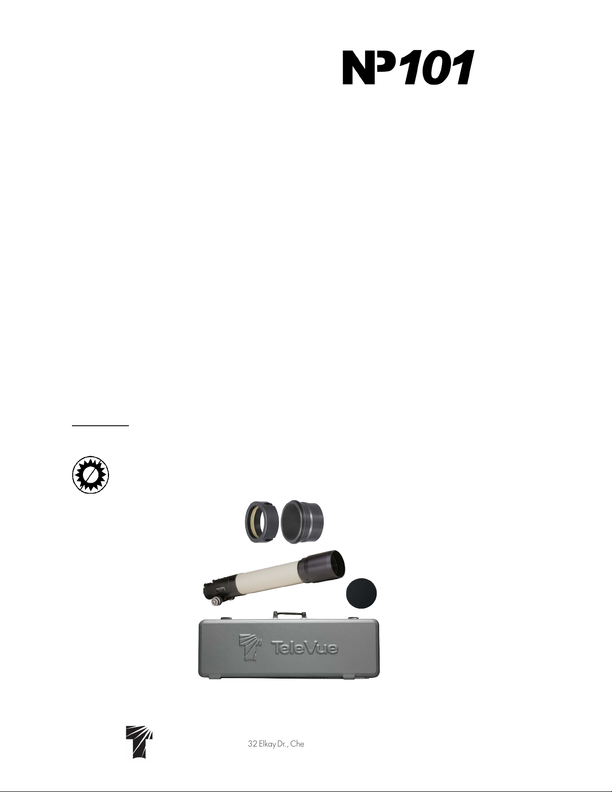
Lens Cap
Optical Tube Assembly
Case
2” Accessory Adapter (left)
Imaging System Adapter (right)
Standard Features - Optical tube assembly includes: captive sliding dew shield, 2.4” focuser with 10:1
Focusmate reduction, tilt adjustment end ring, screw-on metal lens cover, 2” Accessory Adapter, Imaging
System Adapter, custom hard-shell case, Allen Keys for end ring tilt adjustment.

2
Getting Acquainted with the Tele Vue-NP101is
1.1 Optical tube assembly
The optical tube consists of an air-spaced doublet in the front cell, which attaches to the tube via three
alignment screws. (Never touch the alignment screws in the front lens cell.) The rear doublet, making up
the rest of the 4-element objective, is larger in diameter than the older NP101 and provides additional
illumination at the edge of the field. This benefit is especially useful for large format CCD chips which
are extremely sensitive to light fall-off. The rear lens group is housed in the cell that threads between
the back of the tube and the focuser. Never stick any long objects into the focuser or you could hit the
rear-most lens surface.
1.2 Focuser
The 2.4” output side of the NP101is focuser is designed to pass all of the field rays exiting the rear
elements of the objective, as the forward end of the draw tube has a 3” internal diameter. A larger
focuser, therefore, lends no additional illumination benefit.
The telescope is shipped in its “visual” configuration. The 2” Accessory Adapter sits within the 2.4”
inside diameter of the drawtube. Thumb screws pass through both the drawtube and adapter to cinch
a brass clamp ring around 2” accessories. With three thumb screws there is enough holding power for
the heaviest of visual accessories!
The two tension screws on the top of the focuser body can be adjusted to add resistance when
using heavy equipment. These tension screws tighten against a brass clamp ring, which then cinches
down on the Teflon sleeve in which the draw tube slides. For photography it is not necessary to tighten
beyond the need to keep a camera station-
ary but we do recommend to tighten them
in unison to avoid any focus shift. Note that
even when sufficiently tight, the focuser knobs
can still drive the draw tube.
The end ring can be adjusted (and locked)
to compensate for any tilt effects seen in CCD
imaging. Lock screws in the end of the draw
tube tighten against either the taper of the
Imaging System Adapter or brass clamp ring
within the 2” Accessory Adapter.
Operation of the rack and pinion focuser
is via the 10:1 ratio Focusmate on the right
side or either of the 1:1 knobs. You might
consider the optional Focusmate Driver for
vibration-free focus control.
10:1 Knob
1:1 Knob
Lock Screws
(typical)
Jack Screws (typical)
Jam Screws
(typical)
1:1 Knob
Drawtube Tension
Screw (typical)
Focuser with 2” accessory adapter in place
2” Accessory
Adapter
3
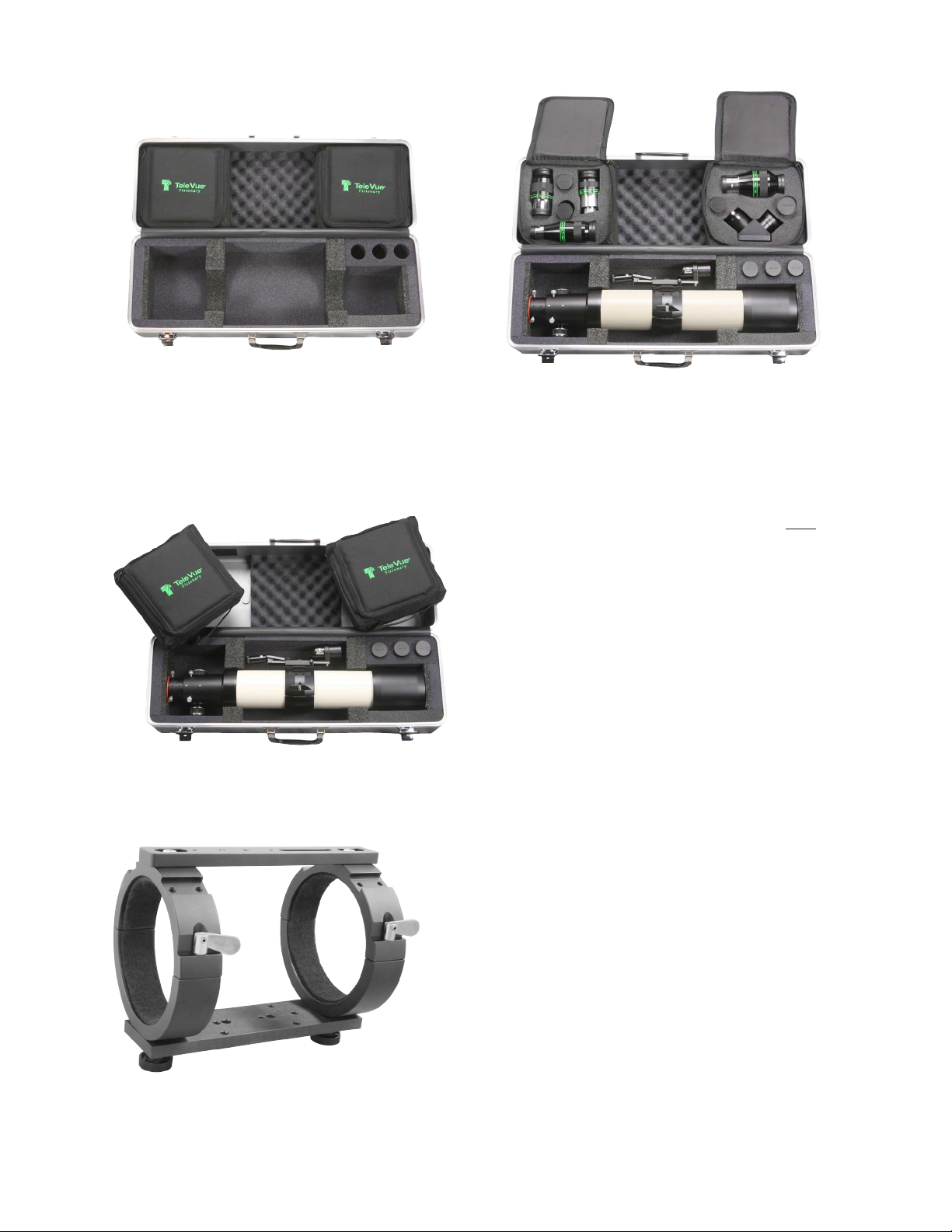
1.3 Case
When opening the case, we recommend always lifting the lid while holding the handle. The lid opens
a full 180° and holding the handle will give you a better grasp to insure that the lid doesn’t slip out of
your hand. The interior of the case was designed to store your scope with the optional Starbeam, and
Focusmate Motor Driver installed. To fit the Starbeam, you may have to reposition your ring mount so that
the Starbeam fits in the lid of the case between the accessory bags.
The two accessory bags within the case lid are removable. IMPORTANT: Whenever carrying
your telescope in the case, the accessory bags must be
in place as they act to hold the telescope down. Failure
to do so may result in the telescope rolling into the lid of
the case and damage to the telescope may occur. These
bags are held in place by Velcro and can be easily
lifted out. Each bag will hold a variety of accessories,
so remove the foam inserts as your needs require. The
right side bag is where you’ll find the Imaging System
Adapter. There is also a cutout for an optional Everbrite
diagonal with 2” to 1¼” adapter inserted. Remember
to zipper the bags closed before closing the case lid!
2.0 Mounting Options and Set Up
The telescope tube diameter is 4”. Tele Vue has two mount ring options available. The single ring (RS4-
8004) and the dual ring (MRS-4011). The single ring is fine for visual and photographic use. It contains two
machined grooves that accept the Starbeam (SRT-2010) unit
powerfinder, thePiggy-Cam (PGC-1001)piggy backcamera
adapter, and Sol Searcher. The RS4-8004 is recommended
for use with all Tele Vue Alt-Az mounts as it allows greater
balancing opportunities than the MRS-4011.
The dual ring MRS-4011 is best suited for critical photog-
raphy and CCD imaging. It also has grooves for mount
accessories. A central bar spans across the top of the two
rings and permits varying the spacings between the rings in
order to fit a variety of mount heads. The BPL-1098 adapter
plate, on the bottom of the rings, mounts directly to Tele Vue
Alt-Az mounts and is drilled to mate to a variety of mounts or
mounting adapterplates. Therings containa ¼”-20threaded
hole to allow for mounting to third party adapter plates.
MRS-4011 - Heavy duty tube ring set with
slotted spreader bar to adjust ring spacing
for a wide variety of equatorial mounts.
Optional Accessories Shown
Optional Accessories Shown

4
For Alt-Az mounting, Tele Vue recommends the Gibraltar-HD
or Gibraltar5-HD due to their sturdy legs. You will receive the
necessary attachment hardware and complete mount assembly
instructions with the mount. Tele Vue makes various adapter plates
for popular German equatorial mounts. Please consult your dealer.
The bottom of both mount ring systems have ¼-20 holes to
accept mounting studs or screws. The thread size in the accessory
groove is #10-32. Telescope balance in both systems is achieved
by unlocking the “bat handle” screws and sliding the tube fore or
aft. Once repositioned, retighten the bat handle screws.
3.0 Visual Observing Set Up
In order to use the scope visually, the 2.4” diameter of the draw-
tube needs to be reduced to 2”. This is achieved by installing the
included 2” Accessory Adapter. Note the three grooves with holes
machined 120° apart. The grooves will help index the holes in the adapter to the thumb screws in the
end ring. This will ease installation in the dark.
To install the 2” accessory adapter,
loosen the three end ring lock screws sufficiently
to remove any accessory that may be in place,
but do not retract them fully into the focuser body.
By allowing them to protrude into the body, they
act as locators. Insert the 2” Accessory Adapter
into the end of the focuser. If it does not go all the
way in, rotate the adapter. When the grooves in
the adapter align with the protruding screws, the
adapter will seat fully into the focuser. Tighten the
three screws a few turns so they enter the holes in
the adapter. The lock screws will now act against
the brass clamp ring in the 2” Accessory Adapter.
Slip a Tele Vue 2” Everbrite diagonal into
the focuser and tighten the lock screws. You will
now be able to reach focus with any Tele Vue
eyepiece.
IMPORTANT CAUTION: When replacing the orange plastic plug into the 2” Accessory Adapter, push
it in far enough to seat. Do not use the lock screws to clamp the plug in place as the clamp screws will
distort the brass clamp ring in the 2” accessory adapter.
3.1 Eyepieces
With its highly corrected wide, flat field and fast f/ratio, the NP101is puts eyepieces to the test. This
scope demonstrates the superiority of Tele Vue eyepiece performance and, with a range of 10x to 180x
(if the atmosphere allows) there is a magnification for all purposes. Atmosphere permitting, even higher
power can be achieved with Barlow and Powermates. See chart at the end of this manual or call Tele Vue
for recommendations. In general, we suggest choosing low and medium power eyepieces in ratios of
field stop diameters. For example, factors of 1.4 or 2.0. When choosing higher power eyepieces, use
ratios of magnification. (See eyepiece reference chart on last page of this manual.)
3.2 Finders
We particularly recommend using the Starbeam reflex sight (part# SRT-2010), which attaches to the Ring
Mount or Tube Rings. The case has a cutout for the Starbeam. The Quick Release Universal Finder Bracket
(QFM-1008) can hold a traditional 50mm finderscope and also attaches to the mount ring channels.
Lock Screws threaded
partially in to use as
guides for inserting
the 2” Accessory
Adapter.
RS4-8004 - Slotted for accessories, three
¼-20 tapped holes for attachment.

5
4.0 Photographic Set Up and the Tele Vue Imaging System
Tele Vue Imaging System Accessories provide solid threaded connections between components. To use
these accessories requires the insertion of the Imaging System Adapter (ISA) into the focuser. You will find
the ISA in the accessory compartment in the lid of the telescopes case. To install the ISA, first back off the
three Lock Screws far enough to pull the 2” Accessory Adapter out from the drawtube to reveal the 2.4”
diameter. Store the adapter in the accessory compartment in the case.
You will then need to back out the screws further so their ends are flush with the inside diameter of
the End Ring. Insert the ISA and tighten the three Lock Screws located equidistant around the end ring.
Visual Adapter removed and the three lock screws
are made flush with the end ring. Insert the Imaging
System Adapter and tighten the three lock screws.
Arrangement for imaging.
Imaging System
Accessory Adapter
Visual adapter removed.
2” Accessory Adapter removed
and lock screws backed out.
The Imaging System’s threaded accessories provide a variety of options for camera adaptation and
focal length variation. The goal of Tele Vue’s Imaging System is to let you pursue your astrophotographic
passion with ease, by providing accessories designed to work together. The following summary of parts
and pictorial diagrams will help you understand each part’s use and its sequence in the chain. Please
note that spacing requirements of any particular camera will need to be met by the appropriate Imaging
System spacer or combination of spacers.
6
LCL-1069 Large Field Corrector
• Optimizes edge of fi eld performance. Recommended for 35mm CCDs (43mm diagonal) and larger
plus cameras with pixel sizes < 6µm.
NPR-2073 – 0.8x Reducer for NP and NPis series telescopes
• Designed to enlarge the fi eld of all NP scopes for up to full-frame (43mm diagonal) imaging and is
a replacement for the previous NPR-1073 0.8x for up to APS size (27mm diagonal) formats
• Constructed to fi t both standard 2” focuser NP scopes (RAD-1074 required) and the threaded “NPis”
Accessories on the input end. Requires additional Imaging System rings to connect to imaging train.
STL-1071 – SBIG STL series camera adapter
• This adapter is sized to thread directly onto the STL series cameras and mates with I.S. Accessories.
TRG-1072 – Standard T-ring adapter
• This is the most restrictive of adapters in terms of vignetting as it has the smallest inside diameter.
Recommended for use with APS size or smaller formats.
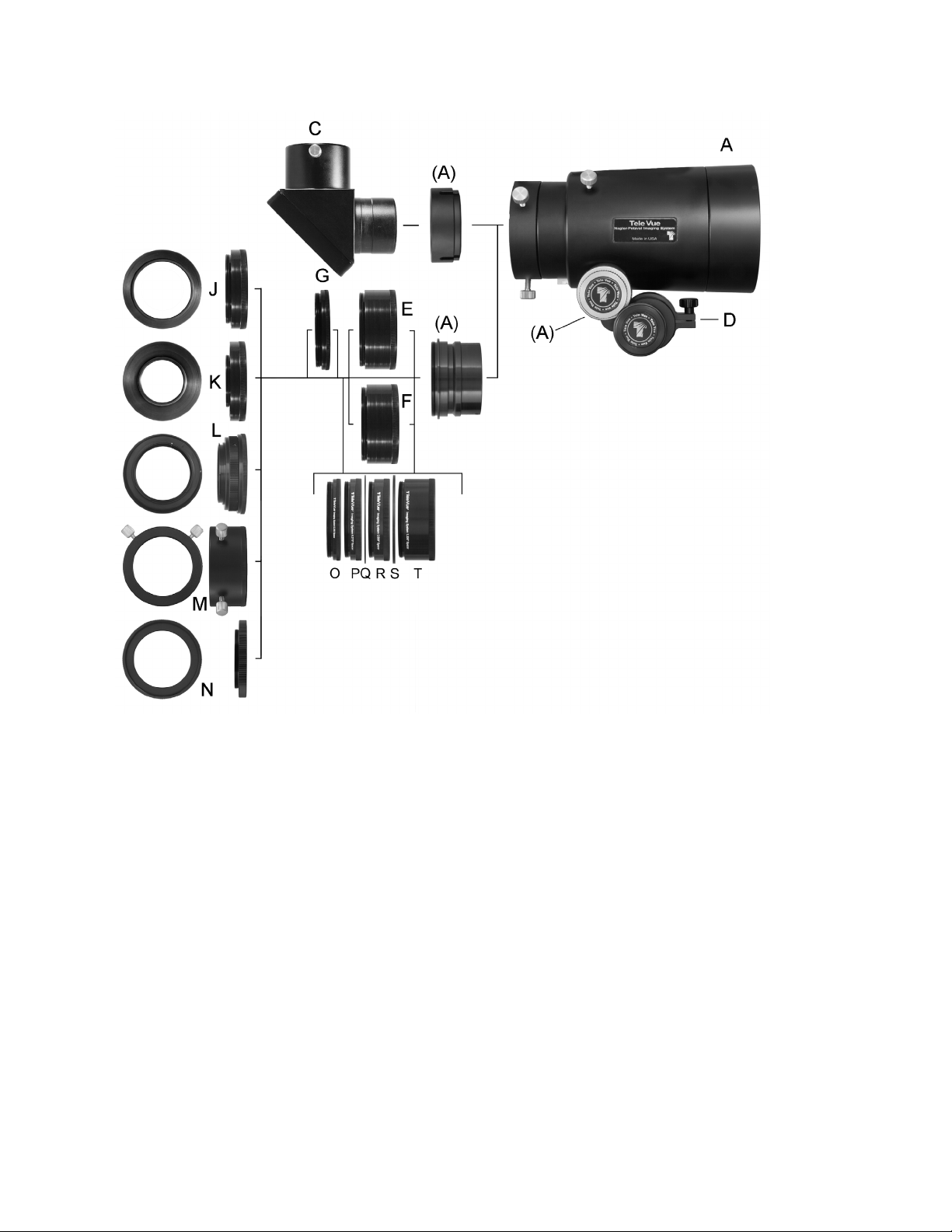
Focuser Features
A. Large Focuser for NP101is and NP127is
Standard features (A) include:
•Drawtube with 3” entrance aperture, 2.4” exit aperture
•End-ring with tilt capability
•3-Lock knobs to secure camera equipment or 2” adapter
•Body has brass clamp ring with 2 lock knobs
•10:1 Focusmate dual speed focuser
•Indexed 2” accessory adapter with brass clamp ring
•Imaging insert threaded for imaging system components.
Accessories (optional)
C. DDP-8004 2” Everbrite Star Diagonal w/2”-1¼” Adapter
D. FDF-2004 Focusmate Driver electronic vari-speed
motor control.
E. LCL-1069 Large Field Corrector for optimized edge
performance on NP101is and NP127is
F. NPR-2073 0.8X reducer
G.AFT-1105 48mm Filter adapter
J. STL-1071 SBIG STL series adapter
K. TRG-1072 Standard T-Ring adapter
L. CWT-2070 Canon / NWT-2073 Nikon Wide T adapter
M.A2A-1107 2” Accessory adapter
N. M54-1073 M54 Camera Adapter
O.TLA-0250 0.25” long threaded extension
P. TLB-0375 0.375” long threaded extension
Q.TLF-0040 0.040” spacer
R. TLC-0500 0.500” long threaded extension
S. TLG-0080 0.080” spacer
T. TLD-1000 1.000” long threaded extension

7
4.2 Prime Focus
Prime focus photography involves attaching a camera, without its lens, to the telescope. In this method the
telescope becomes the camera’s lens. In the case of the NP101is, it is a 540mm focal length, f/5.4 tele-
photo. It is the focal length of the telescope in combination with the diagonal dimension of the CCD chip
or film frame that will determine the amount of field your photograph will cover. The shorter the focal length
or larger the diagonal dimension, the greater the field that will be recorded.
The parts necessary for Prime Focus photography are: camera body, accessories (filter wheel /drawer,
off axis guider, etc.) appropriate Imaging System adapter, Large Field Corrector or 0.8x reducer with Ex-
tension Spacers to achieve proper back focus, drawtube Extension Spacers to limit drawtube extension to
approximately 0.75” (20mm), the Imaging System adapter, and telescope. See the following diagrams for
a visual explanation.
CWT-2070 – Canon / NWT-2073 – Nikon Wide T Adapter
• Mates Canon EOS or Nikon F-mount body with Imaging System Accessories.
• Eliminates the inner portion of Canon and Nikon T-rings to provide a larger diameter opening for
reduced vignetting.
A2A-1107 – 2” Accessory Adapter
• Use for cameras with 2” nosepiece or any other 2” accessory.
• Dual thumb-screws and clamp ring for positive locking.
M54-1073 M54 Camera Adapter
• Used for full-frame cameras with M54 x 0.75mm threads.
• Can also connect to filter wheels with M54 threads.
AFT-1105 –48mm Filter adapter
• Allows use of 48mm fi lters in the system.
• Best if used closest to the chip to minimize any vignetting
• Adds 0.25” of spacing.
TLA-0250 – 0.250” (6.4mm) Spacer
TLB-0375 – 0.375” (9.5mm) Spacer
TLC-0500 – 0.500” (12.7mm) Spacer
TLD-1000 – 1.000” (25.4mm) Spacer
TLF-0040 – 0.040” (1mm) Spacer
TLG-0080 – 0.080” (2mm) Spacer
TLS-2245 – Set of all six spacer rings.
• Threaded coupling provides the necessary distance for proper spacing of fi eld lenses to CCD chip.
Required spacers will vary depending on camera specifications. 0.040” and 0.080” rings fit between
the threaded spacers.
• Black anodized aluminum with anti-refl ection threads for maximum contrast.
4.1 Adjustable Position End Ring
The tilt of the End Ring is pre-set to ensure the end surface is parallel with the focal plane. If you see tilt
errors in your images, the optical axis can be changed to compensate.
To determine which way to tilt the End Ring, it is necessary to focus on the part of the image that
comes to focus first when racking out the focuser from its “in” position. That will permit adjusting, or
“jacking,” the End Ring “out” to match that focus point in other parts of the field
You will need to remove your camera equipment, including the Imaging System Adapter to adjust the
tilt of the End Ring. Slightly loosen the three Jamb Screws located on the face of the End Ring with the ap-
propriate Allen key. Then, “jack” the End Ring to the desired position using the appropriate Allen key Jack
Screws. Note: when adjusting the jack screws, make very slight turns as a ¼ turn equals a longitudinal
movement of 198 microns at the screw. Tighten the Jamb Screws against the End Ring and reinstall your
camera. Some trial and error imaging will be necessary, so it is best to carry out any adjustment during
an imaging session.

8
2. One Shot Color or DSLR Camera with 0.8X Reducer (NPR-2073)
3. Full-Frame Camera with Large Field Corrector (LCL-1069)
1. Prime Focus
Imaging
Insert
Shoulder
Drawtube
extended
¾” (20mm)
Spacers to minimize
drawtube extension
Imaging System
to Camera
Adapter
Camera
Sensor
Image
Plane Total distance from Imaging Insert
shoulder to camera sensor
Note: while not critical, try to use spacers to achieve about ¾” (20mm) drawtube
extension. “Spacers” path length can be replaced with filter wheels, off axis guider, etc.
Imaging
Insert
Imaging
Insert
Drawtube extended
¾” (20mm)
Drawtube extended
¾” (20mm)
Spacers to minimize
drawtube extension
Spacers to minimize
drawtube extension
Imaging System
to Camera
Adapter
Imaging System
to Camera
Adapter
Camera
Sensor
Image
Plane
Camera
Sensor
Image
Plane
The total path length of the imaging train between the
camera and shoulder of the NPR-2073 is:
68mm – “chip to faceplate distance”
Within this path length you can put your filter wheel, off
axis guider, spacers, and Imaging System camera adapter.
See NPR-2073 information in the Prime Focus section of the
manual for details.
The total path length of the imaging train between the camera
and shoulder of the LCL-1069 is:
Within this path length you can put your filter wheel, off axis
guider, spacers, and Imaging System adapter. See LCL-1069
information in the Prime Focus section of the manual for details.
NPR-2073
Shoulder
LCL-1069
Shoulder
Camera Setup Examples
In the examples here, spacers shown are for illustrative purposes: your spacing will be unique. For instances where
accessory lenses are not used, spacers will only determine focus position and therefore are not critical.
For full-frame cameras: 2.75” (69.85mm) – “chip to faceplate distance”

9
Large Field Corrector Usage. To obtain the best edge sharpness with 35mm or larger formats or in all
sensor formats when the sensor pixels are < 6 µm, you must use the Large Field Corrector (LCL-1069). For
optimum performance, the distance from the base of the male thread on the camera-facing side of the LCL-
1069 to the camera sensor must be 2.75”. In order to determine how much Back Focal Length (BFL) you
need to maintain between the camera face and LCL-1069, you need to know the distance from the chip
to the faceplate of the camera. This should be specified in the camera’s documentation; call your camera’s
manufacturer if it is not. Simply subtract “chip to faceplate” distance from 2.75” to get the spacing required
from the Large Field Corrector to your camera faceplate, for up to 35mm formats. If accessories such as
filters wheels or off axis guiders are used, their path length must also be deducted from the 2.75” figure.
For larger formats, such as 53mm diagonal sensor, use 2.67” instead of 2.75”.
Since there are tolerances in all manufactured parts, it may be necessary to vary the spacing slightly
from the nominally calculated value. Should your star images in the four corners look equally slightly elon-
gated, try using the next smallest increment of threaded spacer with either the 0.040” (TLF-0040), 0.080”
(TLG-0080), or both in between the threaded spacers to fine tune the image.
4.2a) 0.8x Reducer (NPR-2073) Usage. To gain more field with chips up to full-frame, use the 0.8x Reducer
(NPR-2073). For One Shot Color and DSLR cameras, use a Back Focal Length (BFL) of 68mm. In the case
of imaging in full-frame monochrome with LRGB or HST palette filters, a BFL of 50mm should be used (this
includes the +1mm shift required for a single 3mm filter). If your imaging stack exceeds 50mm due to ac-
cessories, then use the 68mm distance. Just subtract from either of these distances the “chip to faceplate”
distance to get the spacing required from NPR-2073 to your camera faceplate. If accessories such as filters
wheels or off axis guiders are used, their path length must also be deducted from the 68mm figure. For all
setups, use Extension Spacers to minimize draw tube out-travel to no more than ¾“ (20mm). See NPR-2073
instruction sheet for details.
4.2b) Special Note for ZWO Usage. ZWO instructions are standardized on producing an imaging stack
with 55mm Back Focal Length using their various cameras, filter wheels, Off Axis Guiders, and adapter
rings. In order to properly back space the sensor behind our optical accessories, simply subtract 55mm
from our recommended spacing distance and add back 1mm for every 3mm of filter thickness. Using our
2.75” (69.85mm) spacing example for the Large Field Corrector with a 3mm filter, the math is as follows:
69.85mm – 55mm + 1mm = 15.85mm of additional spacing is required. Our TRG-1072 (M42x0.75mm)
or M54-1073 (M54x0.75mm) adapters (6.6mm of path) will connect to the telescope end of the ZWO
55mm stack (in some cases use ZWO’s M48-M42 zero path length converter). Next, simply thread on our
TLB-0375 (9.5mm of path) to achieve the required path length.
Likewise, employing ZWO’s 55mm stack with the 0.8x Reducer (NPR-2073), requires use of the
68mm back focus option in all cases as the 50mm option is not possible. This spacing with a 3mm thick
filter requires: 68mm – 55mm + 1mm = 14mm more spacing. Pairing our TRG-1072 or M54-1073
(6.6mm of path) adapters with the TLA-0250 (6.4mm of path) and TLF-0400 (1mm of path) exactly makes
up that 14mm requirement.
4.2c) To gain more magnification, the 2x (PMT-2200) and 4x (PMT-4201) Powermates are recommended
for best performance. Start by inserting the 2” Accessory Adapter into the end of the focuser. (Since in-
creasing the magnification will reduce the field, the large opening provided by the Imaging System Adapter
is of no benefit.) The arrangement of parts necessary is: camera with a T-ring attached, Powermate with
corresponding T-ring adapter (PTR-2200 or PTR-4201) attached, 3.5” Extension Tube (X3C-0009), to
make up focus travel, and telescope.
If you prefer to use the threaded I.S. adapters, you would need three 1” spacers (3x TLD-1000) plus
the 2” Accessory Adapter (A2A-1107). Start by inserting the ISA into the end of the focuser. The arrange-
ment of parts necessary is: camera with a T-ring attached, Powermate with corresponding T-ring adapter
(PTR-2200 or PTR-4201) attached, 2” Accessory Adapter (A2A-1107) and three 1” spacers (3x TLD-1000)
to make up focus travel, and telescope.
There are certainly a variety of ways of setting up the Tele Vue-NP101is for photography!

10
5.0 ADDITIONAL ACCESSORIES
5.1) The Focusmate Driver for the NP101is (FDF-2004) electronically
drives the fine focus knob of the 10:1 Focusmate in steps of approximately
0.0005” per button click. With the button depressed, the motor drives
the Focusmate continuously without vibration transferred to the system.
Motor speed is variable. The motor has a standard phone jack that will
accept a cord of any length.
For remote focusing options, we suggest contacting Starlight Instru-
ments or Optec for their offerings. While there may be other options
available we cannot guarantee a direct fit to our pinion assembly.
5.2) The
NP101is
package (TVP-4058) is designed for visual use of this
scope. It includes the 4” clamshell-style Ring Mount with ¼”-20 mounting
threaded holes to attach to a heavy-duty tripod or telescope mount, 2”
90° Everbrite Diagonal (99% reflection across visual spectrum) with 2” to
1¼” adapter, and 18.2mm DeLite eyepiece, with 20-mm eye-relief, that
yields a 2° true field of view at 30x in this scope.
6.0 Caring for your NP101is
The Tele Vue-NP101is requires no special care. Treat it as you would any fine camera lens. Use the lens
cap when the telescope is being stored or not in use. The captive dew shield provides protection from glare,
helps protect the lens from dust or spray blown in by the wind and minimizes dew formation on the lens.
If dew forms on the lens during cold weather, it is best to use a hair dryer (on the lowest setting) to
gently warm it away. A few specks of dust will have no effect on image quality and may be gently blown
off with a squeeze bulb. Do not use compressed air cans to blow dust off optical surfaces.
To prevent dew formation when bringing the scope in from the cold, we advise to close the cold
scope in its case before bringing it into the warm indoors. Do not open the case until the scope has come
up to room temperature.
Fingerprints or oils should be cleaned off the lens surface. Though the anti-reflection coatings are
durable, they can be scratched. The simplest cleaning method is to moisten a very soft, lint-free tissue,
cloth, “Q-Tip” or surgical cotton with a lens or glass cleaner and working in a circular motion, gently whisk
away the stain. Do not apply any solutions directly to the glass surfaces. After every cleaning stroke, use
a fresh applicator. The fewer strokes the better! Any residual “film” will not affect visual performance.
Collimation of your Tele Vue-NP101is has been locked at the factory. With reasonable care it will
remain aligned. However, rough handling or improper packaging for shipment can cause misalignment.
WARNING: The button head screws in the front lens cell are filled with epoxy. Loosening these screws
will cause misalignment. If necessary, contact Tele Vue for re-collimation.
Your star diagonal employs a first-surface mirror. Like all first-surface mirrors, it should be cleaned only
when absolutely necessary. First blow loose dust away with a squeeze bulb. CAUTION: Do not clean
the mirror with water or water based cleaners such as Windex or any other commercial lens cleaners;
this is not a lens. All contain too much water and will leave stains. Moisten a “Q-Tip” with pure acetone,
methanol or Isopropyl alcohol, reagent grade. Clean gently using only the weight of the cotton swab.
Use light pressure and never rub. Slight residual stains or dust have no visible effects in observing.
The tube is powder-coated for durability and can be waxed with any nonabrasive car wax. Black
anodized surfaces can be cleaned with Windex. If you have any questions about the care, operation or
performance of your Tele Vue-NP101is, please call us at (845) 469-4551 from 9:30 am to 5:00 pm EST.
TVP-4058 Package

11
7.0 Warranty
Tele Vue telescopes are warranted to be free of manufacturing or workmanship defects for 5 (five) years
from the date of purchase, to the original owner. Please return the warranty card as validation of your
ownership and for easy identification. If your Tele Vue telescope requires warranty service, please call
Tele Vue to discuss the problem, upon which you will receive a return authorization. NO RETURNS ARE
ACCEPTED WITHOUT PRIOR AUTHORIZATION. A copy of your sales receipt maybe requested if you
have not submitted your warranty registration material.
The warranty does NOT include: collimation, defects caused by mishandling, defects of subjective
nature, or coverage for any telescope purchased through an unauthorized Tele Vue dealer. However, for
claims of telescopes arriving out of collimation you must contact Tele Vue Optics within 30 days from date
of delivery, verifiable by sales receipt.
Warranty work will be performed at Tele Vue’s discretion and may only be performed by Tele Vue
Optics or Tele Vue authorized agent. The telescope must be shipped in its case with proper inner and outer
packaging. Shipping and insurance charges are the purchaser’s responsibility.
8.0 Specifications
Type 4-element, flat field, APO refractor, Fully Multi-Coated
Clear Aperture 4 inches (101.6mm)
Aperture Gain 211, compared to a 7mm exit pupil
Focal Length 540mm
Focal Ratio f/5.4
Resolution (visual) 1.1 arc-sec. (Dawes Limit for a 4 inch aperture)
Resolution 267 line pairs per mm
(photographic)
Magnification 10x to 270x using Tele Vue eyepieces
Field, Visual 4.9oat 10x
Focuser 2.4-inch, rack and pinion type
Diagonal Accepts optional 2-inch 99% reflective dielectric coating, with 1¼” adapter
Finder Optional Starbeam or 55mm Plössl for 10x, 4.9ofield
Mounting Optional adjustable ring mount or tube rings with ¼-20 tapped holes for
standard photographic tripods or optional Tele Vue and Vixen mounts
Weight 10.6 lbs. (tube assembly) 19 lbs. in case, 28 lbs. shipping
Length 26-inches (O.T.A. only)
Accessories included as standard: custom fitted case, screw-on lens cover, sliding dew (glare) shield,
2” Accessory Adapter, Imaging Systems Adapter
Tube Powder-coated aluminum
Specifications subject to change without notice.

Tele Vue recommends choosing low and medium power eyepieces in ratios of field stop diameters. For
example, factors of 1.4 or 2.0. When choosing higher power eyepieces, use ratios of magnification.
NOTE: True Field in degrees = (Field Stop dia./Telescope Focal Length) X 57.3°
*Indicates additional Dioptrx Adapter required
†55mm Plössl requires 2” Eyepiece Barrel Extender (product code EBX-2120) or pull out from diagonal to reach focus. The large exit pupil will dim the image
compared to other offerings with 2” barrels.
Tele Vue-NP101/NP101is
Focal
Length
(mm)
Type Product Code Apparent
Field (deg)
Field Stop Dia.
(mm)
Eye Relief
(mm)
Weight
(lb.) Mag.
True
Field
(deg)
Exit
Pupil
(mm)
# of
Elem.
Dioptrx
Ready
2" Eyepieces for Wide True Fields
55 Plössl EPL-55.0† 50 46.0 38 1.1 9.8 4.88 10.3 4 Y
41 Panoptic EPO-41.0 68 46.0 27 2.1 13.2 4.88 7.7 6 Y
31 Nagler 5 EN5-31.0 82 42.0 19 2.2 17.4 4.46 5.8 6 Y
35 Panoptic EPO-35.0 68 38.7 24 1.6 15.4 4.11 6.5 6 Y
21 Ethos ETH-21.0 100 36.2 15 2.3 25.7 3.84 3.9 - Y
22 Nagler 4 EN4-22.0 82 31.1 19 1.5 24.5 3.30 4.1 7 Y
27 Panoptic EPO-27.0 68 30.5 19 1.0 20.0 3.24 5.1 6 Y
17 Ethos ETH-17.0 100 29.6 15 1.6 31.8 3.14 3.2 - Y
1¼" Eyepieces for Wide True Fields
40 Plössl EPL-40.0 43 27.0 28 0.4 13.5 2.87 7.5 4 Y
32 Plössl EPL-32.0 50 27.0 22 0.4 16.9 2.87 6.0 4 Y
24 Panoptic EPO-24.0 68 27.0 15 0.5 22.5 2.87 4.5 6 Y*
13 Ethos ETH-13.0 100 22.3 15 1.3 41.5 2.37 2.4 - Y
16 Nagler 5 EN5-16.0 82 22.1 10 0.4 33.8 2.35 3.0 6 N
19 Panoptic EPO-19.0 68 21.3 13 0.4 28.4 2.26 3.6 6 Y*
25 Plössl EAP-25.0 50 21.2 17 0.3 21.6 2.25 4.7 4 N
17.3 Delos EDL-17.3 72 21.2 20 0.9 31.2 2.25 3.2 - Y
18.2 DeLite EDE-18.2 62 19.1 20 0.5 29.7 2.03 3.4 - Y
10 Ethos ETH-10.0 100 17.7 15 1.1 54.0 1.88 1.9 - Y
13 Nagler 6 EN6-13.0 82 17.6 12 0.4 41.5 1.87 2.4 7 Y*
14 Delos EDL-14.0 72 17.3 20 0.9 38.6 1.84 2.6 - Y
20 Plössl EAP-20.0 50 17.1 14 0.2 27.0 1.81 3.7 4 N
11 Apollo (disc) EAL-11.0 85 16.2 18 1.4 49.1 1.72 2.1 - Y
15 DeLite EDE-15.0 62 16.0 20 0.5 36.0 1.70 2.8 - Y
1¼" Eyepieces for Medium Powers
12 Delos EDL-12.0 72 15.0 20 0.9 45.0 1.59 2.2 - Y
13 DeLite EDE-13.0 62 13.8 20 0.5 41.5 1.46 2.4 - Y
10 Delos EDL-10.0 72 12.7 20 0.9 54.0 1.35 1.9 - Y
15 Plössl EAP-15.0 50 12.6 10 0.2 36.0 1.34 2.8 4 N
9 Nagler 6 EN6-09.0 82 12.4 12 0.4 60.0 1.32 1.7 7 Y*
11 DeLite EDE-11.0 62 11.7 20 0.4 49.1 1.24 2.1 - Y
9 DeLite EDE-09.0 62 9.6 20 0.5 60.0 1.02 1.7 - Y
11 Plössl EAP-11.0 50 9.1 8 0.1 49.1 0.97 2.1 4 N
1¼" Eyepieces for Higher Powers
8 Ethos ETH-08.0 100 13.9 15 1.0 67.5 1.47 1.5 - Y
6 Ethos ETH-06.0 100 10.4 15 1.0 90.0 1.10 1.1 - Y
8 Delos EDL-08.0 72 9.9 20 1.0 67.5 1.05 1.5 - Y
7 Nagler 6 EN6-07.0 82 9.7 12 0.5 77.1 1.03 1.3 7 Y*
4.7 Ethos SX ETH-04.7 110 8.9 15 1.3 114.9 0.95 0.9 - Y
6 Delos EDL-06.0 72 7.6 20 1.0 90.0 0.81 1.1 - Y
7 DeLite EDE-07.0 62 7.5 20 0.5 77.1 0.80 1.3 - Y
3.7 Ethos SX ETH-03.7 110 7.0 15 1.1 145.9 0.75 0.7 - Y
5 Nagler 6 EN6-05.0 82 7.0 12 0.5 108.0 0.74 0.9 7 Y*
8 Plössl EAP-08.0 50 6.5 6 0.1 67.5 0.69 1.5 4 N
4.5 Delos EDL-04.5 72 5.6 20 1.1 120.0 0.59 0.8 - Y
5 DeLite EDE-05.0 62 5.3 20 0.5 108.0 0.56 0.9 - Y
3.5 Nagler 6 EN6-03.5 82 4.8 12 0.5 154.3 0.51 0.7 7 Y*
3.5 Delos EDL-03.5 72 4.4 20 1.1 154.3 0.47 0.7 - Y
4 DeLite EDE-04.0 62 4.3 20 0.5 135.0 0.46 0.7 - Y
3 DeLite EDE-03.0 62 3.2 20 0.5 180.0 0.34 0.6 - Y
1¼" Zoom Eyepieces for Medium and Higher Powers
6-3 Nagler Zoom ENZ-0306 50 5.1-2.6 10 0.3 90.0-
180.0
0.54-
0.28
1.1-
0.6 5 N
Other manuals for NP101is
1
Table of contents
Other TeleVue Telescope manuals

TeleVue
TeleVue NP127is User manual

TeleVue
TeleVue 76 User manual

TeleVue
TeleVue Tele Vue-NP127fli User manual

TeleVue
TeleVue NP101is User manual

TeleVue
TeleVue Starbeam SFT-2003 User manual

TeleVue
TeleVue NP127is User manual

TeleVue
TeleVue 102 User manual

TeleVue
TeleVue 60 User manual

TeleVue
TeleVue NP127is User manual

TeleVue
TeleVue 85 User manual
Popular Telescope manuals by other brands

Meade
Meade 114 EQ-ASB instruction manual

ORION TELESCOPES & BINOCULARS
ORION TELESCOPES & BINOCULARS SpaceProbe 3 instruction manual

Orion
Orion StarBlast 62CTR instruction manual

Carson
Carson Skyseeker JC-1000 instruction manual

Bresser
Bresser National Geographic 20-60x60 operating instructions

Meade
Meade ETX-90PE instruction manual


