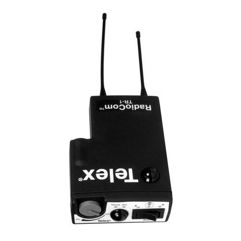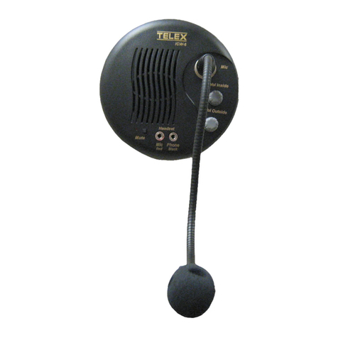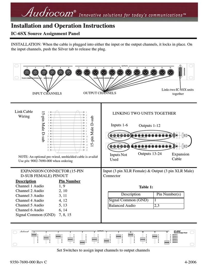
GENERAL INFORMATION
GENERAL DESCRIPTION
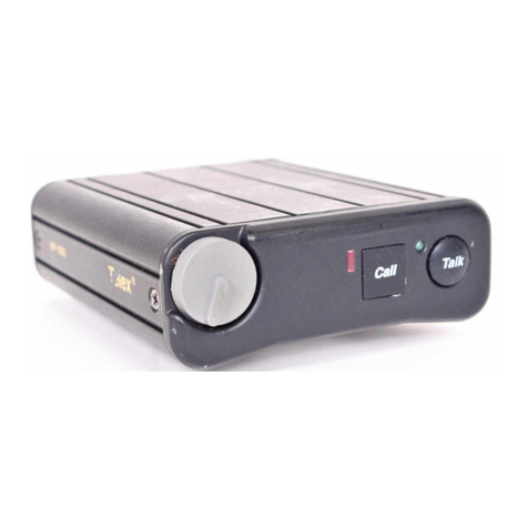
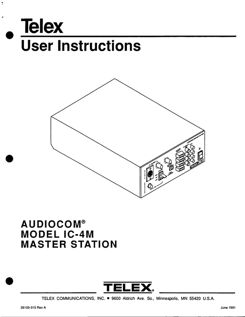
The Telex Audiocom'" Model IC-4M is afour-
channel master intercom station designed for
balanced-line operation. Itfeatures light
signaling, stage announce (public address)
output, auxiliary program input, and IFB
operation. It is also compatiblewith the Telex
Model IC-4SX System Expander.
The IC-4M is equipped with an internalpower
supply capable of poweringupto 150remote
stations. It is rack-mountable insingle or dual
configurations.
OPERATING FEATURES
FRONT PANEL
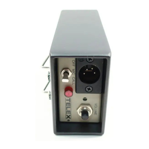
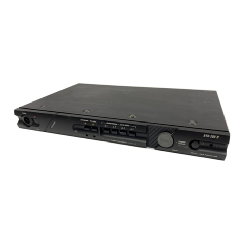
The front panel has a 4-pin XLR connector for a
dynamic-microphone headset.A 3-pin connector
is also providedfor acondenser-type gooseneck
microphonewhich can be used with an external
speaker connected at the rear panel. Separate
volume controls are provided for headset and
speaker.A three-position rocker switch is used
for microphoneon/off switching and for call light
signaling. A momentary-type stage announce
volume control adjusts the auxiliary input level.A
3-pin XLR receptacle connector provides a
balanced, transformer-coupled stage announce
output. A 9-pin D-type connector provides
system buss connection for an IC-4SX System
Expander.
The IC-4M has an integral power cord for ac
operation, and the main power fuse is accessible
on the rear panel.
SPECIFICATIONS
Interface Requirements:
-
Dynamic Headset: 50-600 ohm microphone;
150-600ohm headphones
-
Condenser Microphone: 6.8K ohm, -55 dB
sensitivity (typical)
-Speaker: &ohm, 5W
-Auxiliary Program Source: 100mV-10 Vrms
-
Channel Level: 1Vrms (0 dB) nominal
-
Impedance: Supplies 300 ohms termination to
channel
Power Supply:
-
Output Voltage: 25V regulated
-Output Current: 500 mA maximum continuous
per channel; 2 amp maximum continuoustotal
push-button switch allows the station operator to
page or make public address announcements
Power Requirements:
120V, 50-60 Hz, 90W
maximum (may be modifiedfor 220V or 240V
through an exernal PA system. operation)
Channel select on/off push-button switches,
momentary-type push-button IFBswitches, and
call indicator lights are provided for each
channel. The channel-select switches indicate
the "on" state by displaying acolor bar. A rocker-
type power off/on switch is provided along with
an LEDto indicate "power on".
REAR PANEL
HeadphoneAmplifier:
-
MaximumOutput: 12V p-p into 150ohms (120
mW);21V p-p into 600 ohms (90 mW)
-Frequency Response (Channel to Phones):200
Hz-7 kHz
-
Voltage Gain (Channelto Phones): Adjustable
from 0-26 dB
-
Sidetone: Adjustable from 25 dB nullto full-on
Speaker Amplifier:
-
Maximum Output: 3W into 8ohms at 1%THD
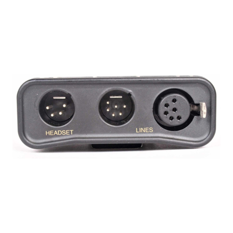
A 1M-inch (6.35 mm) phone receptacle
-
Voltage Gain (Channelto Speaker): Adjustable
connector accepts an external speaker (8ohms
minimum).A 3-pin XLR connector and a from 0-34 dB
receptacleconnector for each intercom channel
permit loop-through connection of intercom
channels.
A 3-pin XLR receptacle connector accepts either
balanced or unbalanced, line-level auxiliary
program input. A rotary switch assignsthe
auxiliary program to one or all intercom channels
and also has an "off" position.An auxiliary
Auxiliary Amplifier:
-
Input Impedance: 50K ohms balanced; 25K
ohms unbalanced
-
Frequency Response (Auxiliaryto Channel):
150HZ-10kHz
-Voltage Gain (Auxiliaryto Channel):
Adjustable from 0-30 dB (measured before
onset of AGC limiting)
-
Common Mode Rejection: 40 dB
