SECTION
2:
INSTALLATION
2.1
ELECTRICAL INSTALLATION/
GROUNDING
All
console, rack and wall mounted user station
chassis shouldbe connected to earthground or power
line safety ground, but the TW Intercom System
circuit ground should not be directly connected to
"earth" or "chassis" ground. Each user station is
bypassed to its own chassis via a 0.1 microfarad
capacitor to prevent interferencefrom radio stations.
The power supply has a bleeder resistor from circuit
ground to chassis ground (22 kilohms) to prevent
a
buildup of voltage across the system capacitance. If
the system has no RTS power supply, install a bleeder
resistor at a central point in the system.
There aretwo advantagesto not "earth"groundingthe
circuitground:
1) The system continues to operate during an
accidental grounding since this can be tolerated by
the systemuntilit can be cleared.
2) Earth currents from other equipment are
prevented from introducing noise into the
TW
Intercom System.
Portable user stations should not arbitrarily be
taped or fastened to metal structures. Grounding
the case of the user station to an arbitrary
structure may introduce large noise voltages due
to local ground currents or the due to the
completion of a "ground loop antenna". Always
clear
all
earth grounds from the RTS
TW
Intercom System circuit ground. The only ground
should be through the 22 kilohm resistor in the
power supply.
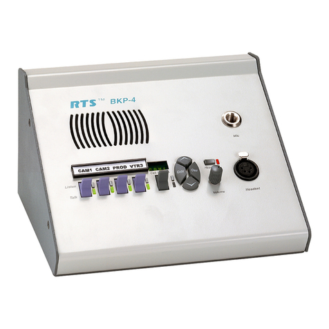
TheBP320 receives electricalpower from either:
1)
A
system power supply
(26
to 32volts
DC
on line
connector pins 2
(t)
and
1
(corn) (2 channel
operation) or
2) A local power supply option (12 to 18volts
DC).
A user station requires 18 to 33 volts to be
a
10,000 ohm bridging impedance across the
powering line, but the station
can
otherwise
operate (as in the local power option) from 12to
33 volts. Model BP320 current requirements
range from 20 to 50
mA;
BP320-L, from 30 to 60
mA.
Since, in
(I),
above, the power and
communicationssignals shareconductors, it may
be necessary to overcome power losses by
increasingconductor size over long runs (over 1/2
mile (804.67 m).
Typical
operating distance for
one BP320 station is
1
mile (1.609
km)
using a
normal #22 AWG conductor size; for a BP320-L,
3/4 mile (1.207
km).
23
ELECTRICALINSTALLATION/SIGNALS
The required number of conductors to interconnect
user stations is-asfollows: (For standard, unbalanced
TW user stations)
Number of Channels Number of Conductors
Use shielded cable to interconnect user stations in
areas of possible electricalinterference,(areas suchas
those near: digital equipment, high current primary
power conductors ("mains"), transformers,
transmitters and lampdimmers).
Most two channel applications may use either
standard microphone cable (for convenience) or two-
twisted-pair cable (considerably less expensive than
microphone cable). Standard wire size for the
TW
Intercom System is #22 gauge wire for
interconnection. For permanent installations it is
recommended that each channel should have
individuallyshieldedtwisted pair of at least #22 gauge
wire, such as Belden #8723 for 2 channels. For 3
channel installations using XLR type connectors, a
cable of
3
individually shielded wires such as Belden
#8733 may be used (using the 3 drain wires as circuit
ground. For 3 channel installations using terminals
blocks or tag strips, a cableof 3 twisted shielded pairs
such Belden #8777 maybe used (using the 3 drain
wires and one each of the three pair as circuit
ground). This
will
reduce interference and help
maintain a low crosstalk figure between channel.
Connect the shield to system common
but do not tie
the shield to chassis, earth or connector shell
ground.
Page 2-1


