Telex VEGA C-5110B User manual

Models C-5110B, C-5111, and C-5112
Ten-Line/Four-Frequency
Radio Control Consoles
Instruction Manual
098-0345A
C-5110B C-5111
C-5112

1
Contents
Introduction .........................................................2
Operation and Controls...............................................3
Installation ..........................................................6
Disassembly, Setup, and Adjustment ....................................7
Upper PC Board Programming and Adjustment ..........................9
Main (Lower) PC Board Programming and Adjustments ...................9
Optional Handset Adjustments .......................................10
Duplex Operation .................................................10
Timer Adjustments ................................................10
Notch Tuning and NotchOutphase Control .............................11
Auxiliary Audio Input and PTT ......................................11
Footswitch PTT ...................................................11
Tone-Burst Frequency Programming ..................................11
Paired F1-F2 and F3-F4 Operational Mode .............................11
Defeat F2, F3, and/or F4 ............................................11
Special Uses for F2, F3, F4 ..........................................11
Headphones ......................................................11
External Speakers .................................................11
Battery Backup or DC Supply Operation ...............................11
Special Transmit Audio Levels .......................................12
Switch PC Board Programming ........................................12
TX ALL Defeat ...................................................12
Line 1 to 10 Defeat ................................................12
Unselected Line 1 to 10 Defeat .......................................12
Theory of Operation, Control Panel ....................................12
TX ALL.........................................................12
Group Select .....................................................13
Individual PTT Switch PCB .........................................13
Individual Line Volume Controls .....................................13
Timed Mute......................................................13
Unselected Line Receive Circuits .....................................13
Debouncer Ics U8, U11, U13, U19 ....................................14
Line Drive and LineRecieverAudio Circuits (Upper-Main PCB Assembly) ...14
Main PCB Assembly .................................................15
Main PCB Receive Circuits............................................16
Main PCB Transmit Circuits..........................................17
Alert-Tone Generator ................................................17
Technical Assistance .................................................17
Warranty (Limited) ..................................................17
Claims .............................................................17
Specifications .......................................................18
C-5110B Parts List...................................................19
C-5112 Parts List ....................................................34

Introduction
The Models C-5110B, C-5111, and C-5112
10-line, four-frequency, tone-remote control
consoles provide reliable remote control of the
various functions of two-way radio base
stations located at up to 10 different sites. One
or any combination of the ten remote base
stations can be selected. The dispatcher can
monitor, through a second speaker, any
combination of lines not already selected for
transmit/receive control, and can transmit on
any of those lines with instant-PTT switches.
Individual volume controls are provided for
each “unselected receive” line. A timed mute
switch silences “unselected receive” lines.
The console is normally used in conjunction
with up to 10 functionally matching Vega 223C
Series (or equivalent) tone-remote panels
located at the base stations. The console is
compatible with General Electric, Motorola,
and other tone-remote control systems
employing the industry-standard sequential
tone-control format.
The console is connected to the mating panels
by means of voice-grade or better leased or
private lines (including microwave circuits).
Metallic or DC continuity is not required.
Note: Although the C-5112 Console has been
discontinued along with the accessories, this
manual still applies to the existing C-5112
consoles.
The C-5110B, C-5111, or C-5112 console
includes two speakers, and, when equipped
with an optional desk microphone, gooseneck
microphone, handset, or headset, is ready to
operate in the simplex two-wire mode.
Push-to-talk, CTCSS disable (monitor), three
2175-Hz notch filters, F1/F2/F3/F4 frequency
select, ten-line transmit/receive select, ten
unselected (receive-only, when not selected for
transmit/receive) line select, receive all,
transmit all (simulcast), and ten
line-activity-monitor functions are installed
and operational.
Plug jumpers are provided for simplex
two-wire operation and for simplex or duplex
four-wire operation. Additionally, jumpers are
provided for proper line termination impedance
on all lines with either single or multiple
consoles per line. Jumpers have also been
provided to disable operation of any of the
line-selection controls.
Accessories available for the C-5110B, C-5111,
and C-5112 consoles on special order and at extra
cost include:
•DTMF-12 12-button DTMF-pad encoder
•FS-1 footswitch
•HA-1 handset and cradle (no hookswitch)
•HA-2 handset and cradle (with hookswitch)
•HE-2 headset with PTT switch and adapter
•MD-MS desk microphone (Merry, modern
style; available March 1993)
•MD-S desk microphone (Shure 450)
•MG2-A gooseneck mic
•XM-1 cross-mute PCB.
Accessories available strictly for the C-5110B
and C-5111 consoles include:
•CV-1B clock/audio-level display
•CV-1BR rack-mount panel version of
CV-1B clock/audio-level display
•RA-1B (for C-5110B) or RA-11 (for
C-5111) rack-mount adapter
•XMCV-1B clock/audio-level display,
cross-mute PCB, and cross-mute display
•XMCV-1BR rack-mount panel version of
clock/audio-level display and cross-mute
display, with cross-mute PCB
2
TONE
REMOTE
PANEL
BASE
STATION
CONSOLECONSOLE
NO.1 NO.2
Figure 1
Overall System Block Diagram

Operation and Controls
Volume Controls: Independently adjust
speaker level of selected-line audio and
unselected-line audio.
Individual Line Volume Controls (C-5111 and
C-5112 only): Adjust volume of each
“unselected” line.
Transmit (PTT)Switches: Located on the desk
microphone and the front panel; enable the
sequential tone sequence which keys the radio.
Instant PTT Switches (C-5111 and C-5112
only): Allow dispatcher to transmit on any
“selected” or “unselected” line, without
disrupting previously programmed line
selections.
Alert Switch: When pressed, this front-panel
switch enables PTT and a 1000-Hz tone to alert
operators for the following voice transmission.
Intercom: When pressed and held, removes all
control tones from the output and allows the
operator to talk to another console on the
network without keying the associated
transmitter. The PTT switches are not used
during intercom operation.
Monitor: When pushed momentarily, causes
the base-station receiver equipped with a
subaudible (CTCSS) tone decoder to monitor
all activity on the radio channel by disabling
this decoder.
This action reduces the possibility of accidently
interferingwith otherusers onthe channel(who
are using a different CTCSS tone frequency),
and is required by FCC Rules.
Frequency Selection: When the F1, F2, F3, or
F4 switch is pressed, a tone sequence is sent to
the remote station adapter to select a circuit.
That selected circuit latches on and the
previously selected circuit is latched off. The
outputs of the selected circuits in the adapter are
normally used to select one of four frequencies
on the remote base station. LED indicators
show which frequency has been selected by that
console.
Note: monitor and frequency-selection
commands are audible at parallel consoles. The
continuous PTTtone is notched out and cannot
be heard on parallel consoles; however, a PTT
tonedetectorcauses the transmitLED to glow.
Frequency Selection in Paired Mode: In this
mode of operation, F1 and F2 will operate the
same as in the 1-of-N mode, with F1 or F2
frequency-select tone bursts caused by F1, F2, or
PTT switch operation. The F3 and F4 switches,
however, are now unaffected by operation of the
F1, F2, orPTT switch. When the F3 or F4 switch
is pressed momentarily, it latches on, generates a
guard-tone/function-tone burst, and releases the
other F3 or F4 latch (without affecting the F1 or
F2 latch).
3
GUARD TONE
2175 Hz
+10 dBm
130 ms
GUARD TONE
2175 Hz
+10 dBm
130 ms
GUARD TONE
2175 Hz
+10 dBm
130 ms
MON, F1, F2, F3, or F4 switch operation
FUNCTION TONE
2050 Hz (MON)
1950 Hz (F1), 1850 Hz (F2),
0 dBm, 40 ms
1750 Hz (F3), 1650 Hz (F4)
PTT switch operation
CONTINUOUS PTT TONE
2175 Hz, -20 dBm, plus voice
FUNCTION TONE
1950 Hz (F1), 1850 Hz (F2),
1750 Hz (F3), 1650 Hz (F4)
0 dBm, 40 ms
Endoftransmission
Figure 2
Tone Sequence Chart

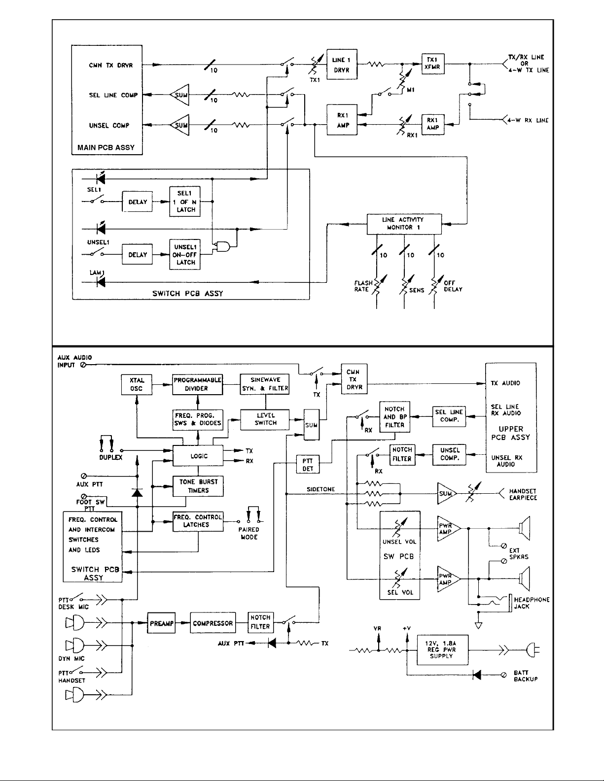
Line Selection: When one of the ten line-select
switches is momentarily pressed, it latches on
and releases any other latched line switch,
causing the console to switch to the selected
line. LED indicators show which line has been
selected. Receive audio from the selected line is
now heard from the selected-line speaker, and,
when thePTT switch is pressed,PTT command
and transmit audio are delivered to the selected
line.
When the TX ALL (simulcast) switch is
pressed, all lines are activated, all lines are
switched to the selected-line speaker, and, upon
PTT, all lines receive the PTT command and
transmit audio. When the TX ALL switch is
pressed again, all lines are deactivated and one
of the ten line switches must be pressed to
return to normal operation.
Selected Multiple-Line Operation: While the
GROUP SELECT switch is pressed, more than
one line can be selected and added to previously
selected line(s).
Timed Mute (C-5111 and C-5112 only): The
TIMED MUTE switch mutes “unselected”
audio from 0 dB to over 60 dB (internally
adjustable) for about 1 minute (or down to 2.5
seconds, internally adjustable).
Unselected-LineAudio:The ten unselected-line
switches operate in the push-on/push-off mode
and any combination of lines may be monitored
through the unselected audio channel and
speaker. The push-on/push-off RX ALL switch
may be used to monitor all unselected lines. (Any
and all lines active from line-select switches are
automatically switched to the selected-line
channel and speaker.)
Transmit-Line Monitor: For the four-wire
mode of operation with multiple consoles;
audio on the transmit line may be monitored in
the same manner as with two-wire operation.
Line-ActivityMonitors: Activity on any and all
of the ten lines is indicated by a flashing yellow
LED on the associated unselected switch.
Flashing continues for 2 to 10 seconds
(adjustable) after activity stops.
Parallel Single-Line Console Compatibility:
The C-5110B, C-5111, and C-5112 consoles are
compatible with parallel single-line consoles, such as
the Vega C-510C, which use the industry-standard
sequential-tone-signaling format. Operators with
these single-line consoles will have access only to the
base station to which their line is connected, while
C-5110B, C-5111, or C-5112 operators may access
up to ten of those lines. The C-5110B, C-5111, and
C-5112 are also compatible with the Vega C-516 and
C-1614 six-line tone-remote consoles.
Group-mute for C-5000 Series Consoles
Sometimes when you are using multiple
C-5000 Series Consoles in a multiple same
frequency transceiver environment. One
console can cause acoustic feedback from
another console due to overlapping receiver
coverage. Even though you maybe using
crossmuting, crossmute only mutes the channel
you are transmitting on and not adjacent
channels. We recommend ONE of the
following system wiring changes.
1. Jumper the following pins of P2 on the
solder side of the X-mute PCB to mute a
group of lines when PTT is pressed
Example: To mute lines 1, 2, 5, and 6 as a
group, short together P2-1, P2-2, P2-5 and
P2-6.
2.. At the punch block (clip or punch) together
the following pins of the 25pr telco cable to
mute a group of lines when PTT is pressed.
Example: To mute lines 1, 2, 5, and 6 as a
group, short together pins 1, 26, 3 and 28.
4
P2-1 Line 1 P2-6 Line 6
P2-2 Line 2 P2-7 Line 7
P2-3 Line 3 P2-8 Line 8
P2-4 Line 4 P2-9 Line 9
P2-5 Line 5 P2-10 Line 10
Pin-1 Line 1 Pin-28 Line 6
Pin-26 Line 2 Pin-4 Line 7
Pin-2 Line 3 Pin-29 Line 8
Pin-27 Line 4 Pin-5 Line 9
Pin-3 Line 5 Pin-30 Line 10

5
Figure 3
Upper and Switch PCB Assembly Block Diagram
Figure 4
Main PCB Assembly Block Diagram

Installation
The C-5110B, C-5111, and C-5112 ten-line
tone-remote consoles may be installed in any
location convenient to the operator. Exposure
to extreme dampness, temperature, and
radio-frequency energy should be avoided, to
insure maximum reliability and operating life.
The console is not designed to operate on lines
carrying direct current. If direct-current lines
are to be used, isolate the console with external
capacitors or with 600:600-ohm transformers
designed for the current involved.
The console has been factory-programmed for
single-console-per-line, two-wire half-duplex
operation and for +10-dBm/guard-tone output
into 600-ohm lines.
6
FIRSTCONSOLEONLY4#2THROUGHNCONSOLES
P38,P39 RX & TX P38, P39,
P40,P43 P37 R38 LOSS3P40,P43 P37 R38
1TO B1TO B1 1 0 dB TO B1TO A 1
2TO B1TO B11.5 kΩ20 dB TO B1TO A 1
3TO B1TO A 10 dB TO B1TO A 1
4TO B1TO A 11dB TO B1TO A 1
5TO B1TO A 12 dB TO B1TO A 1
6TO B1TO A 13 dB TO B1TO A 1
NUMBER
OF
CONSOLES
1 As shipped
2 For optimum line match and 0 dB loss
3Applies to all consoles
4“First” console should be at end of line when consoles are “chained”
Chart 1
Two-wire line programming
FIRSTCONSOLEONLY4#2THROUGH N CONSOLES
P38, P39 P37, P38,
P40,P43 P37 R38 R40 TXLOSS3P40,P43 P39
1TO A TO B1 1 1 0 dB TO A TO B1
2TO A TO B11.3 kΩ2 1 0 dB TO A TO B1
3TO A TO B12.7 kΩ2750 Ω20 dB TO A TO B1
4TO A TO A 1820 Ω20 dB TO A TO B1
5TO A TO A 11.0 kΩ21.0 dB TO A TO B1
6TO A TO A 11.1 kΩ21.9 dB TO A TO B1
7TO A TO A 11.2 kΩ22.7 dB TO A TO B1
8TO A TO A 11.5 kΩ23.4 dB TO A TO B1
NUMBER
OF
CONSOLES
1 As shipped
2 For optimum line match and 0 dB loss
3Appliestoallconsoles. RXloss is 0dBup to13consoles withoptimumR40 value
4“First” console should be at end of line when consoles are “chained”
Chart 2
Four-wire line programming

Disassembly, Setup, and Adjustment
Make sure that the line cord is unplugged
before opening. Access to internal controls and
jumpers is obtained by removing the four
screws on the side of the case and “folding” the
control panel forward. This procedure opens up
the entire unit for setup and maintenance.
Connect as many of the modular telephone
cords as will be used to the modular jacks on the
rear of the unit. Each line may be independently
programmed for two-wire (half-duplex only) or
four-wire lines, and for line-terminating or
bridging (for single or multiple consoles).
Proper termination impedance is maintained on
all lines regardless of line selection. Line drive
output, line input sensitivity, and TX monitor
sensitivity (four-wire lines only) are
independently adjustable.
Refer to the schematic diagrams and to the
designators printed on the PC board to identify
the programming and adjustments associated
with each line. The designators given in the
following programming and adjustment guide
apply to line “one” only. The same procedure,
using the individually associated designators,
should be followed for lines two through ten.
Control Console Test Procedures
Please refer to the following procedures to test
and readjust your control console.
Transmit Tone Test
Set Guard-Tone Level
1. Select Line 1
2. Ground TP5 on lower main board
3. Connect 600-ohm load, meter, and scope to
Line 1 otput (at Jack)
4. Press PTT
5. Adjust Line 1 transmit audio level control
TX1 (R90)onthe uppermainboard for a+10
dBm meter reading
6. For the other nine lines, in like manner,
adjust:
TX2 (R89) output level for Line 2, then
TX3 (R88), TX4 (R87), TX5 (R86),TX6 (R85), TX7
(R84), TX8 (R83), TX9 (R82), TX10 (R81)
Verify Function Tones
1. Ground TP6
2. Press F1 and verify 1950 Hz* at 0 dBm
3. Press F2 and verify 1850 Hz* at 0 dBm
4. Press F3 and verify 1750 Hz* at 0 dBm
5. Press F4 and verify 1650 Hz* at 0 dBm
*Or other DIP-switch-programmed frequency
Receive Audio Test
Selected Lines
1. Select Line 1 (white switch)
2. Connect scope and meter to J11-4
3. Apply a 1-kHz signal at 0 to Line input (at
jack)
4. Adjust RX1 (R70) input level control on the
upper main board for -8 dBm ±2 dBm
5. For the other nine lines, in like manner
adjust:
RX2 (R69) input level for Line 2, then
RX3 (R68), RX4 (R67), RX5 (R66), RX6
(R65), RX7 (R64), RX8 (R63), RX9 (R62),
RX10 (R61)
UnselectedLines
1. Select Line 1 (blue switch, with white switch
unselected)
2. Connect scope and meter to J11-3
3. Apply a 1-kHz signal at 0 toLine 1input(at jack)
4. Measure -10 dBm ±2 dBm
5. Repeat test for other nine lines
Line-Activity Monitor Test
1. Unselect all selected and unselected lines
(all LEDs “off”)
2. Apply a 1-kHz signal at -24 to Line 1 Input
(at jack)
3. Adjust LAM-sensitivity control R126 on
lower main board to light LAM 1
4. Adjust LAM control R119 for about 4
flashes per second
5. Adjust LAM off-delay control R124 for
about a 5-second off delay
6. Reduce signal to -28dBm; unit should not detect
7. Apply signal to other nine line inputs (at
jacks) and check LAM LED indications
7

Please Note...
In the “Upper PC Board Programming and
Adjustment” section, “line one” is often
used for examples. The same procedures
should be applied (”mirrored”) to lines two
through ten.
For example, for two-wire-line operation
you are told to set line one’s P38 and P40
to “B.” You should also set line two’s P34
and P36 to “B” (see schematic below) and
all the other lines (three through ten)
jumper plugs to “B.”
8
T9 R33
560
1200
8
560
R35
10K
10K :
:
3
BA
1
3BA
P36 3BA
1
P35
1R36
680
4
3
2
1
J9
P33
P34
31
A B
820
R34
T19
T10 R37
560
12008
560
R39
10K
10K :
:
3
BA
1
3BA
P40 3B A
1
P39
1R40
680
4
3
2
1
J10
P37
P38
31
A B
820
R38
T20
LINE 1
LINE 2

Upper PC Board Programming and
Adjustment
The designators given in the following
programming and adjustment guide refer to
line “one.” The same procedure, using the
individually associated designators, should be
followed for lines two through ten (for
example line one’s P37, P38, P39 are
equivalent to line two’s P33, P35, P36.
Two-Wire-Line Operation:P38 and P40 to
“B” per factory programming.
Four-Wire-LineOperation: P38, P40, and P43 to “A”.
Multiple Console Operation: Refer to Chart 1
(two-wire) or to Chart 2 (four-wire).
Line-Bridging Operation: When the line is
already terminated by non-Vega consoles, P37
and P39 to “A”.
Caution: Power must be connected during
setup and adjustment, and exposed hazardous
voltages exist in and near the power supply.
Line-Drive Adjustments: The console is
factory-adjusted for about +10dBmguard-tone
line level. The other tones and TX voice levels
are fixed relative to the guard tone. At +10dBm
guard tone, the function tone is 0dBm, the PTT
tone is –20 dBm, and voice level is about 2.4
Vp-p.
Line level should be measured with the leased
line connected by touching the top of P38 and
P40 with the meter probes (two-wire line). For
ease of adjustment, jumper TP5 to on the lower
PC board and depress the F1 switch. This
causes a continuous guard tone to be generated.
A continuous PTT tone is generated without
jumpers by pressing and holding the PTT
switch. Measurement of voice level is not
recommended except with the use of an
oscilloscope. TX1 (R90) allows adjustment of
line drive.
All level controls associated with an unused
line (e.g., TX1, RX1, and M1) should be
adjusted to their minimum setting.
Input Level Adjustments: RX1 (R70) allows
adjustment of input sensitivity. This control
should be adjusted to slightly above the
threshold of compression with typical voice
signals on the line. Sensitivity should not be
increased beyond that required by line loss,
because increased sensitivity amplifies line and
background noise during pauses in voice traffic
without increasing the level of voice
recognition.
Line-Activity Monitor Adjustments: LAM
adjustments affect all ten circuits. Sensitivity is
adjusted by the LAM SENS control R126. Off
delay is adjusted by LAM OFF DELAY control
R124. Flash rate is adjusted by LAM FLASH
RATE control R119.
Main (Lower) PC Board Programming
and Adjustments
Most adjustments and programming (except for
four transmit audio output level jumpers,
primarily for factory test applications) on the
main (lower) PC board are accessible without
removing the upper PC board.
Microphone Sensitivity Adjustment:Microphone
sensitivity has been factory-adjusted to cause
about 10 dB of compression from a typical male
voice about 10 inches from the desk microphone.
MIC SENS control R18 allows adjustment if
desired. Microphone sensitivity should not be
advanced beyond that required for the
operator’s voice, because increased sensitivity
only causes an increase in background noise
during speech pauses, without increasing the
level of the transmitted voice. When an
optional dynamic microphone is used, P1 may
be move to A for high-impedance dynamic
microphones.
9

Optional Handset Adjustments
Earpiece volume level is adjusted by
EARPIECE LVL control R134. Selected,
unselected, and sidetone audio is summed into
the handset earpiece. Earpiece volume level is
unaffected by the front panel volume controls.
Handset microphone sensitivity is adjusted by
the MIC SENS control R18 (same as the desk
microphone).
Duplex Operation
The console is not designed for duplex
operation over two-wire lines. If all lines are
four-wire, move DUPLEX jumper plug P3 to A
for duplex operation. In this mode of operation,
the receive audio circuits (except TX monitor)
are active at all times; however, the line-drive
circuits are active only during PTT and
intercom.
The console is not designed for a combination
of duplex operation on some four-wire lines
and simplex operation on other two-wire or
four-wire lines. In the duplex mode, all
lines
must be four-wire duplex, unless a modification
is made. This modification involves the
installation of a relay to switch the
“simplex/duplex” jumper when particular lines
are selected. Simulcast operation is not possible
with this modification.
Timer Adjustments
Guard-tone and function-tone durations are
factory-adjusted for 130 ms and 40 ms,
respectively. If other durations are desired,
adjust the guard-tone duration with GUARD
TONE control R132 and the function-tone
duration with FUNCT TONE control R133.
10
FUNCTION
TONE
FREQUENCY
S1, S2, S3, S4
SWITCH POSITION PERCENT
ERROR
12345678
1950 Hz 00010001±0.000
1850 Hz 00011001–0.106
1750 Hz 00100010–0.265
1650 Hz 00101011+0.213
1550 Hz 00110110+0.230
1450 Hz 01000011±0.000
1350 Hz 01010001+0.213
1250 Hz 01100010+0.088
1150 Hz 01110110–0.053
1050 Hz 10000111–0.265
950 Hz 10010101–0.124
850 Hz 10100110+0.195
Other function-tone frequencies may be
obtained by using the formulas below, where
f=function-tonefrequency,and
N = bi nary value of switch po si tions 2 through 8
f=282,750/(N+128)whenswitchposition1 is off
f=141,375/N+128)whenswitchposition1ison
N= (282,750/ f)– 128when switchpo sition 1
is off (pro gram to the near est whole number)
If the desired N is greater than 255, switch
position 1 must be on, and the following
formula used:
N = (141,375 / f) – 128,
andprogramtothenearestwholenumber.
Although the maximum frequency range is
from 554.4 Hz to 2209 Hz, the maximum
frequency range used in any one system
must not exceed 3 to 1 minus 100 Hz. This is
dueto thestrong thirdharmonic generatedby
typical decoder limiters at the base station.
(Exception: Model D-342C-type decoders do
not have this limitation.)
f/2 64 32 16 8 4 2 1
BINARY VALUE
0=SWITCH OFF
1=SWITCH ON
Chart 3
DIP-switch settings for F3 and F4 function-tone frequency programming

Notch Tuning and Notch Outphase Control
Notch tuning and notch outphasing has been
factory-adjusted and sealed for the best
2175-Hz notch. Adjustment is not required.
Auxiliary Audio Input and PTT
Auxiliary audio signals connected to TB1-1,2
should be externally level-adjusted after all
line-drive controls have been set. When a
line-drive control has been set for a 0-dBm
function tone, –2 dBm into the auxiliary input
will drive the line at about 0 dBm. An external
switch connected to the AUX PTT input
TB1-3,2 causes tone burst, PTT tone, and
auxiliary audio line drive, but microphone
audio is disabled.
Footswitch PTT
An external switch connected to TB1-12,2 has
exactly the same effect as pressing a PTT
switch.
Tone-Burst Frequency Programming
Console tone frequencies are factory-programmed
by diodes to 2175 Hz (PTT/guard) and to 2050 Hz
(monitor), and DIP-switched programmed to 1950
Hz (F1), 1850 Hz (F2), 1750 Hz (F3), and 1650 Hz
(F4). Refer to Chart 3 to program F1, F2, F3, and
F4 to other frequencies.
Paired F1-F2 and F3-F4 Operational Mode
To change frequency-select mode of operation
from 1-of-N to paired mode, change PAIR
MODE jumper plug P2 to B. In this mode, one
of the F1-F2 pair remains latched on and one of
the F3-F4 remains latched on. F1 and F2 tone
bursts occur from PTT, F1, or F2 switch
operation, while “F3” or “F4” tone bursts occur
only from “F3” or “F4” switch operation. A
typical use of this paired mode is F1 and F2 for
frequency control and F3 and F4 for scan up
and scan down of the remote radio.
Defeat F2, F3, and/or F4
Any of the frequency-select switches may be
defeated by reprogramming the unwanted-frequency
switch to the same frequency as one of the other
frequency switches.
Special Uses for F2, F3, F4
One of the many possible uses for F2, F3, and
F4 with single-frequency radios is selective
control of up to four base-station radios on a
single leased line. The four radios could all be
at the same site or 50 miles apart. In a
three-station system on the same line, one
frequency can be used for simulcast.
Headphones
A stereo headphone jack has been provided so
that selected audio is heard in one ear and
unselected audio in the other. Use of this jack
automatically disconnects the console speakers.
Headphone audio level adjustment is obtained
from the front-panel volume controls. NOTE:
Monaural headphones are not recommended,
because only selected audio is heard; a
monaural plug shorts the output of the
unselected-audio amplifier to ground (through
a resistor).
External Speakers
Normally, if used, a pair of 8-ohm external
speakers is connected to TB1-6,7 and
TB1-9,10. This connection drives the external
speakers with power equal to the internal
speakers. The connection of a single 8-ohm
external speaker to TB1-6,9 drives the external
speaker at a –6-dB level from the selected audio
channel and a –6-dB level from the selected
audio channel. It should be noted that local
audio from or intercom will not be heard from
the external speakers.
Battery Backup or DC Supply Operation.
A 12-volt (13.8-V nominal) vehicular-style
battery connected to TB1-5,4 will provide
backup in case of power failure.
11

Special Transmit Audio Levels
Assuming that the transmit audio level has been
adjusted to 0dBm(function-tone and microphone
audio) for a particular line (with the appropriate
line output level control on the upper main PCB
and MIC SENS control R18 on the lower main
PCB, which results in +10 dBm guard-tone and
–20 dBm continuous PTT tone output), the
following levels can be changed (for test or
other applications) by moving the designated
jumpers on the lower main PCB:
Microphone Audio: Change from 0 dBm to –6
dBm by moving P12 from B to A.
GuardTone: Change from +10 dBmto 0 dBm
by moving P11 from A to B.
Function Tone: Change from 0 dBm to –10
dBm by moving P10 from A to B.
Continuous PTT (Hold) Tone: Change from
–20dBmto –30dBm bymovingP9fromAtoB.
The above jumpers on the lower main PCB are
accessible only by first removing the upper
main PCB.
Switch PC Board Programming
TX ALL Defeat
Only one frequency-select tone burst at one time
is possible; therefore, when multifrequency
radios are used, TX ALL will not simulcast to
everyone at the same time. For this or other
reasons it may be desirable to defeat TX ALL.
This is done by moving the DEFEAT TX ALL
jumper plug P23 to “B”.
Line 1 to 10 Defeat
For unused lines and for “lockout” of transmit
on certain lines from certain parallel consoles,
any of the ten line-select switches may be
defeated. This is accomplished by moving the
appropriate jumper plug (P11 to P20)
associated with the line to be defeated from “A”
to “B”. Note that the operator of the console
“locked out” from transmitting on certain lines
may still listen to all audio on those lines by
using the unselected line switches.
Unselected Line 1 to 10 Defeat
For unused lines and for “lockout” of
unselected audio on a certain line, move the
appropriate jumper plug (P1 to P10) associated
with that line from “A” to “B”.
NOTE: Defeat of individual line-activity-monitor
LEDs has not been provided. For a 100% lockout
of a certain line to certain consoles, simply delete
the line connection to those particular consoles and
treat as an unused line.
Theory of Operation, Control Panel
Referring to the control-panel PCB schematic,
operation of the line-1 switch S1 applies a high
to the set input of the line-1 latch at U7-4
through the 20-ms-delay shift register U8-1,15
and RN10-2,1. Switch S1 operation also
applies an undelayed high to the reset input of
the line-1 latch at U7-3 through DN1-5,1. Since
the reset inputs of all 10 latches are connected
to a common bus, S1 operation resets any
latched circuit on the bus, including the line-1
latch U7A. However, 20 ms after S1 operation,
the line-1 latch set input goes high, and, since
set dominates when both set and reset inputs are
high, line-1 Q at U7-2 goes high, enabling
line-1 analog gates on the upper-main PCB
assembly. These analog gates connect the
line-1 driver to the TX circuits and connect the
line-1 RX circuit to the selectedRXaudio input
on the lower-main PCB assembly.
The nine other line-select switches S2 through
S10 operate identically to S1.
TX ALL
The TX ALL switch S11 applies a high to
U20-11 through U9-10,6, clocking U20-12
low, which causes U16-15 and the TX ALL
common to go high. This high is applied to all
line-select switch contacts through RN3 or
RN4, setting all line-select latches in the same
manner as described for single-switch
operation.
When the TX ALL switch is pressed again,
U20-12 is clocked high, U16-15 and the TX
ALL line go low, the reset line goes high
through C3 and DN3, and all line-select latches
are reset.
12

Group Select
When group select switch S32 is pressed, the
reset inputs of all ten line-select latches are
pulled low through CR4. When these reset
inputs are held low, additional line-select
latches may be set by pressing line-select
switches without reset of previously set latches.
Upon release of the group select switch,
pressing any line-select switch will again reset
all latches except the one pressed.
Individual PTTSwitch PCB
Pressing the line 1 PTT switch S1A applies a
high to the junction of R26 and CR6 on the
switch PCB schematic. That path is through
CR1 and P241 on the VC/PTT PCB and P25-11
on the switch PCB. This high activates the
upper PCB analog gate U10 at pin 5 through
R26 and P22-2 on the switch PCB and P42-2 on
the upper PCB. An audio path from TX
common to the line 1 driver circuit now exists.
The high from S1A on the VC/PTT PCB also
lights LED S1B and causes transistor Q1 to
conduct through S1B, RN3A, and R25. The
collector of Q1 connects to the PTTswitch S30
on the switch PCB through P2-23 on the
VC/PTT PCB and P25-23 on the switch PCB.
The low at P25-23 activatesPTT through diode
CR16 and disables all line-select latches U7,
U12, and U21 at their pin 5 output-enable
inputs. PTT is therefore applied to line 1 only
and, upon release of the line 1 PTT switch, the
line(s) previously latched with a line-select
switch are again enabled. R47, R48, CR17, and
C12 provide a short time delay upon release of
the instant-PTT switch.
Individual Line Volume Controls
The individual line volume-control signal path
for line 1 is from U24-7 on the upper PCB
through R133 and P44 to P1-1 and volume
control R1 on the VOL/PTT PCB. The control
terminal of U1A connects to P2-1 and to P25-1
on the switch PCB. This connection causes a
high at U1A-13 whenever unselectedRXline 1
is on. The audio path is now from R1-2 through
U1A-1,2, RN1-2,1, U3-10,11, R23, P1-12 to
the upper PCB, P44-12, and U32-2, the input of
the unselected RX summing amplifier.
Timed Mute
The timed mute switch S11A, when pressed,
triggers timer U5A at U5-5 through C4 and
R34. U5-7 goes low, disabling U3C, and U5-6
goes high, enabling U3D. The audio path is
now through the mute level from 0 dB to over
60 dB. MUTE TIME control R29 is factory set
to about 1 minute, but may be adjusted as
desired down to under 2.5 seconds. The mute
timer may be reset at any time during the timing
cycle by pressing S11A again. The reset path is
from S11A through C6 to U5-3. Upon reset,
U5-5 is held high for about 10 ms through C5
and CR12, preventing aretrigger. LED S11B is
energized during mute from U5-6 through Q2.
Unselected Line Receive Circuits
Operation of the RX1 switch S12 causes a high
at U11-1 and, after a 20-ms debounce delay,
U11-15 goes high, clocking flip-flop U1A high
at U1-1. Release and reoperation of S12 clocks
U1-1 back to low due to the U1-2 (Q) to U1-5
(D) connection. The unselected RX circuits
therefore operate in a push-on/push-off mode.
When the U1-1 Q is high, this high is applied to
U2-8 through U2-5,4 and RN2-2,1. If U7-6 is
low (line 1 has not been selected for TX), a high
appears at U2-10, which enables the RX1 LED
(red) through U15-1,18 and the unselected
line—line-1 analog gates on the upper-main
PCB assembly.
If line 1 has been selected for TX, U7-2 and
U2-9 are high and no enable to the
unselected-line analog gate or the RX1 LED
takes place. (The selectedRXchannel has been
enabled by the high at U7-2.)
The second (yellow) LED in S12 (LAM1) is
driven from the line-activity-monitor circuit on the
upper-main PCB assembly. (See “Line-Activity
Monitor” under Operation and Controls.)
13

The nine other unselected RX switches S13
through S21 operate identically to S12. TheRX
ALL switch S22 operates flip-flop U20A in the
same manner as the other ten switches, but the
Q output at U20-1 connects directly to its LED
driver U16-3,16 and to the common bus to all
OR gates. A high at U20-1 therefore enables all
unselected RX outputs except those disabled by
a selected line or by one of the unselected RX
defeat jumper plugs P1 through P10. These
defeats operate by holding one input of a
negative-input AND gate high.
DebouncerICs U8, U11, U13, U19
A single capacitor C7 at U19-7,9 determines
the delay associated with all of the debouncers.
The oscillator-out pin 9 of U19 is internally
connected to all U19 sections and to the set
input of U21C and U21D used as buffers.
U21D drives the oscillator input pin 7 of U8 and
U13, and U21C drives the oscillator input pin 7
of U11. Thus, the input-to-output delay of all
debouncersis directly proportional to the value
of C7.
Other Switches, LEDs, Pots, and Speakers
(See Lower-Main PCB Assembly.)
Line Drive and Line Receiver Audio
Circuits (Upper-Main PCB Assembly)
Referring to the upper PCB schematic sheet 1,
line-1 receive audio signals are applied to
U24-6 through T20, RX1, control R70, and
RN10-1,2. If line 1 is configured for 4-wire line
operation, transmit or intercom audio signals
from parallel consoles are also applied to U24-6
through T10, M1 control R60 (TX monitor 1),
U10-1,2, and R80. This signal path is disabled
during local TX by a low at U10-13. Diodes
CR5 and CR10 connected to transformers T10
and T20 are for transient protection and are
inactive during normal operation.
Receive audio signal buffered output at U24-7
is applied to the LAM1 (line-activity monitor 1)
input at U31-13 through C20. At idle,
U31-14,10,8 are high and the line 1 LED
(LAM1) on the switch PCB is off. When a
line-1 audio peak exceeds the bias voltage at
U31-13, U31-14 goes low, pulling U31-10,8
low, energizing the LAM LED in the
unselected line-1 switch, and charging
capacitor C44. A low from U31-14 is
momentarily applied to U31-12 through C30
and CR20. This positive feedback stretches
short above-threshold peaks into longer output
pulses. When line activity ends, C44 discharges
through R115 until the voltage at U31-10
exceeds the bias voltage at U31-9. U31-8 goes
high and the LAM1 LED goes off.
The bias voltage at U31-9 is obtained from the
“A” line, which is connected to all LAM
circuits. This bias voltage is generated at “H”
on sheet 2 and fluctuates between 0 and 3Vdc
at
a rate determined by R119, the flash-rate
control. When the “A” line is at 0 V, all LAM
LED drivers are off-biased regardless of the
charge on the off-delay capacitors such as C44.
All active LAM LEDs therefore flash at the
same rate. U28-1,2,3 is the flash-rate oscillator
which is biased to generate a 50% DF
(squarewave) output.
The “B” line connected to R115 and the other
LAM circuits provides a variable DC voltage
source for capacitor C44 discharge. C44
discharges to the threshold bias of U31-10 at a
rate determined by this “B”-line voltage;
therefore, LAM off-delay is also determined by
thisvoltage. The“B”-line voltages generatedat
U8-7 (“J”) and is varied by the off-delay control
R124.
LAM sensitivity is varied by the variable
voltage on the “C” line, which is generated at
U28-8 (“K”) and is varied by the LAM SENS
control R126.
TX audio signal from the main PCB is
connected to the “F” line, which, when U10-5 is
high from the Q output of the selected line latch
on the switch PCB, drives line 1 through
U10-3,4, TX1 level control R90, U25-2,3, R59,
and T10.
14

When selected line 1 is on, RX audio signal
from line 1 at U24-7 drives the selected-line
compressor on the main PCB through U10-9,8,
RN5, the “E” line, U32-6,7, and J11-4.
When the unselected line-1 switch is on and the
selected line-1 switch is off audio signal from
line 1 drives the unselected-line compressor on
the main PCB through U10-10,11, RN5, the
“D” line, U32-2,1, and J11-3.
The circuits of all ten lines are identical and,
therefore, operation of the other nine lines is the
same as line 1.
Main PCB Assembly
Referring to the main PCB schematic, crystal
oscillator Y1 and U13-3,6 drive an 8-bit
programmable divider U23. The most
significant bit at U23-14 is high through R19
and R20, causing the programmable division
range to be 255 to 128. This provides an output
at U23-1 of from 11,088 kHz to 22.09 kHz.
U7A is a programmable divide-by-two counter.
This provides drive to U4 of from 5.54 to 22.09
kHz. U4 is a divide-by-ten counter used to
synthesize a sinewave. The output of U4 is
therefore 554 Hz to 2209 Hz. The synthesized
sinewave has a strong tenth harmonic which is
eliminated at the lowpass filter output U15-1.
At idle the crystal oscillator is disabled by a
high at U13-4. Going off-hook, or operation of
the MON, F1, F2, F3, or F4 switches triggers
the guard-tone timer U12C, which enables the
crystal oscillator and the “+10 dBm” gate at
U9-5. The 2175-Hz programming diode CR19
is enabled by the timed-out state of the
function-tone timer U12A. The guard-tone
signal from U9-4 drives the upper PCB TX
circuits through R36, U15-6,7, and P5-1.
Timeout of the guard-tone timer after 130 ms
triggers the function-tone timer at U12-3. U12-13
goes high, which enables the “0 dBm” gate at
U9-13, disables the 2175-Hz programming diode,
and enables one of the function-tone-programming
DIP switches S1, S2, S3, or S4, depending upon
which frequency-select switch has been depressed.
A “0 dBm” function-tone-frequency sinewave
therefore appears at the TX output P5-1.
Timeout of the function-tone timer after 40 ms
ofoperationreturnsconditionstotheidlestate.
PTT-switch operation causes the same
sequence of operation as above, except that
upon function-tone timeout, the crystal
oscillator remains enabled and the “–20 dBm”
2175-Hz PTT tone is conducted to output pin
P5-1 through R22 for as long as thePTT switch
is held.
In addition to triggering the guard-tone timer,
going off-hook or monitor-switch operation
sets the monitor latch U12D, which then lights
the monitor LED through U18A-1,16. Upon
function-tone-timer operation, the monitor row
of programming diodes (CR20, CR21) is
enabled and the F1, F2, F3, and F4
programming DIP switches are disabled. Upon
function-tone-timer timeout, the monitor latch
is reset through C11 and U8-13,11 and
conditions return to the idle state.
Operation of one of the frequency-select
switches (F1, F2, F3, F4) sets one of the U10
latches and applies reset logic to all four of the
latches through DN1 and RN1. When a U10
latch is simultaneously set and reset, set
dominates and Q goes high. Upon release of the
frequency-select switch, the set input of U10
remains high for about 5 us longer than the reset
input, due to the charge on one of the 0.01-mF
capacitors C24, C25, C26, or C27, the
associated latch remains set, and whichever of
the other latches previously set has now been
reset.
A frequency-select LED is energized through
U18 and one of the U6 inputs or U14-11 is high
from a set latch U10. When the function-tone
timer is triggered, one of the U6 outputs or
U14-10 goes high, enabling F1, F2, F3, or F4
programming.
When the paired mode of operation is
programmed (P2 to B), U7B-10 and U7B-8 are
low at idle. F3 or F4 switch operation applies a
set pulse to U7B-8 through CR5 or CR6, C7,
U3-13,12, and U2-1,3. Simultaneously, the
guard-tone timer is triggered, which applies a
reset pulse to U7B-10 through C95, U3-5,6,
and U2-12,11. The set pulse is 10 times longer
than the reset pulse and the set pulse prevails.
15

Thus, only F3 or F4 programming is enabled
during function-tone operation. F1 or F2 switch
operation generates only the reset pulse, which
resets U7B, if set, and enables only the F1 or F2
programming. PTT-switch operation also
generates only the reset pulse, which insures
that only F1 or F2 programming is enabled
during function-tone-timer operation. Paired-mode
programming also activates all sections of U5,
which connects U10 latch Q to the reset input of
the other latch of the pair. If one of the pair of
latches is set, the other consequently is reset.
In the 1-of-N mode, upon power up, the F1
latch is set with a 470-ms pulse at U10-12 by
C28 through CR4. A 47-ms set pulse is also
applied to the F4 latch by C8 through U3-11,10
and CR2. A 100-ms reset pulse generated by
C13 is applied to all latch reset inputs. Only the
F1 latch, therefore, is set.
In the paired mode, the C13-to-latch-reset-input
path is short-circuited effectively by the
activated analog gates U5. Both the F1 and F4
latches receive a set pulse during power up and
both become latched.
Main PCB Receive Circuits
Selected RX signal from the upper PCB is
applied to the selected RX compressor at
U25-15 and U25-11. Maximum gain of the
compressor (actually an automatic-level-control
or ALCcircuit) is determined by the bias voltage
on capacitor C66. This bias voltage is set by
R73. Input signals are full-wave rectified within
U25 and applied to C66. When the rectified
input signal exceeds the bias set by R73, it
charges C66 to a higher voltage, which lowers
stage gain and thus maintains a near-constant
average output signal at U25-10 for all signal
inputs above the bias threshold.
Output signal at U25-10 is connected to peak
detector U22-8,9,10,12,13,14. High-level,
short-duration peaks cause output at U22-8 or
U22-14, which quickly charges C66 through
R61 and CR17, and reduces U25B stage gain.
Output signal at U25-10 also drives selectedRX
2175-Hz notch/bandpass filter through U16-8,9.
Bandpass output at U30-8 is amplified and
rectified by the U21-8,9,10,12,13,14 circuit.
Detector output at U21-14 lights the TX LED
through U18F whenever parallel console PTT
tone is present on the selected line. The TX LED
is also energized by PTT-switch operation
through another path.
Bandpass-filter output is summed with
unfiltered signals at U30-2, causing a sharp
2175-Hz notch to appear in the summed output
at U30-1 when the two signals have been
adjusted for equal amplitude by R126 and for
180° phase differential by R124.
Notched output signals from U30-1 are
conducted through U26-4,3 and R75 to the high
side of the selected RX volume control on the
switch PCB and then to the selectedRXspeaker
through U19, a power-amplifier bridge. Analog
gates U16-8,9 and U26-4,3 are disabled during
PTT, intercom, and tone burst, unless the unit
has been programmed for duplex operation.
The unselected audio circuits are identical to
the selected audio circuits, except that the PTT
tone detector has been deleted.
Audio from selected RX, unselected RX, and
TX (sidetone) is summed by U31-1,2,3 and
applied to an optional handset.
Audio from the above sources is also summed
by U31-5,6,7 and applied to an optional
VU-meter circuit.
Insertion of a phone plug into the headphone
jack disconnects both speakers from the power
amplifiers. U27-1,2,3 and U26-11,10 enable
sidetone during headphone use.
16

Main PCB Transmit Circuits
During mic-PTT or intercom, the audio signal
path is from a from a micinput such as the desk
mic through C2, U1-2,1, and C50 to the TX
compressor input at U24A-2. This circuit is
identical to the selected RX compressor
previously described. TX compressor output at
U24-7 is applied to the TX notch filter U28
through U16-11,10. TX notch filter U28 is
identical in circuit and operation to the selected
RX filter previously described. The TX signal
path from the TX notch output to the
upper-PCB TX circuit is through U9-8,9, R37,
U15-6,7, and P5-1. Analog gates U16-11,10
and U9-8,9 are enabled only during PTT or
intercom.
If a DTMF or paging-encoder option is
installed, connection is made to P13-1,2,3,4,5,6
on main PCB.
Alert-Tone Generator
Alert-switch operation enables PTT and the
1-kHz sinewave oscillator U27-8,9,10. This
oscillator consists of a multiple-feedback
bandpass filter with a Q of about 7.5 and, when
enabled, a positive-feedback path to cause
oscillation. When U26-13 is high, the
positive-feedback path is from U27-8 through
R89, U26-2,1, and R74. When oscillation
amplitude reaches the threshold of diode CR18
and CR22 conduction, loop gain is decreased
and oscillation amplitude is stable at a level
lower than U27-8 clipping.
Technical Assistance
Vega products are engineered to meet your
requirements of performance, reliability, and
compatibility. Technical assistance is offered
by correspondence or telephone, should it be
required, to assure your satisfaction.
Warranty (Limited)
All Vega signaling products are guaranteed
against malfunction due to defects in materials
and workmanship for three years, beginning at
the date of original purchase. If such a
malfunction occurs, the product will be
repaired or replaced (at our option) without
chargeduring thethree-yearperiod,ifdelivered
to the Vega factory. Warranty does not extend
to damage due to improper repairs, finish or
appearance items, or malfunction due to abuse
or operation under other than the specified
conditions, nor does it extend to incidental or
consequential damages. Some states do not
allow the exclusion or limitation of incidental
or consequential damages, so the above
limitation may not apply to you. This warranty
gives the customer specific legal rights, and
there may be other rights which vary from state
to state.
Claims
No liability will be accepted for damages
directly or indirectly arising from the use of our
materials or from any other causes. Our liability
shall be expressly limited to replacement or
repair of defective materials.
17

18
Specifications
PanelSwitch-SelectableLines: ........10
Each Line Input and Output Impedance
Two-Wire: 600 Ωor 2 kΩ, jumper selectable,
transformer isolated
Four-Wire TX Line: 600 Ωor 2.6 kΩ, jumper
selectable, transformer isolated
Four-Wire RX Line: 600 Ωor 8 kΩ, jumper
selectable, transformer isolated
Each Line Input Level:
-30 dBm to +15dBm, adjustable
Each Line TX Monitor Input Level
(four-wire line):
-15 dBm to +15 dBm, adjustable
Each Line Output Level:
-20dBm to +12 dBm intoa 600-Ωline, adjustable
Audio Compression
(selected and unselected receive and transmit):
Less than 3 dB change in output level for a 30-dB
change in input above threshold
Distortion:
2% maximum at full compression
Hum and Noise:
50 dB below operating levels
Speakers (two):
4in, 8 Ω, heavy-duty, waterproof
Amplifier Power (each):
2.5 W minimum at 2%THD intoan 8-Ωload; 5 W
minimum at 2% THD into a 4-Ωload (internal
speakerplusanexternal8-Ωspeakerin parallel)
Sidetone Level (optional handset or earphones):
About 25 dB below receive level
Optional Handset Earpiece Level:
Adjustable preset level independent of speaker
volume controls
Audio Frequency Response:
±1.5 dB, 300 to 3000 Hz, except at the transmit
tonenotchfrequency
Line Activity Monitors
Sensitivity: ...-30to -5dBmline,adjustable
OffDelay: ........1.5 to 10 s, adjustable
FlashRate: .......2to20Hz,adjustable
Notch Filter (three):
2175 Hz; 45-dB typ attenuation
Tone Frequencies and Accuracies:
PTT/Guard, 2175 Hz, 0.01%; MON, 2050 Hz,
0.1%; F1, 1950 Hz, 0.01%; F2, 1850 Hz, 0.2%;
F3, 1750 Hz, 0.3%; F4, 1650 Hz, 0.2%. (F1, F2,
F3, and F4 frequencies are DIP-switch
programmable.)
Burst-Tone Duration:
Guard, 130 ms; function, 40 ms; both adjustable
Operating Temperature Range: 0 to +50°C
LED Visual Indicators:
10 selected line, 10 unselected line, 10
line-activity monitor, 2 PTT, 10 instant PTT
(C-5111 and C-5112 only), TX, TX ALL, ALERT,
TIMED MUTE (C-5111 and C-5112 only),
GROUP SELECT,RX ALL, IC, MON, F1, F2, F3,
F4)
Line-Selection Switches:
10 in 1-of-N or “accumulate” modes, plus TX ALL
(simulcast)
Unselected Line-Selection Switches:
10 push-on/push-off plus RXALL, with automatic
switch to selected-line audio channel upon
selection
Instant-PTTSwitches (C-5111 and C-5112 only):
10 momentary
Volume Controls:
Selected master, unselected master, 10
individual unselected (C-5111 and C-5112)
Operating Modes:
Simplex(half-duplex) withtwo-wirelines; simplex
or full-duplex with four-wire lines
Line Interface:
Modular cords for two-wire or four-wire line, in
line-terminating or line-bridging modes, jumper
selectable
AccessoryJacksandTerminals:
Desk mic, handset, dynamic microphone,
earphones, auxiliary PTT, auxiliary audio,
footswitch, battery backup, external speakers
Power Requirements:
120/240 Vac, 50/60 Hz, 35 W maximum, or 12 to
15 Vdc at 1.8 A maximum
Size:
C-5110B: 16.2 in (41.1 cm) W x 12.7 in (30.7 cm)
D x 5.91 in (15.0 cm) H; C-5111:16.5in(41.9cm)
W x 14.5 in (36.8 cm) D x 9.0 in (22.9 cm) H;
C-5112: 21.25 in (53 cm) W x 13.75 in (34.9 cm)
D x 9 in (22.9 cm) H
Weight:
C-5110B: 19.5 lbs (8.85 kg); C-5111: 22 lbs (10
kg); C-5112: 24.5 lbs (11 kg) (approximately)

C-5110B Parts List
Part No. Description Qty CKT SYM
010-1105 10-LINE TONE CNSL
011-0091 TOP ASSYC-5110B ....................1
098-0344 MAN INST C-5110B ....................1
674-0230 CORD AC POWER 3 BLADE ...............1
674-0239 CORDTEL MDULR 7’ PLG-PLG.............10
817-0458 CARTON FOR C5XXX...................1
817-0459 STYRENE FOR C5XXX ..................1
011-0091 TOP ASSY
012-0048 PCB ASSYC-5112 SWITCH ................1......1
012-0049 PCB ASSYC-5110B UPPER ................1......2
012-0050 PCB ASSYC-5110B LOWER ...............1......3
021-6618 GRILLE SPK C-5110 CONS ................2......4
021-6650 PLATE MTG SW C-5112 CONS..............1......5
021-6651 PLATE ACRYLIC C-5112 CONS ............. 1......6
021-6661 PLATE CONN #1 C-5112 CONS..............2......7
021-6675 BASE C5110B CONSOLE ................. 1......8
021-6676 PANEL TOP C-5110B CONSOLE ............. 1......9
021-6677 PLATE ACRYLIC C-5110B ................1...... 10
021-6679 PLATE REAR C-5110B...................1...... 11
021-6680 COVER SIDE C-5110B...................2...... 12
031-0219 TEST SPEC C-511OB....................0...... 13
071-0542 SCHEMATIC C-5110B SWITCH..............0...... 14
071-0543 SCHEMATIC C-5110B UPPER ..............0...... 15
071-0544 SCHEMATIC C-5110B LOWER ..............0...... 16
161-0564 LED RED 250 MTG 6” WIRES...............1...... 17
249-0151 SPEAKER4”SQ 4W WP..................2...... 18
261-0302 FUSE HLDR 3AG PANEL MTG..............1...... 20
261-0323 FUSE 1. 25ASLOBLO 3AG 250V ............. 1...... 19
286-1742 CONN AC POWER 3 BLADE ...............1...... 21
286-1783 CONN PIN CONTACTS ..................3...... 22
286-1874 PLUG 3 PIN POLARIZED ................. 1...... 23
286-1900 CONN RBN34 POS IDCPOL ...............2...... 24
286-1901 CONN RBN40 POS IDCPOL ...............2...... 25
286-1903 PLUG PWRDC 2. 5MM S-TERM ............. 1...... 26
407-0119 XLR 3 PIN FEM CH MT..................1...... 27
450-0038 PS 12V 3.5 MUL S-40-12 ..................1
460-0317 FOOT RUBBER BLACK..................4...... 29
460-0321 GROMMET 5/16 DIA RBR BLK..............1...... 30
475-1410 SLDER LUG #6 INSULATED ...............2...... 51
518-0115 WASH LOCK 6 INT ....................6...... 31
527-0134 SCREW FH4-40 X 3/8 OVAL ...............2...... 32
527-0266 SCRFH 100 8-32 X 3/8 BLK ................6...... 33
528-0022 SCREW PH 6-32 X ¼ ....................9...... 34
528-0239 SCREW PH 4-40 X 3/8 BLK ................7...... 35
528-0242 SCREW PH 6-32 ¼ NYLOCK ...............13 ...... 36
528-0278 SCREW PH 4-40 X ¼ BLK................. 4...... 37
536-0357 NUT TINNERMAN ¼DIA ................. 1...... 38
538-0075 NUT KEP 4-40 .......................11 ...... 39
538-0076 NUT KEP 6-32 .......................17 ...... 40
550-0300 KNOB 29MM ........................2
550-0301 CAP 29MM ......................... 2
19
This manual suits for next models
2
Table of contents
Other Telex Recording Equipment manuals
Popular Recording Equipment manuals by other brands

Siemens
Siemens IAQ6-1 Installation instruction

V-GREAT
V-GREAT VG-6728 installation manual

OSCILLATOR DEVICES
OSCILLATOR DEVICES Garbage Collector 1.0 manual

Roland
Roland Realtime Arranger RA30 owner's manual

Dr. Neuhaus
Dr. Neuhaus ZDUE-GSM-PLUS-V installation instructions

Oehlbach
Oehlbach MediaCenter D7-H manual