AV TOOL CSC-1600HD User manual

OPERATIONS MANUAL
CSC-1600HD Video Scaler

2

3
Table Of Contents
Section Page
1 INTRODUCTION …………………………………………………………………...4
1.1 Getting the Best Results………………………………………………………...4
2 SPECIFICATIONS………………………………………………………………… 5
3 CHECKING THE PACKAGE CONTENTS……………………………………… 5
4 CONNECTING THE HARDWARE………………………………………………..6
4.1 Rack Mounting…………………………………………………………………...6
4.2 Connecting the Video Inputs……………………………………………………6
4.3 Connecting the Video Output…………………………………………………..6
4.4 Connecting the AC Power………………………………………………………6
5 FRONT PANEL CONTROLS…………..………………………………………….7
5.1 Input Selection….………………………………………………………………..7
5.2 Output Selection…..……………………………………………………………..7
6 ADJSUTMENTS AVAILABLE VIA THE MENU………………………………….8
6.1 Navigating the Menu Structure………………………………………………...8
6.2 Video Adjust Section……………………………………………………………8
6.3 Vertical Freq Adjust……………………………………………………………..9
6.4 OSD Display……………………………………………………………………..9
6.5 Output Terminal…………………………………………………………………9
6.6 IR Sensor Disable…….………………………………………………………...9
6.7 Front Panel Lockout…………………………………………………………….9
7 INFRARED CONTROL……………………………………………………………10
8 RS-232 CONTROL……………………………………………………………... 10
9 TROUBLESHOOTING…………………………………………………………….13
10 WARRANTY/LIABILITY POLICY ………………………………………………..14
11 REGULATORY COMPLIANCE…………………………..………………………15
12 CONTACT INFORMATION…...…………………………..………………………15

4
1INTRODUCTION
Thanks for purchasing this AV Toolbox CSC-1600HD Video Scaler. Our professional
video conversion products have been serving the industry for many years. In addition to
Video Scalers, Av Toolbox and our parent company, TV One, offers a full line of high
quality Scan Converters, Genlock Adatpers, Standards Converters, DV-to-Analog
Converters, Digital Video Recorders, Time Base Correctors, LCD Monitors and
Distribution Amplifiers.
The CSC-1600HD converts Composite Video, S-Video and YCbCr Component Video
signals to a variety of computer and HDTV resolutions. The unit accommodates most
worldwide NTSC, PAL and SECAM TV standards and has many features to enhance
performance. AFM (Adaptive Film Mode) is an automatic 3:2 pull-down detector that
provides clear and crisp de-interlacing video from 24 frames-per-second film. This offers
significant enhancements when viewing movies on a large screen. VT (Vertical Temporal
Filter) can remove jagged edges and other de-interlacing artifacts for video motion
sequences. Our Static Picture Detector uses a simple field merging technique to perform
de-interlacing and it is very beneficial for static images or scenes with very little or no
motion. The CSC-1600HD employs a high quality Comb Filter Decoder for maximum
picture quality.
1.1 Getting the Best Results
There are many factors affecting the quality of results when Composite, YCbCr or S-Video
signals are up-converted to computer or HDTV resolutions. Some basic precautions will
ensure the best possible performance from your Video Scaler.
•Output display device– The quality of the output signal will depend largely upon the
type and quality of display device used. For instance, some video projectors just
look better than others.
•Distance between the Video Scaler and the display device – This plays a major
role in the final result. Long distances are possible, but special measures should be
taken in order to avoid cable losses. These include using high quality (coax-type)
cables or adding line amplifiers.
•Output connection cables – Low quality cables are susceptible to interference.
They degrade signal quality due to poor matching and cause elevated noise levels.
Therefore, cables should be of the best quality. Coax-type computer cables are
recommended because of their superior internal shielding characteristics.
•Interference from nearby electrical devices – Such devices can have an adverse
effect on signal quality. For example, an older computer monitor often emits very
high electromagnetic fields that can interfere with the performance of video
equipment in its proximity.

5
2CSC-1600HD SPECIFICATIONS
Input Signals
PC/HD Input (Bypass Only) RGBHV or YPbPr via HD-15F Connector
Input Video Standard NTSC 3.58, NTSC 4.43, PAL-B/G/I/D, PAL-N, PAL-M, SECAM
Input Video Adjustments Brightness, Contrast, Color Saturation, Tint (NTSC), Sharpness
Composite Video Input
S-Video Input
YCbCr Component Video Input
via BNC Connector
via 4-Pin Mini-DIN Connector
via 3 RCA Connectors
Output Signals
PC Resolutions Vert Refresh Rate Horiz Scan Rate Composition Scan
VGA
SVGA
XGA
SXGA
WXGA
1365x768
640x480
800x600
1024x768
1280x1024
1280x768
1365x768
60, 72, 75 or 85 Hz
60, 72, 75 or 85 Hz
60, 70 or 75 Hz
60 Hz
60 Hz
60 Hz
31.25 to 43.27 KHz
37.88 to 53.66 KHz
48.36 to 60.03 KHz
63.98 KHz
48.36 KHz
48.37 KHz
RGBHV
RGBHV
RGBHV
RGBHV
RGBHV
RGBHV
Progressive
Progressive
Progressive
Progressive
Progressive
Progressive
HDTV Resolutions Vert Refresh Rate Horiz Scan Rate Composition
480p
576p
720p
1080i
852x480
852x576
1280x720
1920x1080
60 Hz
60 Hz
60 Hz
60 Hz
31.47 KHz
37.62 KHz
44.85 KHz
33.64 KHz
YPbPr
YPbPr
RGBHV
RGBHV
Progressive
Progressive
Progressive
Interlaced
General
Manual Control
RS-232 Control
Infrared Remote Control
Front Panel Buttons
Via Rear Panel DB9 Female
Via CR-16 IR Remote Control Unit
Weight (Unit Only) 2.25 kg (5.0 lbs.) Approx.
Dimensions - Desktop Version 1.75"H x 17.25"W x 7"D (44 x 438 x 178mm)
Dimensions - Rackmount Version 1.75"H x 19"W x 7"D (44 x 482 x 178mm)
Power Source 100-240VAC, 50/60Hz
Power Consumption Approximately 12 Watts
3CHECKING THE PACKAGE CONTENTS
The following items are contained in shipping carton:
1x Video Scaler Unit 1x User Manual 1x AC Power Cable
1x BNC to BNC Video Cable 1x 5 BNC to 5 BNC Cable 1x S-Video Cable
3x RCA-M to BNC-F Adapters 1x 3 RCA to 3 RCA Cable 1x HD15 to HD15 Cable
1x Infrared Remote Control 2x AA Batteries for IR Unit 4x Rackmount Screws
1x Windows Control Panel Software (CSC-1600HD-R Only)
Note- Please retain the original packing material, should the need arise to return the unit
to the Dealer for any reason.

CONNECTING THE HARDWARE
The first step is to connect a video source to the input of the Video Scaler and to connect
its output to a display device. Below is a drawing of the CSC-1600HD rear panel.
3.1 Rack Mounting
The CSC-1600HD unit is mountable in a standard 19” (1RU) EIA rack assembly. Desktop
versions can be converted to rackmount versions by changing the unit’s front panel.
Please contact our Tech Support Dept, should assistance be required with the conversion.
3.2 Connecting the Video Inputs
The CSC-1600HD can accept a Composite Video, S-Video or YCbCr Component Video
input signal for scaling, as well as an RGBHV (or YPbPr) input that is passed through the
unit when the PC (Bypass) mode is selected.
•Composite Video - Connect the Composite Video output from the source equipment
to the connector labeled “C-VIDEO” on the back of the Video Scaler.
•S-Video - Connect the S-Video output from the source video equipment to the
connector labeled “S-VIDEO” on the back of the Video Scaler. S-Video provides
improved performance and is recommended over Composite Video.
•Component Video – Connect the YCbCr output from the source video equipment to
the connectors labeled “Y, Cb, Cr” on the back of the Video Scaler. YCbCr provides
improved performance and is recommended whenever possible.
•Computer RGBHV - Connect the source computer’s VGA output signal to the HD15
connector labeled “PC” on the back of the Video Scaler.
•YPbPr Video - The PC input may also be used for a YPbPr Progressive Scan input.
Note – The PC input not scaled, but is available for pass-through when the Video
Scaler is in the PC (Bypass) Mode.
3.3 Connecting the Video Output
Connect the CSC-1600HD’s RGBHV or YPbPr output to the destination Computer
Monitor, HDTV Display, Video Projector or other display device via the HD15 connector on
the back labeled “HD-15” or via the 5 BNC connectors labeled “R/Pr, G/Y, B/Pb, H, V”.
The unit can either output RGBHV or YPbPr, but not both simultaneously. Refer to
Section 6.5 of this manual for instructions on choosing which output is active.
3.4 Connecting the AC Power
The CSC-1600HD is equipped with an internal Switching Power Supply that can
accommodate 100-240VAC, 50-60Hz. When AC Power is connected, the front panel
Power LED will illuminate Red, indicating the unit is in the Standby Mode. When the front
panel Power Switch is turned On, this LED will change to Green.
6

4FRONT PANEL CONTROLS
The CSC-1600HD is controlled via Front Panel Push Buttons, Infrared Remote Control or
RS-232. Front Panel LED’s and an On Screen Display provide status indications. The
following drawing shows the Control Buttons and LED Indicators.
4.1 Input Selection
Pressing the desired INPUT SELECT button directly selects the input signal and its
related Front Panel LED will illuminate:
Button Selects
C-VIDEO Composite Video Input
S-VIDEO S-Video Input
YCbCr YCbCr Component Video Input
PC Bypass Mode
4.2 Output Selection
Pressing the desired OUTPUT SELECT button directly selects the output signal type and
resolution and its related Front Panel LED will illuminate:
Button Resolution Composition Scan
VGA 640x480 RGBHV Progressive
SVGA 800x600 RGBHV Progressive
XGA 1024x768 RGBHV Progressive
SXGA 1280x1024 RGBHV Progressive
WXGA 1280x768 RGBHV Progressive
480p/YPbPr 852x480 YPbPr Progressive
576p/YPbPr 852x576 YPbPr Progressive
720p 1280x720 RGBHV Progressive
1080i 1920x1080 RGBHV Interlaced
1365x768 1365x768 RGBHV Progressive
7

8
5ADJUSTMENTS AVAILABLE VIA THE MENU
Many adjustments are available only by pressing the Menu button, which shows the
available options via the OSD (On Screen Display). Pressing the + button increases the
value of the selection, while pressing the – button decreases the value. Pressing the
ENTER button selects the chosen parameter. The settings are automatically saved after
adjustment.
5.1 Navigating the Menu Structure
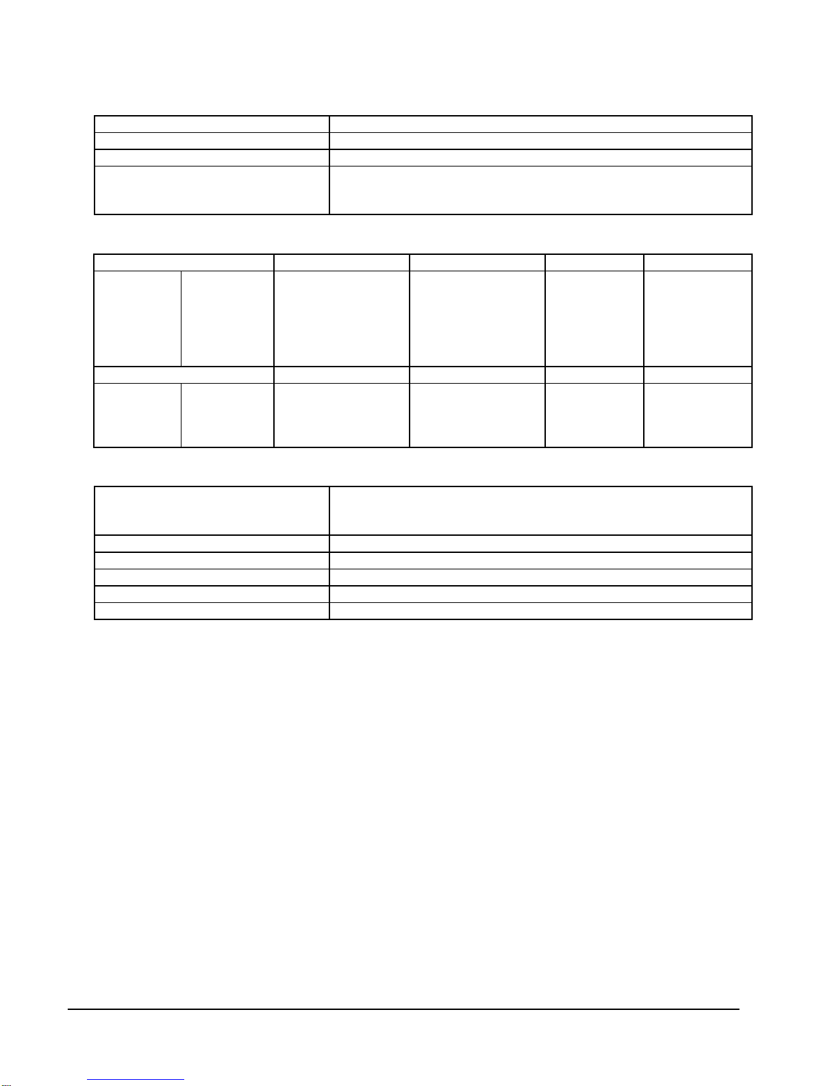
Pressing the MENU button calls up an OSD, which will be visible at the CSC-1600HD’s
scaled output. The upper text block is a Status Line and indicates which Video Input is
selected, the Output Resolution selected and Vertical Refresh Rate selected. The lower
text block has four lines, labeled Video Adjustment, Vertical Frequency Adjustment, OSD
Display and Output Terminal. Each of these has associated Sub-Menus for adjustments.
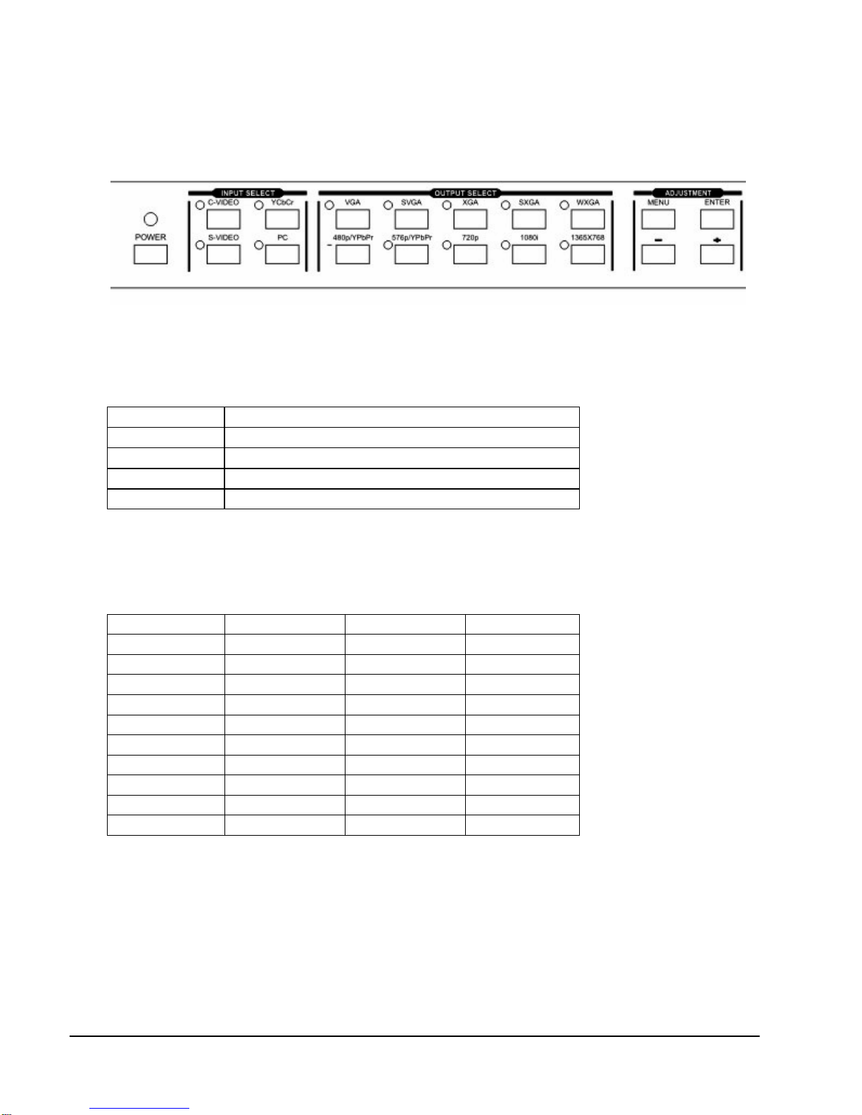
Pressing the + or – button allows you to highlight any one of these four lines and pressing
the ENTER button takes you into the Sub-Menu that allows control over the parameters
for that section. Pressing MENU while navigating always takes you back one level. After
no activity for about seven seconds, the unit automatically reverts to normal mode and the
OSD disappears.
5.2 Video Adjust Section
The CSC-1600HD has an integral Processing Amplifier, capable of adjusting various
signal parameters of the incoming video. Each one of the three input video selections (C-
V, S-V and YCbCr) has its own memory, so the settings are retained separately for each
and, when a particular input is selected, its Proc Amp settings are automatically recalled.
Note - These adjustments do not affect the incoming computer signal, which is simply
passed through the Video Scaler in the Bypass Mode.
Press MENU, then ENTER to access the following choices:
•Brightness – Sometimes called Video Level. When this is selected, press ENTER
and then + to increase the Brightness Level and – to decrease it.
•Contrast – Sometimes called Black Level. When this is selected, press ENTER and
then + to increase the Contrast Level and – to decrease it.
•Color - Sometimes called Saturation. When this is selected, press ENTER and then
+ to increase the Chroma Saturation and – to decrease it.
•Sharpness – Sometimes called Detail or Enhancement. When this is selected,
press ENTER and then + to increase the Sharpness Level and – to decrease it.
•Tint – Sometimes called Hue or Color Phase. When this is selected, press ENTER
and then + to increase the Chroma Phase in relation to the current setting and – to
decrease it. Note – This adjustment is only available for NTSC signals.
•Reset –When this is selected, press ENTER to reset all of the above parameters to
the factory preset positions.

9
5.3 Vertical Freq Adjust
Many of the Output Resolutions have multiple Vertical Refresh Rate possibilities. First
choose the desired Output Resolution by pressing the desired button in the OUTPUT
SELECT section on the front panel. Then, press MENU, choose the Vertical Freq Adjust
section and press ENTER. This Menu will display the available selections associated with
the Output Resolution selected. This may be as many as four choices, however, some
Output Resolutions have only one choice. Choose the desired rate and press ENTER.
After selection, pressing MENU twice removes the OSD from the screen.
5.4 OSD Display
Under normal conditions, the OSD will briefly display the results of changes to the Input or
Output selection. However, this feature can be turned off when it is not desirable to display
this information. For example, when the unit is being used to switch Video Inputs to a
Projector or other display during a live event and it is undesirable to have the change
displayed for all to see. To disable the OSD during these selections, press MENU,
choose the OSD Display section and press ENTER. Then you may choose OSD Display
OFF or later turn it back on. In the OFF position, the OSD only appears when the MENU
is selected and not when an Input or Output selection is made.
5.5 Output Terminal
The RGBHV or YPbPr Output Signal is available on the rear panel either on 5 BNC
connectors or an HD-15 connector, but not both simultaneously. It is necessary to choose
via the Menu which is selected. Press MENU, choose the Output Terminal section and
press ENTER. Then choose either HD-15 Output Terminal or BNC Output Terminal and
Press ENTER. Shortcuts: (1) to select the HD-15 Output Terminal, hold MENU for 3
seconds, and (2) to select the 5 BNC Output Terminal is to hold ENTER for 3 seconds.
5.6 IR Sensor
Under certain circumstances it may be desirable to disable the Infrared Sensor of the unit.
For example, if the unit is operating in the proximity of other IR-controlled devices that
may share the same commands or frequency. To disable the IR Sensor, press MENU,
choose the IR Sensor section and press ENTER. Then you may choose IR Sensor OFF
or, later turn it back on by choosing IR Sensor ON. In the OFF position, the unit will not
respond to commands from the IR Remote Control unit.
5.7 Front Panel Lockout
Under certain circumstances it may be desirable to disable the Front Panel Controls. To
do so, press MENU, choose the Front Panel Lockout section and press ENTER. Then
you may choose Front Panel Controls OFF. In the OFF position, the unit will not respond
to commands from the Front Panel. To return to normal operation, press and hold
simultaneously the + and – buttons for 3 seconds or use the IR Remote Control to gain
access to the Menu or the use the RS-232 commands.

6INFRARED REMOTE CONTROL OF THE CSC-1600HD VIDEO SCALER
The CR-16 IR Remote Unit duplicates the controls that are available via the Menu and
front panel push buttons.
7RS-232 CONTROL OF THE CSC-1600HD VIDEO SCALER
The Video Input selection and signal parameter settings for the CSC-1600HD can also be
controlled via an external control system by using the RS-232 port on the unit. If
information for this control method is required, beyond the scope of the instructions
provided in this section, please contact TV One Technical Support. A disk is provided with
the CSC-1600HD containing a sample Windows Control Panel that permits remote control
of the unit from a PC via RS-232.
Note – The connection between the CSC-1600HD unit and the RS-232 remote controller
is made with a modem cable.
Pins definition of modem cable: RS-232 transmission format:
Video Scaler Remote Controller
PIN Definition PIN Definition
1NC 1NC
2TxD 2RxD
3RxD 3TxD
4NC 4NC
5GND 5GND
6NC 6NC
7NC 7NC
8NC 8NC
9NC 9NC
BaudRate 9600bps
Data Bit 8 bits
Parity None
Stop Bit 1 bit
The IR Control unit
pictured here provides
most of the same controls
available from the front
panel of the unit.
Command/Response codes of RS-232 transmission:
The command/response code is the combination of 3 bytes. The 1st, 2nd byte are text
and the 3rd byte is value.
Remote Controller Command Codes
10

11
Code Comment
‘PW’+0
‘PW’+1 POWER power off (standby)
power on (normal)
‘IN’+0
‘IN’+1
‘IN’+2
‘IN’+3
INPUT Composite video
S-video
YCbCr
PC bypass
‘JA’+0
‘JA’+1 JACK HD-15 (D-Sub)
BNC
‘OU’+0
‘OU’+1
‘OU’+2
‘OU’+3
‘OU’+4
‘OU’+5
‘OU’+6
‘OU’+7
‘OU’+8
‘OU’+9
OUTPUT
VGA
480p
SVGA
XGA
SXGA
576p
720p
1080i
WXGA
1365x768
‘DI’+0
‘DI’+1 DISPLAY osd display OFF
osd display ON
‘BR’+value
‘CO’+value
‘SA’+value
‘SH’+value
‘TI’+value
‘RE’+0
brightness
contrast
saturation
sharpness
tint
reset
value – 0~255
value – 0~63
value – 0~127
value – 0~14
value – -30~+30
video adjustment reset
‘ZV’+value
‘ZS’+value
‘ZX’+value
vga vert freq
svga vert freq
xga vert freq
value = 0:60hz 1:72hz 2:75hz 3:85hz
value = 0:60hz 1:70hz 2:75hz
‘IR’+0
‘IR’+1 IR IR sensor OFF
IR sensor ON
‘FP’+0
‘FP’+1 PANEL front panel lockout ON
front panel lockout OFF
retrieve video scaler all status
‘AL’+0
‘PW’+? ‘IN’+? ‘JA’+?
‘OU’+? ‘DI’+? ‘IR’+?
‘FP+? ‘BR’+? ‘CO’+?
‘SA’+? ‘SH’+? ‘TI’+?
‘ZV’+? ‘ZS’+? ‘ZX’+?
Video Scaler transmits codes to Remote Controller when scaler operating.
Code Comment
‘PW’+0
‘PW’+1 POWER power off (standby)
power on (normal)
‘IN’+0
‘IN’+1
INPUT Composite video
S-video

12
‘IN’+2
‘IN’+3 YCbCr
PC bypass
‘JA’+0
‘JA’+1 JACK HD-15 (D-Sub)
BNC
‘OU’+0
‘OU’+1
‘OU’+2
‘OU’+3
‘OU’+4
‘OU’+5
‘OU’+6
‘OU’+7
‘OU’+8
‘OU’+9
OUTPUT
VGA
480p
SVGA
XGA
SXGA
576p
720p
1080i
WXGA
1365x768
‘DI’+0
‘DI’+1 DISPLAY osd display OFF
osd display ON
‘BR’+value
‘CO’+value
‘SA’+value
‘SH’+value
‘TI’+value
‘RE’+0
brightness
contrast
saturation
sharpness
tint
reset
value – 0~255
value – 0~63
value – 0~127
value – 0~14
value – -30~+30
video adjustment reset
‘ZC’+value
‘ZS’+value
‘ZX’+value
vga vert freq
svga vert freq
xga vert freq
value = 0:60hz 1:72hz 2:75hz 3:85hz
value = 0:60hz 1:70hz 2:75hz
‘IR’+0
‘IR’+1 IR IR sensor OFF
IR sensor ON
‘FP’+0
‘FP’+1 PANEL front panel lockout ON
front panel lockout OFF
‘OK’+0 video scaler power plugs in ready

13
8TROUBLESHOOTING
If the recommended actions listed below do not result in satisfactory operation, please
consult your Dealer or contact the AV Toolbox Technical Support Department directly by
Problem Possible Solution
No picture on
the output
monitor
If the Video Scaler’s Power Switch in ON, but no LED’s are illuminated,
check that the proper AC Power Cord is properly connected. If the
Power LED is illuminated, check that there is a correct Video Input
signal and that the display device connected to the output is switched
on and set to the correct input and its Brightness and Contrast are set
correctly. Check to make sure the unit has not been switched to the
correct output pin mode – HD15 or BNC.
Colors appear
wrong on the
output monitor
Try adjusting the Color, Tint, Contrast and Brightness settings on your
display. These are usually set up for viewing computer images, which
may be somewhat different from viewing images that have been up-
converted from video. Make sure your output cable assembly is not
faulty, which could prevent either the Red, Green or Blue signal from
being passed through the cable.
Too much
smearing Smearing usually occurs when a Composite Video input is used and is
generally unavoidable, unless you can switch to using S-Video. Using
good quality video cable will help towards reducing this affect.
Smearing that may not be noticeable on a small video monitor may
become objectionable on a large screen video projector.
No color on the
output monitor,
only a black and
white image
Check the condition of the cables being used. A faulty S-Video cable
can often cause a black and white image. Ensure that the color
controls on your computer monitor or video projector are all set
correctly. Ensure that the color adjustment on the Video Scaler is not
adjusted completely down. It may be necessary to reset the video
levels via the Menu functions.

14
9WARRANTY POLICY
LIMITED WARRANTY – AV Toolbox’s parent company, TV One, warrants the original
purchaser that the equipment it sells will be free from defects in materials and
workmanship for a period of two years from the date of purchase. Should this product, in
TV One's opinion, prove defective within this warranty period, TV One, at its option, will
repair or replace this product without charge. Any defective parts replaced become the
property of TV One. This warranty does not apply to those products which have been
damaged due to accident, unauthorized alterations, improper repair, modifications,
inadequate maintenance and care, or use in any manner for which the product was not
originally intended.
If repairs are necessary under this warranty policy, the original purchaser must obtain a
Return Authorization Number from TV One and return the product to a location designated
by TV One, freight prepaid. After repairs are complete, the product will be returned, freight
prepaid.
LIMITATIONS - All products sold are "as is" and the above Limited Warranty is in lieu of all
other warranties for this product, expressed or implied, and is strictly limited to two years
from the date of purchase. TV One assumes no liability to end-users for any loss of use,
revenue or profit.
TV One makes no other representation of warranty as to fitness for the purpose or
merchantability or otherwise in respect of any of the products sold. The liability of TV One
with respect to any defective products will be limited to the repair or replacement of such
products. In no event shall TV One be responsible or liable for any damage arising from
the use of such defective products whether such damages be direct, indirect,
consequential or otherwise, and whether such damages are incurred by the reseller, end-
user or any third party.
Liability Statement
Every effort has been made to ensure that this product is free of errors. TV One cannot be
held liable for the use of this hardware or any direct or indirect consequential damages
arising from its use. It is the responsibility of the user of the hardware to check that it is
suitable for his/her requirements and that it is installed correctly. All rights reserved. No
parts of this manual may be reproduced or transmitted by any form or means electronic or
mechanical, including photocopying, recording or by any information storage or retrieval
system without the written consent of the publisher.
TV One reserves the right to revise any of its hardware and software following its policy to
modify and/or improve its products where necessary or desirable. This statement does not
affect the legal rights of the user in any way.
All third party trademarks and copyrights are recognised. The AV Toolbox logo, TV One
logo, TV One-task and CORIO are the registered Trademarks of TV One. All other
trademarks are the property of their respective holders.

15
10 REGULATORY COMPLIANCE
The Video Scaler has been tested for compliance with: FCC Class A and CE
The Power Supply has been tested for compliance with: UL, CSA and CE
11 CONTACT INFORMATION
AV Toolbox Phone 859-647-1077
1350 Jamike Drive Toll Free 800-235-3280
Erlanger, KY 41018 Fax 859-282-8225
www.avtoolbox.com Email sales@avtoolbox

AV Toolbox
1350 Jamike Drive
Erlanger, KY 41018
www.avtoolbox.com
Phone 859-647-1077
Toll Free 800-235-3280
Fax 859-282-8225
Email sales@avtoolbox
Table of contents
Other AV TOOL Recording Equipment manuals