Tellabs 7300 Series User guide

Revision A, 8/09
Copyright © 2009 Tellabs. All rights reserved.
®
System Manual
76.7300FP11/2
Tellabs®7300 Metro Ethernet Switching Series
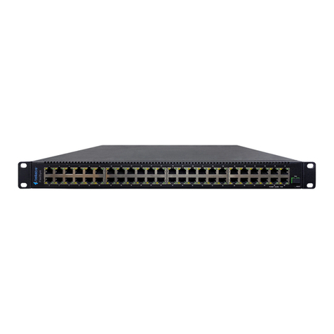
Tellabs®7345 Ethernet Aggregation Switch
Tellabs®7325 Ethernet Edge Switch

FCC Notification
Statement Federal Communications Commission (FCC) Rules require that you be notified of
the following:
This equipment has been tested and found to comply with the limits for a Class A
digital device, pursuant to part 15 of the FCC Rules. These limits are designed to
provide reasonable protection against harmful interference when the equipment is
operated in a commercial environment. This equipment generates, uses, and can
radiate radio frequency energy and, if not installed and used in accordance with the
instruction manual, may cause harmful interference to radio communications.
Operation of this equipment in a residential area is likely to cause harmful
interference in which case the user will be required to correct the interference at his
own expense.
Changes or modifications not expressly approved by Tellabs Operations, Inc., in
writing can void the user’s authority to operate the equipment.
Industry Canada
Notification Statement Industry Canada interference-causing equipment regulations require that you be
notified of the following:
This Class A digital apparatus complies with Canadian ICES-003.
Cet appareil numérique de la classe A est conforme à la norme NMB-003 du
Canada.
Copyright Statement This Tellabs manual is owned by Tellabs or its licensors and protected by U.S. and
international copyright laws, conventions, and treaties. Your right to use this manual
is subject to limitations and restrictions imposed by applicable licenses and
copyright laws. Unauthorized reproduction, modification, distribution, display or
other use of this manual may result in criminal and civil penalties.
Trademark Notice The following trademarks and service marks are owned by Tellabs Operations, Inc.,
or its affiliates in the United States and/or other countries: ACCESSMAX®,
CABLESPAN®,CEC-128®, DXX®, ®, DYNAMIC SIGNAL TRANSFER™,
EC DUO®, ENHANCED AUDIO PLUS®, EXPRESS/PATH®, FOCUS™,
INTELLIGENT SERVICE EDGE™, MARTIS®, ®, MARTISDXX®,
®, METROCARE , METROVANTAGE™, MetroWatch®,
NETREACH®, NETWISE®, SCULPTURED SOUND®, TECHNOLOGY THAT
TRANSFORMS THE WAY THE WORLD COMMUNICATES™, ®, TELLABS®,
®, TELLABS PROPARTNER™, Tellabs®ServiceAssured™Upgrade,
TELLABS. THE FUTURE OF YOUR BUSINESS. STARTING NOW™, TEL/MOR®,
THE WORLD COMMUNICATES THROUGH TELLABS™, TITAN®, VERITY®,
YOUR NETWORKING PARTNER®
Any other company or product names may be trademarks of their respective
companies.
Contact Information In an effort to improve the quality of this document, please notify Tellabs Technical
Assistance at 1.800.443.5555 in North America or 1.630.798.7070 outside North
America if any anomalous conditions are observed.
SM

System Manual Contents
76.7300FP11/2, Rev A 8/09 Page 2-i
Contents Page
Section 1 Introduction 2-1
Reason for Issue...................................................................................2-1
Conventions Used in This Manual .....................................................................2-1
Performing Numbered Steps.......................................................................2-2
Section 2 System Overview, Features, and Specifications 2-3
Tellabs 7345 Ethernet Aggregation Switch Overview........................................2-3
Tellabs 7325 Ethernet Edge Switch Overview...................................................2-3
General System Features ..................................................................................2-4
Class of Service...........................................................................................2-4
Operations, Administration and Maintenance Capabilities..........................2-4
Craft Station.................................................................................................2-4
System Administration.................................................................................2-5
Features Introduced in FP1.1.............................................................................2-5
Platform Applications .........................................................................................2-6
Specifications.....................................................................................................2-8
System Dimensions.....................................................................................2-8
Power Requirements...................................................................................2-9
Environmental Specifications.....................................................................2-10
RoHS and WEEE Compliance...................................................................2-12
Section 3 System Architecture 2-13
Switched Ethernet Services and Features.......................................................2-14
Quality of Service (QoS) ..................................................................................2-14
QoS Services ......................................................................................2-14
Overview of QoS Operations...............................................................2-15
Ethernet Service Support.................................................................................2-16
trTCM ..................................................................................................2-16
Ethernet Interface Support.........................................................................2-16
Ethernet Packet Support............................................................................2-16
System Scalability......................................................................................2-17
System Redundancy (Tellabs 7345 Switch) ....................................................2-17
Power Supplies ................................................................................... 2-17
Fans ....................................................................................................2-17
Redundancy (Tellabs 7325 Switch) .................................................................2-17
802.1D – MAC Bridging and Spanning Tree....................................................2-18
802.3 ................................................................................................................2-18
VLAN Support ..................................................................................................2-19
Traffic Management and QoS....................................................................2-20
Link Aggregation (802.3ad)..............................................................................2-20
Ethernet OAM Support.....................................................................................2-21
Maintenance Domain (MD) .................................................................2-22
Maintenance Association (MA)............................................................2-22
Maintenance Association End Point (MEP).........................................2-22
Local/Remote System Management................................................................2-23

Contents System Manual
Page 2-ii 8/09 76.7300FP11/2, Rev A
Contents Page
Section 4 System Components 2-24
Tellabs 7345 Switch System Configuration and Basic Components ...............2-24
Hardware Components..............................................................................2-25
Tellabs 7345 Shelf.....................................................................................2-27
10G Switch Module..........................................................................................2-27
Front Panel LEDs ......................................................................................2-28
10G Switch Module Physical Specifications..............................................2-29
Central Management Controller Card (CMCC) Module ...................................2-30
Front Panel LEDs ......................................................................................2-30
CMCC Physical Specifications ..................................................................2-31
Power Supply Unit (PSU).................................................................................2-32
Front Panel LEDs ......................................................................................2-32
Power Supply Unit Physical Specifications................................................2-33
Fan Tray with Filter ..........................................................................................2-33
Front Panel LEDs ......................................................................................2-34
Fan Tray Physical Specifications...............................................................2-34
Tellabs 7325 Switch Configuration and Basic Components ............................2-35
Power Supply Unit (PSU) ..........................................................................2-37
Front Panel LEDs ......................................................................................2-38
Power Supply Unit Physical Specifications................................................2-38
Small Form-Factor Pluggables (SFPs/XFPs)...................................................2-39
SFP/XFP Physical Specifications..............................................................2-39
Optional Equipment..........................................................................................2-41
7300 Extended Temp AC-DC Power Converter........................................2-41
Fuse Panel.................................................................................................2-41
Section 5 Installation 2-42
Preparation of the Installation Site ...................................................................2-42
Cooling Requirements...............................................................................2-42
Environmental Requirements ....................................................................2-43
Electrostatic Discharge (ESD) Precautions......................................................2-43
Fiber Optic Safety......................................................................................2-43
Laser Radiation Exposure .........................................................................2-43
Optical Fiber Handling ...............................................................................2-45
Unpacking the Tellabs 7300 NE Components .................................................2-46
Accessories ...............................................................................................2-46
Physical Placement..........................................................................................2-47
Installing the Tellabs 7300 Shelf ......................................................................2-48
Installing the Fuse Panel (Optional).................................................................2-48
Connecting the Fuse Panel to the BDFB...................................................2-49
Installing the Tellabs 7300 Power Converter Tray (Optional) ..........................2-51
Install the Power Converter in the Power Converter Tray .........................2-51
Install the Assembled Power Converter Tray in the Rack .........................2-54
Grounding the Tellabs 7300 Shelf....................................................................2-55
Installing the Modules (Tellabs 7345 Switch only) ...........................................2-56
Installing the Modules (Tellabs 7325 Switch only) ...........................................2-58
Connecting the DC Power Cable From the AC Power Converter Tray
(Tellabs 7325 Switch)..........................................................................2-60
Connecting the DC Power Cable From the AC Power Converter Tray
(Tellabs 7345 Switch)..........................................................................2-60

System Manual Contents
76.7300FP11/2, Rev A 8/09 Page 2-iii
Contents Page
Connecting DC Power to the Tellabs 7300 NE................................................2-62
PSU Redundancy Options (Tellabs 7345 Switch only).......................2-64
Installing the Transceivers ...............................................................................2-65
Transceiver Installation (Tellabs 7345 Switch)....................................2-65
Transceiver Installation (Tellabs 7325 Switch)....................................2-66
Connecting the Cables to the 10G Switch Module in the Tellabs 7345 Switch 2-68
RJ-45 Electrical SFP Pinouts.....................................................................2-69
Management Connections ...............................................................................2-70
Connecting Through the Ethernet Management Port (MGT1) -
Tellabs 7345 Switch......................................................................2-70
Connecting Through the Ethernet Management Port (MGT1) -
Tellabs 7325 Switch......................................................................2-71
Connecting Through the Serial RS-232 Port (CT).....................................2-72
Alarm Wiring.....................................................................................................2-73
Initializing the Tellabs 7300 NE........................................................................2-75
One Power Supply Installed................................................................2-76
Set System Time and Date Manually ........................................................2-78
Change System Time and Date..........................................................2-78
Enable Daylight Savings Time ............................................................2-78
Save Configuration..............................................................................2-79
Synchronize System Time and Date via SNTP.........................................2-79
Set Up Simple Network Time Protocol (SNTP)...................................2-79
Create New Users .....................................................................................2-80
Configure RADIUS.....................................................................................2-81
Enternal Alarm Input (Optional).................................................................2-82
Activate SNMP Traps for ENV Alarms.......................................................2-83
Deactivate SNMP Traps for ENV Alarms ..................................................2-84
External Contact Output (Optional)............................................................2-84
Wiring Contacts...................................................................................2-85
Section 6 Maintenance 2-87
Back Up the Database to Flash .......................................................................2-87
Back Up the Database to a Remote Server.....................................................2-88
Schedule a Local Backup.................................................................................2-88
Restore a Local Backup...................................................................................2-89
Restore a Remote Backup...............................................................................2-90
Upgrade the System Software.........................................................................2-90
Replace Modules .............................................................................................2-92
Module Replacement Pre-Checklist ..........................................................2-92
Replacing a CMCC Module (Tellabs 7345 Switch only)............................2-93
Replacing a PSU Module..........................................................................2-95
Replacing a 10G Switch Module (Tellabs 7345 Switch only) ....................2-98
Replacing a Fan Tray (Tellabs 7345 Switch only) ...................................2-100
Managing Fan Filter Maintenance (Tellabs 7345 Switch only)................2-101
Removing the Fan Filter....................................................................2-101
Replacing the Fan Filter....................................................................2-102
Safety Precautions.........................................................................................2-104
Optical Fiber Handling....................................................................................2-105
Fiber Optic Cleaning Requirements...............................................................2-106
Tools........................................................................................................2-108
Materials..................................................................................................2-108

Contents System Manual
Page 2-iv 8/09 76.7300FP11/2, Rev A
Contents Page
Fiber Optic Cleaning Procedures...................................................................2-109
Cleaning SC Connectors.........................................................................2-109
Cleaning LC Connectors..........................................................................2-110
Section 7 Troubleshooting 2-112
Tellabs Customer Service..............................................................................2-112
Module Replacement .....................................................................................2-112
Performance Symptoms.................................................................................2-113
Symptoms and Recommended Actions.........................................................2-113
After-Sale Technical Support ......................................................................... 2-115
Additional Information ....................................................................................2-115
Module Repair and Return.............................................................................2-116
General Repair and Return Information...................................................2-116
Contacting Tellabs Repair Centers..........................................................2-117
Appendix A Glossary 2-119

System Manual 1. Introduction
76.7300FP11/2, Rev A 8/09 Page 2-1
1. Introduction
1.01 This document provides an overview of the Tellabs®7345 Ethernet
Aggregation Switch (Tellabs 7345 Switch) and the Tellabs®7325 Ethernet Edge
Switch (Tellabs 7325 Switch) as well as specifications, installation, initialization,
maintenance, and troubleshooting information.
1.02 Tellabs 7300 Network Elements (NEs) refer to the following network
elements unless otherwise specified:
• Tellabs 7345 Ethernet Aggregation Switch
• Tellabs 7325 Ethernet Edge Switch
Reason for Issue 1.03 Tellabs issues this manual at Revision A to include the changes in Table
1.1, page 2-1.
Qualified Personnel
1.04 This document is intended for a Testing Engineer or Administrator who
may be involved in configuring the Tellabs 7345 Switch or the Tellabs 7235 Switch.
1.05 You should have a basic knowledge of Ethernet services, packet systems
and switches, and Quality of Service features supported by the hardware.
Conventions Used in This Manual
1.06 Table 1.2, page 2-1 describes the conventions and admonishments used
in this manual.
Table 1.1 Tellabs 7300 System Manual Revision History
Revision Change History Release Date
A Initial release for Tellabs 7345 Ethernet Aggregation Switch and Tellabs 7325
Ethernet Edge Switch FP1.1.x. 8/09
Table 1.2 Highlights of Syntax Conventions Used in this Manual
Convention Description
Courier Font All input commands and system responses are shown in Courier.
Note: Provides supplemental information or details.
Caution: Alerts you to the possibility of service interruption, such as a loss of traffic.
DANGER: Alerts you to the possibility of personal injury.
Warning: Alerts you to the possibility of equipment damage.

1. Introduction System Manual
Page 2-2 8/09 76.7300FP11/2,RevA
Performing Numbered Steps
1.07 Perform all numbered steps in the procedure unless specifically instructed
to skip to another step or procedure.
1.08 The numbered steps in a procedure are usually prefaced with a numbered
paragraph that describes the type of procedure that is to be performed. The
substeps ofa numbered step may require you to makea choice before proceeding.
The substeps of a numbered step reflect the number of their parent step. Refer to
Figure 1.1, page 2-2.
Figure 1.1 Example of Optional Substeps to a Numbered Step
1.10 Place a check mark on the line beside each step number in a procedure
as you complete it. Then, if a procedure must be interrupted, the place to resume
is clearly indicated. Refer to Figure 1.2, page 2-2.
Figure 1.2 Example of a Step With Checkmark Line and Response
1.09 Follow these precautions to prevent physical injury when handling optical
fiber:
__ 1. Avoid looking directly at the fiber connectors.
__ 2. If it is required to look at the connectors, perform the following actions
to prevent any hazard:
__ 2.1 Remove the optical modules or ensure the optical
modules are not powered at both the shelf near end
and shelf at the fiber path far end.
__ 2.2 Wear laser safety glasses that block all possible
wavelength ranges emitting from the equipment.
Numbered steps ask
you to perform a
function or verify a
system response.
Substeps may
indicate either a
choice as to what
step is performed
next or additional
required steps.
Numbered paragraphs
describe the type of
procedure that is to
be performed.
__ 3. Separate telecommunication cables from power cables.
After performing a step,
check it off or write down
the time of completion.

System Manual 2. System Overview, Features, and Specifications
76.7300FP11/2, Rev A 8/09 Page 2-3
2. System Overview, Features, and Specifications
2.01 The Tellabs 7345 Switch and the Tellabs 7325 Switch are an ideal fit for
aggregation offices where service providers want to dramatically and cost
effectively increase the bandwidth in their network, while the carrier class design
ensures operational efficiency for running the network reliably.
Tellabs 7345 Ethernet Aggregation Switch Overview
2.02 The Tellabs 7345 Switch is designed around a compact two rack unit
(2RU) chassis. Power is provided using redundant Power Supply Units (PSUs).
System cooling is maintained with the fan tray. External management access is
achieved with the Central Management Controller Card (CMCC) module.
2.03 The Tellabs 7345 Switch is a 44G Ethernet switch in a small 2RU shelf that
supports the latest carrier-class requirements for Ethernet networking. The Tellabs
7345 Switch is offered in a pluggable chassis with 10G Ethernet Switch modules
capable of supporting two 10GigE small form-factor pluggable (XFP) interfaces
and 24 triple-speed small form-factor pluggable (SFP)-based interfaces.
2.04 The Tellabs 7345 Switch supports Metro Ethernet Forum (MEF) based
E-line and Ethernet Local Area Network (ELAN) services for meeting the multitude
of service configurations operators require. Provider Bridging support allows
multiple Virtual Local Area Network (VLAN) tags to be applied on an Ethernet
Virtual Circuit (EVC) providing separation between the service provider VLAN
space and the customer VLAN space.
Tellabs 7325 Ethernet Edge Switch Overview
2.05 The Tellabs 7325 Switch is a 24G Ethernet switch in a one rack unit (RU)
shelf with one integrated Fan/Alarm Module, one integrated 1G Edge Switch
Module with 24 interfaces (SFPs), and two removable Power Supply Units.

2. System Overview, Features, and Specifications System Manual
Page 2-4 8/09 76.7300FP11/2,RevA
General System Features
2.06 General Tellabs 7345 Switch and Tellabs 7325 Switch features include:
•ClassofService
• Operations, Administration and Maintenance Capabilities
• Craft Station
• System Administration
Class of Service
2.07 Multiple classes of service are supported with the traffic management and
quality of service (QoS) capabilities provided by the Tellabs 7345 Switch and the
Tellabs 7325 Switch. Classification of traffic can be based on port, source or
destination Media Access Control (MAC), VLAN ID, Differentiated Service Code
Point (DSCP), or Internet Protocol (IP)-precedence. Ingress policing is provided
with a dual rate three color marking. Eight class-based queues are provided per
port providing the necessary granularity for an edge switch. Strict priority
scheduling options allow service providers to provide the appropriate fairness
algorithms for the service being provided.
Operations, Administration and Maintenance Capabilities
2.08 Carrier class Operations, Administration and Maintenance (OAM)
capabilities are provided by supporting the latest industry OAM standards. The
Tellabs 7345 Switch and the Tellabs 7325 Switch support 802.3ah link-layer OAM
and 802.1ag Ethernet connectivity fault management. These capabilities allow
service providers to receive rapid notification of network faults while providing a
mechanism to ensure service level agreements are being met.
Craft Station
2.09 The Tellabs 7191 Craft Station supports local craft activities such as
network element turn up and fault repair. The craft station can be installed on a
laptop and can be used as an autonomous and portable management system.
2.10 Multiple management options are supported allowing the system to be
deployed in many locations. For deployments with direct access to a management
network, the Tellabs 7345 Switch and the Tellabs 7325 Switch can be directly
connected to the network using the MGT port interface on the CMCC module in the
Tellabs 7345 Switch and on the integrated 1G Edge Switch Module in the Tellabs
7325Switch.For deployments with nodirect accessto a managementnetwork, the
Tellabs 7345 Switch and the Tellabs 7325 Switch support being managed over an
in-band management VLAN channel. For local craft access, a serial craft terminal
interface port is also provided.
2.11 Referto the Tellabs7191 Craft Station SoftwareRelease DocumentforNE
and craft station Feature Package compatibility.

System Manual 2. System Overview, Features, and Specifications
76.7300FP11/2, Rev A 8/09 Page 2-5
System Administration
2.12 System administration is performed using Command Line Interface (CLI)
and Simple Network Management Protocol (SNMP). All system provisioning
operations may be performed using either the CLI interface or using SNMP
Management Information Bases (MIBs). SNMP traps are used to provide
autonomous notifications of system problems (alarms and events). Any standard
trap manager may be used to monitor the system.
Features Introduced in FP1.1
2.13 The following new features are supported in FP1.1:
• Retrieve transmitted (PST) and received (PSR) optical power for an
SFP/XFP
• Retrieve transceiver temperature, internally measure supply voltage,
and transmit bias current for an optical SFP/XFP
• RADIUS protocol - The RADIUS protocol carries authentication,
authorization, and configuration information between a Tellabs 7300
NE (client) and the RADIUS server. It provides the ability to manage a
single database of users that contain user names, passwords, and
configuration information that can be used across many systems.
• Far End Fault Indication (FEFI)
• Configuration of Telemetry Parameters
• 32K MAC Table
• MAC Port Management
- Enable/disable VLAN ID translation
- Add, remove, modify VLAN ID mapping
• Static and Dynamic MAC Forwarding
• LAG Management
- Enable/disable VLAN ID translation
- Add, remove, modify VLAN ID mapping
- VLAN priority mapping
• Traffic Class Mapping
- Configuration of class of service, VLAN priority, and DEI
• Traffic Policer
- New color aware mode and meter type
• Scheduling
- SP + DWRR scheduling

2. System Overview, Features, and Specifications System Manual
Page 2-6 8/09 76.7300FP11/2,RevA
• Shaping
-Port
- Class of service
• Performance Management
- VLAN statistics - frames transmitted/received per VLAN
• AIS Management under MEP
• VLAN Mirroring
2.14 The Tellabs 7345 Switch supports the following new hardware
components in FP1.1:
• 82 version of 731150A/B/C 10G Switch modules (You must use the 82
issue 731150s, the 81 issue modules are not supported in FP1.1. The
82 issue 731150s support advanced functionality beginning in FP1.1
compared to the 81 issue modules.)
2.15 The Tellabs7325 Ethernet EdgeSwitch is supported in FP1.1.TheTellabs
7325 Switch is an Ethernet switch that supports 1GE interfaces. The system
contains the following hardware components:
• One integrated 1G Edge Switch module which supports up to 24
triple-speed SFP-based interfaces.
• Integrated fan.
• Two removable power supply units.
Platform Applications
2.16 The Tellabs 7345 Switch is a key component of Tellabs’ Carrier Ethernet
portfolio designed to provide end-to-end Ethernet services. The Tellabs 7345
Switch is typically used in aggregation and customer premise locations. As an
aggregation device, the Tellabs 7345 Switch collects traffic from smaller Ethernet
switches (for example, Tellab 7325 Switch) and demarcation devices (for example,
Tellabs 7305 Ethernet Demarcation Device) and combines the traffic into highly
filled 10 GbE links that plug into large layer 2 or layer 3 networks. Other elements
of the Tellabs Carrier Ethernet solution are used to create these larger networks.
As a customer premise device, the Tellabs 7345 Switch is used at customer
locations that require uplinks as high as 10G or locations that require a higher
degree of resiliency than may be found in traditional non-redundant Ethernet
switch solutions.
2.17 Figure 2.1, page 2-7 depicts Tellabs’ Carrier Ethernet solution providing
end-to-end services. The Tellabs 8800 is a multipurpose router used to build core
IP/MPLS networks. The Tellabs 7100 is a Packet Optical Transport System that
combines ROADM based optical networking with high capacity Ethernet switching
for building large metro Ethernet networks. The Tellabs 7325 Switch is an Ethernet
Edge Switch that supports Ethernet aggregation and customer premise
applications for demands requiring multiple gigabit Ethernet or fast Ethernet
interfaces. The Tellabs 7305 is a 1G Ethernet Demarcation Device that provides
advanced Network Interface Device (NID) functionality for Ethernet service
handoffs.

System Manual 2. System Overview, Features, and Specifications
76.7300FP11/2, Rev A 8/09 Page 2-7
Figure 2.1 Customer Premise Application
2.18 Tellabs’CarrierEthernet solutionprovidesthe necessary elementsto build
a wide array of Carrier Ethernet services. Whether building a network to support
business services, residential high speed data, or mobile wireless backhaul, the
Tellabs’ Carrier Ethernet solutions are an excellent choice. A wide range of
platform sizesareavailableto meet themany cost pointsthat arerequiredforthese
networks. Sophisticated traffic management and QoS capabilities are available
across the solution to provide differentiated services. Extensive OAM support is
also available to support proactive network monitoring and stringent service level
agreements (SLAs).
2.19 The Tellabs Carrier Ethernet solution and the Tellabs 7345 Switch are
integral components for supporting the latest Carrier Ethernet features.

2. System Overview, Features, and Specifications System Manual
Page 2-8 8/09 76.7300FP11/2,RevA
Specifications
2.20 Refer to the following subsections for system requirements, system
dimensions, and environmental specifications of the Tellabs 7345 Switch and the
Tellabs 7325 Switch.
System Dimensions
2.21 Refer to Table 2.1, page 2-8 for physical characteristics of the Tellabs
7345 shelf and to Table 2.2, page 2-8 for physical characteristics of the Tellabs
7325 Switch.
Table 2.1 Tellabs 7345 Shelf Dimensions
Characteristic Value
Height 3.48 inches (88.5 mm)
Width 18.9 inches (480 mm)
Base Depth 11.0 inches (279.4 mm)
Weight 8.42 pounds (3.82 Kg) chassis only
14.31 pounds (6.49 Kg) chassis with full complement of modules (two
10G Switch Modules, two Power Supply Unit modules, one CMCC
Module, one Fan Tray, and one CMCC front panel)
Table 2.2 Tellabs 7325 Switch Dimensions
Characteristic Value
Height 1.75 inches (44.45 mm)
Width 17.5 inches (444.5 mm)
Depth 11.0 inches (279.4 mm)
Weight 7.8 pounds (3.6 Kg)

System Manual 2. System Overview, Features, and Specifications
76.7300FP11/2, Rev A 8/09 Page 2-9
Power Requirements
2.22 The Tellabs 7345 Switch operates on -48 Vdc nominal. Refer to Table 2.3,
page 2-9 for power information.
2.23 The Tellabs 7325 Switch operates on -48 Vdc nominal. Refer to Table 2.4,
page 2-9 for power information.
Table 2.3 Tellabs 7345 Switch Power Requirements
Tellabs 7345 Switch Primary Component Values Maximum Power BTUs
81.07300A-R517300 Shelf 250 Watts2853
81.73040-R5 7300 Fan Tray with Filter 30 Watts 102
81.CM3501-R5 7300 Power Supply 20 Watts 68
81.CM3502-R5 7300 CMCC (Central Management Controller
Card) 10 Watts 34
82.731150A-R5 7345 Ethernet Aggregation Switch - 10G
(2 XFP, 24 SFP) 85 Watts 290
82.731150B-R5 7345 Ethernet Aggregation Switch - 10G
(1 XFP, 24 SFP) 80 Watts 273
82.731150C-R5 7345 Ethernet Aggregation Switch - 10G
(0 XFP, 24 SFP) 75 Watts 256
1. Assumes the following equipment installed: two 10G Switch modules, two PSU modules, one CMCC module, and one Fan Tray
with filter.
2. Tellabs recommends that -48 Vdc be fused at 7.5 Amps.
Table 2.4 Tellabs 7325 Switch Power Requirements
Tellabs 7325 Switch Primary Component Values Maximum Power BTUs
81.7325A-R517325 Switch 85 Watts2290
1. Assumes the following equipment installed: one integrated 1G Edge Switch module, one integrated fan module, and two PSU
modules.
2. Tellabs recommends that -48 Vdc be fused at 3 Amps.

2. System Overview, Features, and Specifications System Manual
Page 2-10 8/09 76.7300FP11/2,RevA
Environmental Specifications
2.24 The Tellabs 7345 Switch and the Tellabs 7325 Switch are designed to
meet both NEBS and ETSI standards for the following environmental
specifications:
• Environmental Operational Ranges, Table 2.5, page 2-10
• Electromagnetic Compatibility (EMC), Table 2.6, page 2-12
• Health And Safety, Table 2.7, page 2-12
2.25 The Telcordia references in this section apply to the issues of Telcordia
GR-63-CORE, “NEBS Requirements: Physical Protection,” and Telcordia
GR-1089-CORE, “Electromagnetic Compatibility and Electrical Safety,” available
at the date of product release.
Table 2.5 Environmental Operational Ranges
Description Specification NEBS Standard ETSI Standard
Central Spatial Requirements Meets criterion of the
listed standard GR-63-CORE, 2 ETSI TR 102 489
ThermalManagement
Guidance for
Equipment and its
deployment
Operating Temperature 23°F to +104°F
(-5°C to +40°C) GR-63-CORE, 4.1.2 ETSI EN 300 019-2-3
T 3.2 Environmental
test specifications:
Stationary use at
weatherproofed
locations.
Temperature-
controlled locations.
Operating Thermal, Short
Term1 23°F to 122°F
(-5°C to 50°C)
Short-term = 96 hours
maximum
Maximum Rate of Temperature
Change 86°F (30°C) per hour
(0.5°C) per minute GR-63-CORE, 4.1.2 ETSI EN 300 019-2-3
T 3.2 Environmental
test specifications:
Stationary use at
weatherproofed
locations.
Temperature-
controlled locations.
Operational Humidity 5 percent to 85 percent GR-63-CORE, 4.1.2 ETSI EN 300 019-2-3
T 3.2 Environmental
test specifications:
Stationary use at
weatherproofed
locations.
Temperature-
controlled locations.

System Manual 2. System Overview, Features, and Specifications
76.7300FP11/2, Rev A 8/09 Page 2-11
Operational Humidity, Short
Term15 percent to 93 percent,
but not to exceed 0.024 kg
water/kg of dry air
GR-63-CORE, 4.1.2 ETSI EN 300 019-2-3
T 3.2 Environmental
test specifications:
Stationary use at
weatherproofed
locations.
Temperature-
controlled locations.
Altitude (NEBS) From 197 feet
(60 meters) below mean
sea level up to 13,000 feet
(4000 meters) above
mean sea level2
GR-63-CORE, 4.1.3 ETSI EN 300 019-2-3
T 3.1 Environmental
test specifications:
Temperature-
controlled locations.
Transportation and Storage
Environments Meets performance
criteria of NA and
European Standard
shown
GR-63-CORE, 4.1 ETSI ETS 300
019-2-1 T 1.2
Specification of
Environmental test:
Storage.
ETSI ETS 300
019-2-2 T 2.3
Specification of
Environmental test:
Transportation.
Thermal Heat Dissipation Meets performance
criteria of NA Standard
shown
GR-63-CORE, 4.1.6 Not specified by ETSI
Office Vibrations; Earthquake
Vibrations Zone 4
Transportation Vibration
Meets performance
criteria of NA and
European Standard
shown
GR-63-CORE, 4.4 ETSI EN 300 019-2-3
T 3.1 Environmental
test specifications:
Temperature-
controlled locations.
ETSI ETS 300
019-1-3 A1
Earthquake
conditions.
Airborne Contaminants (indoor
levels) Meets performance
criteria of NA Standard
shown
GR-63-CORE, 4.5 Not specified by ETSI
Acoustic Noise (NEBS) maximum of
78 dBA (sound pressure)
(ETSI) maximum of
72 dBA (sound power)
GR-63-CORE, 4.6 ETSI ETS 300 753
Environmental test
specifications:
Telecommunication
equipment room,
attended.
Table 2.5 Environmental Operational Ranges (Continued)
Description Specification NEBS Standard ETSI Standard

2. System Overview, Features, and Specifications System Manual
Page 2-12 8/09 76.7300FP11/2,RevA
RoHS and WEEE Compliance
2.26 The components of the Tellabs 7345 Switch and the Tellabs 7325 Switch
meet the following directives:
• Waste from Electrical and Electronic Equipment (Directive
2002/96/EC)
• Restriction of Hazardous Substances 5/6 (Directive 2002/95/EC)
Illumination Meets performance
criteria of NA standard
shown
GR-63-CORE, 4.7 Not specified by ETSI
1. Short-term refers to a period of not more than 96 consecutive hours and a total of not more than 15 days in 1 year. (This refers to
a total of 360 hours in any given year, but no more than 15 occurrences during that 1-year period.)
2. Maximum ambient temperature will degrade to 131°F (55°C) if the altitude range is 6000 feet (1800 meters) to 13,000 feet (4000
meters).
Table 2.5 Environmental Operational Ranges (Continued)
Description Specification NEBS Standard ETSI Standard
Table 2.6 Electromagnetic Compatibility (EMC)
Description North American Standard European Standard
ESD Immunity GR-1089-CORE, 2.2 EN 300 386-2 European EMC
EMI Emissions GR-1089-CORE, 3.2
EMI Immunity GR-1089-CORE, 3.3
Table 2.7 Health and Safety
Description North American Standard European Standard
Listing Requirements, Intra-Building
Lightning Surge GR-1089-CORE, 4
IEC 60950, European Safety
System Fire Test GR-63-CORE, 4.2
Electrical Safety GR-1089-CORE, 7
Bonding and Grounding GR-1089-CORE, 9
Laser Safety 21 CFR 1040 US FDA CDRH or
GR-468 EN60825-1 Safety of Laser
Products Part 1: Equipment
Classification, Requirements and
users Guide Safety
IEC 60825-2 Safety of Laser
Products Part 2: Safety of Optical
Fiber Communication Systems
UL Listing and CE Marking UL 60950 CSA C22.2 and EN
300386 V1.3.3 IEC 60950, European Safety

System Manual 3. System Architecture
76.7300FP11/2, Rev A 8/09 Page 2-13
3. System Architecture
3.01 This section covers the overall architecture of the Tellabs 7300 NEs,
including the following topics:
3.02 Features and capabilities include the following:
• Carrier-class platform
- Temperature hardened
- Redundant power supplies
- NEBS 3 certified
• Ethernet services
- 802.3—Ethernet
- 802.3ad—Link Aggregation
- 802.1D—MAC Bridging
- STP/RSTP
- 802.1Q—VLAN switching/stacking
- MSTP
- 802.1ad—Provider Bridging
- Single/Dual Rate Policer
- Rate-limiting/prioritization
• Ethernet OAM
- 802.3ah—Link OAM
- 802.1ag—Ethernet Connectivity and Fault Management
• Integrated Management
- In-band management VLAN
- SNMP and CLI
• Ethernet interfaces
- 24 - 10/100/1000 Base-T, 1GbE, and 100BaseFX SFPs
- 2 - 10GigE XFPs (Tellabs 7345 Switch only)

3. System Architecture System Manual
Page 2-14 8/09 76.7300FP11/2,RevA
Switched Ethernet Services and Features
3.03 Service providers are enhancing their Ethernet networks to address the
combination of residential triple play services and business services in a single
network. Traditional Ethernet bridging is based on sending traffic to all ports
connected to a switch. This works in a LAN environment, but as the number of
ports increases, the traffic expands to a point where the network is overwhelmed.
3.04 With the need to deliver residential triple play services and business
services over a converged network, the ability to guarantee bandwidth and
end-to-end service performance becomes a necessity. Traditional enterprise
Ethernet and pure-IP options do not provide these bandwidth and end-to-end
service performance guarantees.
3.05 Guaranteesallowserviceproviderstoestablish differentclassesofservice
level agreements for multiple types of traffic from multiple types of customers. This
can include residential or business customers with best effort or guaranteed
low-latency/high availability traffic for Internet access, video, or voice traffic.
3.06 The tools for enabling these agreements include aggregate flow control
level policing at the ingress of a network, shaping at the egress of a network, and
priority queuing throughout the network.
3.07 Extensions have been created to increase the scalability of Ethernet
networks by allowing partitioning of the network. The first extension was the virtual
LAN (VLAN) with an identifying tag. Traffic arriving at a port on a switch with a
particular VLAN is flooded only to the other ports in the switch associated with this
tag. Since the tag field was 12-bits, up to 4096 VLANs could be supported in a
network. A second extension has been added to increase the VLAN space by
separating operator VLANs from customer VLANs. The Provider Bridging
standard, 802.1ad, defines using multiple VLAN tags per frame within a network to
provide this separation and increase the VLAN space to 4096 by 4096.
Quality of Service (QoS)
3.08 The QoS service policy directs the switch on the method to handle packets
that are received by the interface. The service policy is associated with each
Ethernet interface.
QoS Services 3.09 The QoS features available on the switch provides the following services:
• Congestion management
• Traffic marking
• Traffic shaping and policing
• Traffic scheduling
• Ability to handle differential services and queuing requirements
This manual suits for next models
2
Table of contents
Other Tellabs Switch manuals
Popular Switch manuals by other brands
Orro
Orro Multiway installation guide
Dell
Dell PowerConnect B-FCX624 Hardware installation guide
SMC Corporation
SMC Corporation D-M9N-588 Series Installation and maintenance manual
SMC Networks
SMC Networks SMC6709GL2 Technical specifications
Extron electronics
Extron electronics MPS 601 user guide
LevelOne
LevelOne GEU-2429 Quick installation guide
