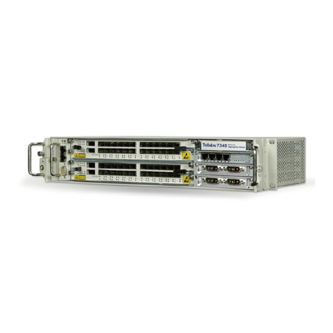
Tellabs 6325 Assembly instructions

Copyright © 2006 Tellabs. All rights reserved.
Technical Documentation
Product family Tellabs®6300 Managed
Transport System
Product name Tellabs®6325 Edge Node
Document Hardware Installation Manual
MA365 / Revision A2

2MA365 • Rev. A2
Tellabs®6325 Edge Node Legal Notices
Legal Notices
Copyright Statement This Tellabs manual is owned by Tellabs or its licensors and protected by U.S.
and international copyright laws, conventions, and treaties. Your right to use
this manual is subject to limitations and restrictions imposed by applicable li-
censes and copyright laws. Unauthorized reproduction, modification, distri-
bution, display or other use of this manual may result in criminal and civil
penalties.
Trademark Notice The following trademarks and service marks are owned by Tellabs Opera-
tions, Inc., or its affiliates in the United States and/or other countries: AUDIO
PLUS®, CABLESPAN®, CEC-128™, DYNAMIC SIGNAL TRANSFER™,
DXX®, DXX logo®, EC DUO®, ENHANCED AUDIO PLUS®, EX-
PRESS/PATH®, FOCUS™, MARTIS®, MARTISDXX®, MARTIS logo®, MAR-
TISDXX logo®, METROVANTAGE®, METROWATCH™, NETREACH®,
NETWISE®, SCULPTURED SOUND™, TELLABS®, TELLABS and T sym-
bol®, T symbol, TELLABS PROPARTNER™, TEL/MAP™, TEL/MOR®, THE
WORLD COMMUNICATES THROUGH TELLABS™, TITAN®, VERITY™,
YOUR NETWORKING PARTNER®.
Any other company or product names may be trademarks of their respective
companies.

MA365 • Rev. A2 3
Tellabs®6325 Edge Node Environmental Notices
Environmental Notices
Instructions for use,
maintenance and
management of residual
product
The equipment covered in this manual has been designed to fulfil the environ-
mental demands of market and society. There are no apparent hazards during
use and on-site maintenance of the equipment. We recommend that repair of
defective equipment takes place at Tellabs premises, and it is likewise recom-
mended to dispose of the equipment by use of certified local waste contractors
that can assure environmental safe handling and disposal of the equipment.
Arrangement for disposal of equipment can also be made through Tellabs.
Waste handling in
member states of the
European Union
The equipment covered in this manual must be disposed of in accordance
with "Directive 2002/96/EC of the European Parliament and of the council of
27 January 2003 on waste electrical and electronic equipment (WEEE)".
Disposal must follow national legislation for "IT and telecommunications
equipment" in accordance with the WEEE directive.
• Do not dispose of waste electrical and electronic equipment with unsorted
municipal and household waste
• Collect the equipment separately
• Return the equipment through the collection system agreed with Tellabs.
Correct handling of the disposed equipment contributes to reuse, recycling
and other form of recovery to protect the environment.
Label The equipment is marked with the figure shown below, to indicate that the
equipment must be collected separately. In case of very small products, the
figure may only be on the packaging or in this manual. The Tellabs name and
the production date will also be labelled on the product.
Further information For further information about separation and handling the disposed equip-
ment to ensure correct reuse or recycling, please look at www.tellabs.com.

4MA365 • Rev. A2
Tellabs®6325 Edge Node Revision Information
Revision Information
Revision history This manual has changed as follows:
Rev. Date Description of Changes
A1 Feb. 22, 2006 First version of the manual.
A2 June 14, 2006 Compared to revision A1:
• Minor changes have been performed.

MA365 • Rev. A2 5
Tellabs®6325 Edge Node Warnings and Precautions
Warnings and Precautions
Overview It is important that you read these safety information before you begin to in-
stall or performing service on the equipment. Chose one of the following:
•‘Warnings and Precautions’ on page 5 (this section)
•‘Sicherheit Informationen’ on page 7
Laser radiation Be aware of the warnings described here when installing and performing ser-
vice on the equipment. The following rules describe how to avoid hazardous
situations.
Warning Please note the following warning.

6MA365 • Rev. A2
Tellabs®6325 Edge Node Warnings and Precautions
ESD precaution Use an antistatic bracelet connected to the subrack while installing or servic-
ing the system. Do this to avoid damaging components sensitive to static elec-
tricity. Connect the antistatic bracelet to the subrack as shown in the figure be-
low.

MA365 • Rev. A2 7
Tellabs®6325 Edge Node Sicherheit Informationen
Sicherheit Informationen
Überblick Die folgenden Sicherheit Informationen bitte berücksichtigen:
•‘Warnungen und Vorkehrungen’ on page 7
•‘Spezifikationen’ on page 10
Warnungen und Vorkehrungen
Laserstrahlung Berücksichtigen Sie die Warnungen, die hier beschrieben werden, wenn Sie
Installierung oder Wartung an der Ausrüstung durchführen. Bitte halten Sie
folgende Regeln ein um gefährliche Situationen zu vermeiden.
Warnung Die folgende Warnung bitte merken.

8MA365 • Rev. A2
Tellabs®6325 Edge Node Sicherheit Informationen
Vorkehrungen über
elektrostatische
Entladung
Benutzen Sie einen antistatischen Armband auf dem Handgelenk, der an das
Baugruppenträger beim Installierung oder Wartung des Systems angeschlos-
sen wird. Tun Sie dies, um zerstörende Einzelteile zu vermeiden, die für
statisch Elektrizität empfindlich sind. Schließen Sie den antistatischen Arm-
band an das Baugruppenträger an wie in der Abbildung gezeigt.
Warnung wenn Sie
Baugruppenträger in ein
Gestell anbringen
Das Baugruppenträger muß auf unbemalten Gestell Bereich angebracht wer-
den. Auf Seite 24 bitte sehen, wie man das Baugruppenträger anbringt.
(‘To install the subrack for the Tellabs 6325 node’ on page 24).
Warnung wenn Sie PS-
DC Einschübe anbringen
Sicherstellen, die PS-DC Einschübe mit den Schrauben zu befestigen, wie im
folgenden Verfahren beschrieben, wenn Sie PS-DC Einschübe in das Baugrup-
penträger anbringen. Sehen Sie auf Seite 25 (‘To install the support modules’
on page 25).

MA365 • Rev. A2 9
Tellabs®6325 Edge Node Sicherheit Informationen
Externe Erdleitung zum
Tellabs 6325 node
Es ist lebenswichtig, daß das Tellabs 6325 node richtig geerdet wird. Wenn es
in ein Gestell angebracht wird, wird das Tellabs 6325 node an das Gestell Be-
zugspotential durch die Haltewinkel (Masse, Erdungspotential) und der Er-
dung Stift (Stift 2) des Spg.Versorgungsteilsteckers gebunden.
Die externe Erdung an
das Tellabs 6325 node
anschließen
Wenn das Tellabs 6325 node nicht in ein Gestell angebracht wird, muß das
Baugruppenträger an ein erdenpotential durch den Erdung Stift (Stift 2) ge-
bunden werden vom Spg.Versorgungsteilstecker oder indem man einen ex-
ternen Erdungsdraht bis eine der Baugruppenträger Schrauben anschließt.
Den Erdungsdraht wie in der Abbildung gezeigt anschließen. Ein gelbes/
grünes flexiblen Erdungsdraht, Minimum AWG#18 (0.75 mm2) benutzen, das
Erdungsdraht mit einem verzinnten Ringzunge Anschluß passen (zwecks Ko-
rrosion vermeiden und einen niedrigen Widerstandanschluß erreichen) und
die Schraube M4x8 und die Unterlegscheibe benutzen (geliefert mit dem
Baugruppenträger) um die Leitung anzubringen.
Anschließen der
Gleichstrom (DC)
Die folgenden Anmerkungen bitte beobachten, wenn Sie die Gleichstrom an
das Tellabs 6325 node anschließt.
• Bevor Sie die Kabel anschließt, das Spg.Versorgungsteil trennen, indem
Sie ausschalten oder die Sicherungen vom Spannungsverteilerbrett (PDP)
entfernen.
• Wenn Sie das Spg.Versorgungsteilkabel zwischen das PS-DC Einschub
und das PDP anbringst, sicherstellen, den Erdungsdraht des Spg.Versor-
gungsteilkabels an die Erdleitung des PDP anzuschließen.
• Wenn Sie das Anschließen des Spg.Versorgungsteilkabels durchgeführt
hast, wie im Verfahren auf Seite 35 beschrieben (‘To connect the DC pow-
er’ on page 35), das Spg.Versorgungsteil dann anschließen, indem Sie ein-
schalten oder die Sicherungen auf dem PDP wieder einfügen.

10 MA365 • Rev. A2
Tellabs®6325 Edge Node Sicherheit Informationen
Warnung wenn Sie
Wechselstrom (AC)
benutzen
Sicherstellen, das Tellabs 6325 node an Sicherheit Masse anzuschließen, wenn
Sie Wechselstrom und dadurch den externen AC/DC Zusatzgerät benutzt.
Ein externer Erdungsdraht muß an das Baugruppenträger angeschlossen wer-
den. Den Erdungsdraht wie in der Abbildung gezeigt anschließen. Ein
gelbes/grünes flexiblen Erdungsdraht, Minimum AWG#18 (0.75 mm2) be-
nutzen, das Erdungsdraht mit einem verzinnten Ringzunge Anschluß passen
(zwecks Korrosion vermeiden und einen niedrigen Widerstandanschluß erre-
ichen) und die Schraube M4x8 und die Unterlegscheibe benutzen (geliefert
mit dem Baugruppenträger) um die Leitung anzubringen.
Spezifikationen
Plazierung Richtlinien Das Tellabs 6325 node ist entworfen, um in einem typischen kommerziellen
Klima zu funktionieren. Die folgenden Richtlinien bitte beobachten:
• Im Falle des Wechselstroms einen geerdeten, dreizackigen Energie An-
schluß benutzen, der durch den elektrischen Code der Region genehmigt
wird.
• Platz muß sauber, staubfrei und gut gelüftet sein.
• Entlüftungsbohrungen nicht zudecken.
Anforderungen an
Sicherheit
Die Anforderungen von EN 60950-1 "Sicherheit der Informationstechnolo-
gieausrüstung" wird erfüllt. Der beabsichtigte Gebrauch des Tellabs 6325
node ist auf Plätzen mit eingeschränktem Zugang, wie in EN 60950-1 defini-
ert.
Die Anforderungen von EN 60825-1: Ausrüstung Klassifikation, Anforderun-
gen und Benutzers Handbuch und EN 60825-2: Sicherheit der optischen Ko-
mmunikationssysteme, werden erfüllt.
Eine automatische Laser Abschaltung Funktion wird für die optischen
Schnittstellen STM-1/4/16 zur Verfügung gestellt. Diese Funktion stimmt mit
ITU-T G.664 überein: Optische Sicherheit Verfahren und Anforderungen für
optische Transportsysteme.

Tellabs®6325 Edge Node Contents
MA365 • Rev. A2 11
Legal Notices . . . . . . . . . . . . . . . . . . . . . . . . . . . . . . . . . . . . . . . . . . . . . 2
Environmental Notices . . . . . . . . . . . . . . . . . . . . . . . . . . . . . . . . . . . . . . 3
Revision Information . . . . . . . . . . . . . . . . . . . . . . . . . . . . . . . . . . . . . . . . 4
Warnings and Precautions . . . . . . . . . . . . . . . . . . . . . . . . . . . . . . . . . 5
Sicherheit Informationen . . . . . . . . . . . . . . . . . . . . . . . . . . . . . . . . . . 7
Warnungen und Vorkehrungen . . . . . . . . . . . . . . . . . . . . . . . . . . . . . . . 7
Spezifikationen . . . . . . . . . . . . . . . . . . . . . . . . . . . . . . . . . . . . . . . . . . . 10
Preface . . . . . . . . . . . . . . . . . . . . . . . . . . . . . . . . . . . . . . . . . . . . . . . . 13
Purpose of the Manual . . . . . . . . . . . . . . . . . . . . . . . . . . . . . . . . . . . . . 13
Structure of the Manual . . . . . . . . . . . . . . . . . . . . . . . . . . . . . . . . . . . . 13
Abbreviations . . . . . . . . . . . . . . . . . . . . . . . . . . . . . . . . . . . . . . . . . . . . 13
Definition of Terms . . . . . . . . . . . . . . . . . . . . . . . . . . . . . . . . . . . . . . . . 14
References . . . . . . . . . . . . . . . . . . . . . . . . . . . . . . . . . . . . . . . . . . . . . . 15
1 Overview . . . . . . . . . . . . . . . . . . . . . . . . . . . . . . . . . . . . . . . . . . . . . . 19
2 Installation Information . . . . . . . . . . . . . . . . . . . . . . . . . . . . . . . . . . 21
2.1 Optical Safety Considerations . . . . . . . . . . . . . . . . . . . . . . . . . . . . . . . 21
2.2 Labels on Equipment . . . . . . . . . . . . . . . . . . . . . . . . . . . . . . . . . . . . . . 22
2.3 Physical Placement . . . . . . . . . . . . . . . . . . . . . . . . . . . . . . . . . . . . . . . 23
2.4 Installing the Subrack . . . . . . . . . . . . . . . . . . . . . . . . . . . . . . . . . . . . . . 24
2.5 Installing the Modules . . . . . . . . . . . . . . . . . . . . . . . . . . . . . . . . . . . . . . 25
2.6 Installing the Transceivers . . . . . . . . . . . . . . . . . . . . . . . . . . . . . . . . . . 27
2.7 Connecting the Cables . . . . . . . . . . . . . . . . . . . . . . . . . . . . . . . . . . . . . 28
2.8 Removing a Module from the Subrack . . . . . . . . . . . . . . . . . . . . . . . . . 37
3 Reference Information . . . . . . . . . . . . . . . . . . . . . . . . . . . . . . . . . . . 39
3.1 Front Layout . . . . . . . . . . . . . . . . . . . . . . . . . . . . . . . . . . . . . . . . . . . . . 39
3.2 Logistics . . . . . . . . . . . . . . . . . . . . . . . . . . . . . . . . . . . . . . . . . . . . . . . . 41
3.3 LEDs, Switch and Connectors . . . . . . . . . . . . . . . . . . . . . . . . . . . . . . . 45
3.4 Functional Description . . . . . . . . . . . . . . . . . . . . . . . . . . . . . . . . . . . . . 48
3.5 Specifications . . . . . . . . . . . . . . . . . . . . . . . . . . . . . . . . . . . . . . . . . . . . 51
3.5.1 SDH Optical Interfaces . . . . . . . . . . . . . . . . . . . . . . . . . . . . . . 51
3.5.2 PDH Electrical Interfaces . . . . . . . . . . . . . . . . . . . . . . . . . . . . 55
3.5.3 Synchronization Interface . . . . . . . . . . . . . . . . . . . . . . . . . . . . 56
3.5.4 Management Interfaces . . . . . . . . . . . . . . . . . . . . . . . . . . . . . 59
3.5.5 Power . . . . . . . . . . . . . . . . . . . . . . . . . . . . . . . . . . . . . . . . . . . 60
3.5.6 Mechanical . . . . . . . . . . . . . . . . . . . . . . . . . . . . . . . . . . . . . . . 61
3.5.7 Environmental . . . . . . . . . . . . . . . . . . . . . . . . . . . . . . . . . . . . . 68
3.5.8 EMC Conditions . . . . . . . . . . . . . . . . . . . . . . . . . . . . . . . . . . . 70
3.5.9 Safety . . . . . . . . . . . . . . . . . . . . . . . . . . . . . . . . . . . . . . . . . . . 73
3.5.10 R&TTE . . . . . . . . . . . . . . . . . . . . . . . . . . . . . . . . . . . . . . . . . . 73
3.5.11 MTBF . . . . . . . . . . . . . . . . . . . . . . . . . . . . . . . . . . . . . . . . . . . 74
A Packing Instructions . . . . . . . . . . . . . . . . . . . . . . . . . . . . . . . . . . . . . 75
Index . . . . . . . . . . . . . . . . . . . . . . . . . . . . . . . . . . . . . . . . . . . . . . . . 79

Tellabs®6325 Edge Node Contents
12 MA365 • Rev. A2

MA365 • Rev. A2 13
Tellabs®6325 Edge Node Preface
Preface
Introduction This preface describes the purpose of the manual and how the manual is struc-
tured. Furthermore you will find explanations of abbreviations, definition of
terms and references used in the manual.
•‘Purpose of the Manual’ on page 13
•‘Structure of the Manual’ on page 13
•‘Abbreviations’ on page 13
•‘Definition of Terms’ on page 14
•‘References’ on page 15
Purpose of the Manual
Purpose The purpose of this manual is to:
• Inform the user how to install and connect the Tellabs 6325 node.
• Provide reference information.
Structure of the Manual
Manual structure The manual is structured as follows:
•‘1 Overview’ on page 19 introduces the Tellabs 6325 node.
•‘2 Installation Information’ on page 21 describes how to install and con-
nect the Tellabs 6325 node.
•‘3 Reference Information’ on page 39 gives logistics, technical description
and specification information about the Tellabs 6325 node.
•‘A Packing Instructions’ on page 75 gives additional information like in-
structions on how to pack modules before shipment.
Abbreviations
Abbreviations used in
this manual
ADM Add/Drop Multiplexer
AUX Auxiliary Alarm
CID Consecutive Identical Digit
CMCC Central Management and Communications Controller
CT Craft Terminal
CWDM Coarse Wavelength Division Multiplexing
ECC Embedded Communications Channel
EMC Electromagnetic Compatibility
EOW Engineering Order Wire
ESD Electrostatic Discharge
ESW Embedded Software
ETSI European Telecommunications Standards Institute
FP Feature Pack
GND Ground
ID Identification

14 MA365 • Rev. A2
Tellabs®6325 Edge Node Preface
IEC International Electrotechnical Commission
I/O Input/Output
ITU-T ITU - Telecommunication Standardisation Sector
ITU International Telecommunication Union
LED Light Emitting Diode
Mbit/s Megabit per second
MTBF Mean Time Between Failures
MLM Multi Longitudinal Mode Laser
NA Not Applicable
NE Network Element
nm nanometer, (1*E-9 meter)
NM Network Management
PDH Plesiochronous Digital Hierarchy
PIM PDH Interface Module
PRC Primary Reference Clock
ps picoseconds
PS-DC Power Supply - DC (DC/DC converter)
RX Receive
S4 VC-4 path layer
S12 VC-12 path layer
SDH Synchronous Digital Hierarchy
SEC Synchronous Equipment Clock
SFP Small Formfactor Pluggable
SIMX SDH Interface and Cross-connection Module
SIR Signal / Interference Ratio
SLM Single Longitudinal Mode Laser
SNC/I Inherently monitored Sub-Network Connection protection
SNC/N Non-intrusively monitored Sub-Network Connection pro-
tection
SPIMX SDH and PDH Interfaces and Cross-connection Module
STM Synchronous Transport Module
STP Shielded twisted pair
SW Software
SYNC Synchronization
T0 Outgoing SDH timing reference point
T1 Incoming SDH timing reference point
T2 Incoming PDH timing reference point
T3 External 2.048 MHz reference timing source
TDEV Time Deviation
TM Terminal Multiplexer
TRIB Tributary
TX Transmit
VC-4 Virtual Container of 4'th order
VC-12 Virtual Container of 1’st order
Definition of Terms
System/Network
Element:
A complete functional unit with transport and element management function-
ality, power supply; all mounted in one or more subracks.

MA365 • Rev. A2 15
Tellabs®6325 Edge Node Preface
References
References to Tellabs
documents
[1] MA368, Tellabs®6300 Managed Transport System, Tellabs®6300 Net-
work Manager, Managing Tellabs®6325 Edge Node, User's Manual
[2] MA364, Tellabs®6300 Managed Transport System, Tellabs®6325 Edge
Node, Configuration and Ordering Guide
Note: See the product release notes for a list of manuals that are valid for your
current software/hardware version.
References to external
documents
[3] ITU-T, G.664 - General Automatic Power Shut-Down Procedures, 06/99
[4] ITU-T, G.703 - Physical/electrical characteristics of hierarchical digital in-
terfaces, 10/98
[5] ITU-T, G.813 - Timing characteristics of SDH equipment slave clocks
(SEC), 03/03
[6] ITU-T, G.825 - The control of jitter and wander within digital networks
which are based on the SDH, 03/00
[7] ITU-T, G.957 - Optical interfaces for equipment and systems relating to
the SDH, 06/99
[8] ITU-T, G.958 - Digital line systems based on the synchronous digital hier-
archy for use on optical fiber cables, 11/94
[9] ITU-T, Q.921 - - ISDN user-network interface - Data link layer specifica-
tion, 09/97
[10] ITU-T, V.28 - Electrical characteristics for unbalanced double-current in-
terchange circuits, 03/93
[11] ITU-T, X.213 - Information technology - Open Systems Interconnection -
Network Service Definition, 1995 + 1997 (Amd. 1)
[12] ITU-T, X.214 - Information technology - Open Systems Interconnection -
Transport Service Definition, 1995
[13] ITU-T, X.224 - Information technology - Open Systems Interconnection -
Protocol for providing the connection-mode transport service, 1995 +
1997 Amd. 1)
[14] ITU-T, Recommendation X.233 - Information technology - Protocol for
providing the connectionless-mode network service: Protocol specifica-
tion, 08/97
[15] ETSI, EN 300 019-1-x, x = 1 to 8, Equipment Engineering (EE); Environ-
mental conditions and environmental tests for telecommunications
equipment; Classification of environmental conditions, 2003-2004
[16] ETSI, EN 300 019-2-x, x= 1 to 8, Equipment Engineering (EE); Environ-
mental conditions and environmental tests for telecommunications
equipment; Specification of environmental tests, 2003-2004
[17] ETSI, ETS 300 386-1, Electromagnetic compatibility and Radio spectrum
Matters (ERM); Telecommunication network equipment; ElectroMagnet-
ic Compatibility (EMC) requirements, 1997-04
[18] ETSI, EN 300 132-2, Equipment Engineering (EE); Power supply interface
at the input to telecommunications equipment; Part 2: Operated by direct
current (dc), 2003-09

16 MA365 • Rev. A2
Tellabs®6325 Edge Node Preface
[19] ETSI, EN 300 386-2, Electromagnetic compatibility and Radio spectrum
Matters (ERM); Telecommunication network equipment; ElectroMagnet-
ic Compatibility (EMC) requirements, 1997-12
[20] ETSI, EN 300 417-1-1, Transmission and Multiplexing (TM); Generic func-
tional requirements for SDH transmission equipment; Part 1-1: Generic
Processes and Performance, 1999-05
[21] ETSI, EN 300 417-2-1, Part 2-1: Physical section layer functions, 1999-05
[22] ETSI, EN 300 417-3-1, Part 3-1: STM-N Regenerator and Multiplex section
layer functions, 1999-05
[23] ETSI, EN 300 417-4-1, Part 4-1: SDH Path layer functions, 1999-05
[24] ETSI, EN 300 417-6-1, Part 6-1: Synchronisation Distribution Layer Func-
tions, 1999-05
[25] ETSI, EN 300 462-5-1, Generic requirements for synchronization net-
works; Part 5-1: Timing characteristics of slave clocks suitable for opera-
tion in Synchronous Digital Hierarchy (SDH) equipment, 1998-05
[26] CEN/CENELEC, EN 55022, Limits and methods of measurements of ra-
dio interference characteristics of information technology equipment
(CISPR 22:1997 modified), 1998
[27] CEN/CENELEC, EN 60950-1, Safety of information technology equip-
ment (including electrical business equipment, with amd. no. 1, 2, 3, 4,
11), 2001-2004
[28] CEN/CENELEC, EN 61000-4-1, Electromagnetic compatibility (EMC) -
Part 4: Testing and measuring techniques - Section 1: Overview of immu-
nity tests, 1994
[29] CEN/CENELEC, EN 61000-4-2, Electromagnetic compatibility (EMC) -
Part 4: Testing and measuring techniques - Section 2: Electrostatic dis-
charge immunity test1995 + A1/1998 + A2/2001
[30] CEN/CENELEC, EN 61000-4-3, Electromagnetic compatibility (EMC) -
Part 4: Testing and measuring techniques - Section 3: Radiated, radio-fre-
quency, electromagnetic field immunity test, 2002-07 + A1/2002 + IS1/
2004
[31] CEN/CENELEC, EN 61000-4-4, Electromagnetic compatibility (EMC) -
Part 4: Testing and measuring techniques - Section 4: Electrical fast tran-
sient/burst immunity test, 2005-03
[32] CEN/CENELEC, EN 61000-4-5, Electromagnetic compatibility (EMC) -
Part 4: Testing and measuring techniques - Section 5: Surge immunity
test, 1995 + corr/1996 + A1/2001
[33] CEN/CENELEC, EN 61000-4-6, Electromagnetic compatibility (EMC) -
Part 4: Testing and measuring techniques - Section 6: Immunity to con-
ducted disturbances, induced by radio-frequency fields, 1996 + A1/2001
+ IS1/2004
[34] CEN/CENELEC, EN 60825-1, Safety of laser products. Part 1: Equipment
classification, requirements and user’s guide, 1994
[35] CEN/CENELEC, EN 60825-2, Safety of laser products. Part 2: Safety of
optical fibre communication systems, 1997
[36] IEC 60068-2-x, Basic environmental testing procedures
[37] IEC 60068-2-1- Part 2: Tests. Tests A: Cold, 1990-05, 1993-02 (Amd. 1),
1994-06 (Amd. 2)

MA365 • Rev. A2 17
Tellabs®6325 Edge Node Preface
[38] IEC 60068-2-2- Part 2: Tests. Tests B: Dry heat1974-01, 1993-02 (Amd. 1),
1994-05 (Amd. 2)
[39] IEC 60068-2-6- Part 2: Tests - Test Fc: Vibration (sinusoidal), 1995-03,
1995-03 (Corr. 1)
[40] IEC 60068-2-14- Part 2: Tests. Test N: Change of temperature, 1984-01,
1986-01 (Amd. 1)
[41] IEC 60068-2-27- Part 2: Tests. Test Ea and guidance: Shock, 1987-06
[42] IEC 60068-2-29- Part 2: Tests. Test Eb and guidance: Bump, 1987-03
[43] IEC 60068-2-30- Part 2: Tests. Test Db and guidance: Damp heat, cyclic (12
+ 12-hour cycle), 1980-01, 1985-01 (Amd. 1)
[44] IEC 60068-2-32- Part 2: Tests. Test Ed: Free fall (Procedure 1), 1975-01,
1990-10 (Amd. 2)
[45] IEC 60068-2-56- Part 2: Tests. Test Cb: Damp heat, steady state, primarily
for equipment,1988-12
[46] IEEE 802.3, Standard for Information technology - Telecommunications
and information exchange between systems - Local and metropolitan
area networks. Part 1D: Media Access Control (MAC) Bridges, 2000.
[47] ISO/IEC 8348, see: [X213]
[48] ISO/IEC 8473, see: [X233]
[49] ISO/IEC 8802-2, Information technology -- Telecommunications and in-
formation exchange between systems -- Local and metropolitan area net-
works - Specific requirements -- Part 2: Logical link control, 1998
[50] ISO/IEC 8802-3, Information technology -- Telecommunications and in-
formation exchange between systems -- Local and metropolitan area net-
works -- Specific requirements -- Part 3: Carrier sense multiple access
with collision detection (CSMA/CD) access method and physical layer
specifications, 1996
[51] ISO 9542, Information processing systems - Telecommunications and In-
formation exchange between systems - End system to Intermediate sys-
tem routing exchange protocol for use in conjunction with the Protocol
for providing the Connectionless-mode Network Service (ISO 8473), 1988
[52] ISO/IEC 10589, Information technology - Telecommunications and Infor-
mation exchange between systems - Intermediate system to Intermediate
system Intra-Domain routing information exchange protocol for use in
conjunction with the Protocol for providing the Connectionless-mode
Network Service (ISO 8473), 1992
[53] ANSI, T1.102, Digital Hierarchy - Electrical Interfaces, 1993
[54] ANSI, T1.102.01, Digital Hierarchy - VT1.5 Electrical Interface, 1996
[55] ANSI, T1.105, Synchronous Optical Network (SONET) - Basic Descrip-
tion including Multiplex Structure, Rates and Formats, 1995
[56] TELCORDIA, SR-332 Reliability Prediction Procedure for Electronic
Equipment, Issue 1, May, 2001

18 MA365 • Rev. A2
Tellabs®6325 Edge Node Preface

MA365 • Rev. A2 19
Tellabs®6325 Edge Node 1 Overview
1 Overview
In this overview This overview gives a short introduction of the Tellabs 6325 node.
Product relationship The Tellabs 6325 node is part of the Tellabs product range for access and re-
gional telecommunication transmission networks based on the standards and
recommendations on SDH from ETSI and ITU.
Protection The possible protection schemes in the network includes SNC/I and SNC/N
protection.
Management Management of the Tellabs 6325 node can be performed from a local craft ter-
minal, or remotely from a network element manager or a network manage-
ment system (Tellabs®6300 network manager or Tellabs®8000 network man-
ager).
Short product description The Tellabs 6325 node is a product where SDH Cross-connect (SDXC), Add/
Drop Multiplexers (ADM) and Terminal Multiplexers (TM) are implemented
in a stand alone unit. In addition to the STM-1/4/16 interfaces 2 Mbit/s inter-
faces are available.
Layout of the Tellabs
6325 node
The figure below shows an example of the layout of a Tellabs 6325 node. The
modules to be installed in the subrack depends on the required configuration.

20 MA365 • Rev. A2
Tellabs®6325 Edge Node 1 Overview
Table of contents
Other Tellabs Switch manuals
Popular Switch manuals by other brands
Omnitron Systems Technology
Omnitron Systems Technology RuggedNet 10GPoE+/Si user manual

Siemens
Siemens ASC77.2U installation instructions
Brocade Communications Systems
Brocade Communications Systems ICX 6650 series Security configuration guide
Vigitron
Vigitron MaxiiNet Vi32226 Operational manual

NuAire
NuAire XS installation guide

Kramer
Kramer VS-24xl user manual

Brocade Communications Systems
Brocade Communications Systems FESX624HF installation guide
SIKA
SIKA EC Series operating manual

HP
HP 5300 Reviewer's guide

steute
steute RF 10 SW868 Mounting and wiring instructions
ADTRAN
ADTRAN 1703594G1 quick start guide
Lutron Electronics
Lutron Electronics Softswitch128 installation guide
