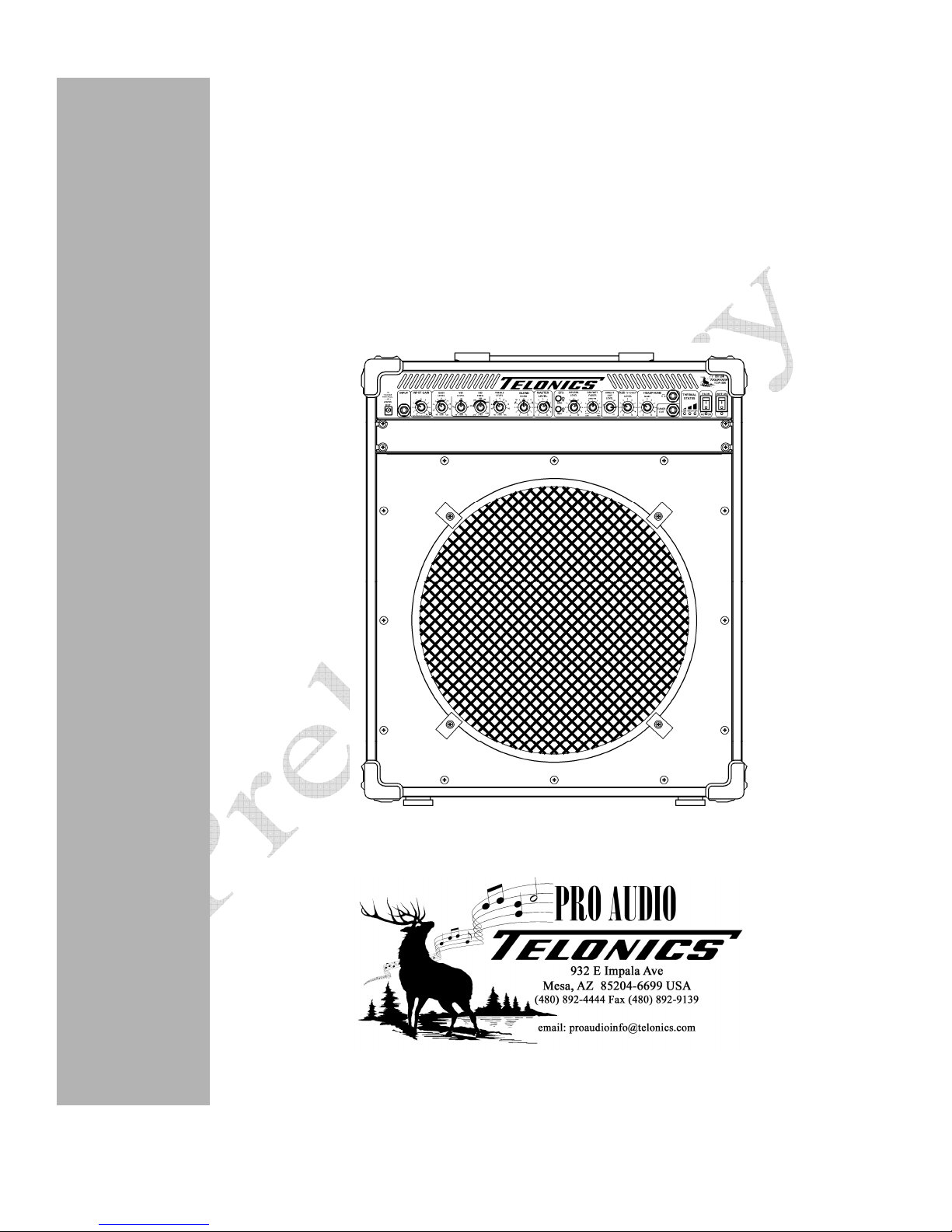
Telonics TCA-500 Combo Amp
8
PB-009289 Rev _ PRELIMINARY
TCA-500
C
OMBO
A
MP
C
ONTROL
F
UNCTIONS
,
J
AC S
,
&
I
NDICATORS
:
F
RONT
P
ANEL
(
CONTINUED
)
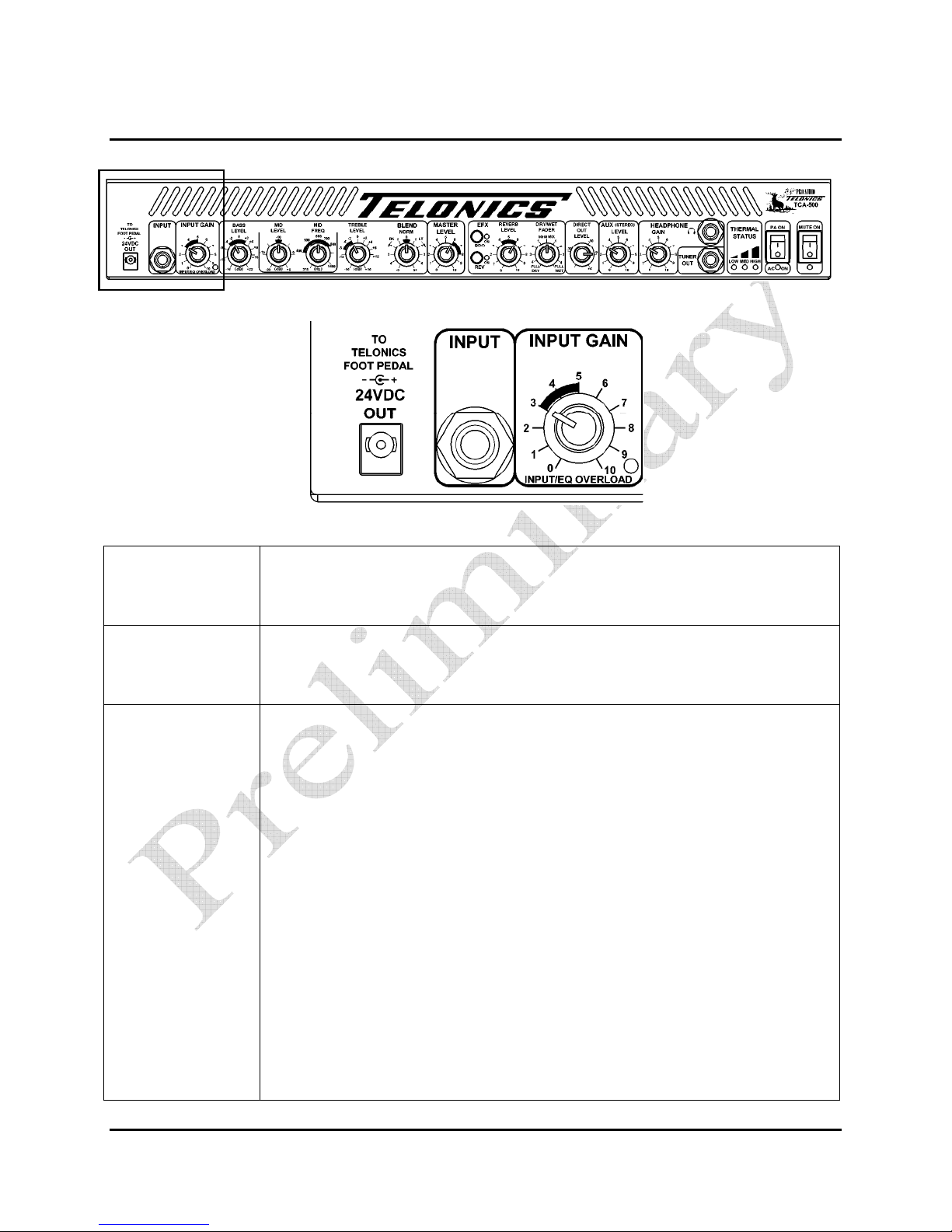
Mid Level
(continued)
Since the mid-range frequencies are tiring to the human ear, it is almost always
necessary to CUT or reduce them. The Mid Frequency control allows the user to
choose the center frequency at which the mid frequencies are reduced, to suit his
or her ear.
The following text describes how the Mid Level and Mid Freq
controls should be set for steel guitar:
i) We assume the Input Gain control has already been set. Set the Bass
Level control to 0, the Treble Level control to 0, the Blend control to 0
and the Master Level control to 2. All effects should be OFF.
ii) No set the Mid Level control fully clock ise (+5) and set the Mid Freq
mid ay (600 Hz). Note hen you pick a string the Overload LED may
flash; don’t adjust the Input Gain control. Note that the overload
monitoring circuitry monitors both the output of the gain section and
the EQ section; because e’ve set the Mid Level control to full boost it
causes the overload.
iii) Ensure the combo speaker is pointed to ards your ear. Pick one or t o
strings in the center string grips and slide the bar over the normal
range of the fret board you ould use. As you are doing this, t eak the
Mid Freq control up and do n around the 400 to 800 region; it’s handy
to have a friend rotate the Mid Freq control as you play. At one point
over the region you might possibly notice, no matter here you are on
the fretboard, a ‘honky’ midrange sound is heard that’s a little
unpleasant on the ear. It does take practice and time to learn ho to
detect this point, so don’t be concerned if it’s not clear the first time
you attempt this. Note the Overload LED may help detect this point,
quite often it flashes more as you hit area’s here’s there’s more
resonance.
Once you have found the honky, excessive ‘middle’ sounding frequency,
rotate the Mid Level control to around the 10 o’clock position (-12dB). As
you play your guitar tweak the Mid Level control up and down around this
point until it sounds balanced in the mid range. Generally, the most
suitable setting is between -15 dB and -12 dB for most people. Don’t
worry about setting the bass and treble controls until you’re happy that the
mid range is the best it can be.
Always, Always, make the above adjustments with the Bass and treble
controls at zero.
Mid Frequency Sets the frequency at which the Mid Level control has an effect. Several
frequency intervals between 375 Hz and 1400 Hz are marked. Its effect is
determined by the setting of the Mid Level control. Proper adjustment is achieved