Telonics Multi-Taper User manual

FP-100 Foot Pedal PB-008427 Rev G
October 14, 2015 Page 1 of 22
Multi-Taper © “Foot Pedal”Audio Control System
Patented
Typ cal FP-100 Conf gurat on
Copyright Notice
Copyright 2015 Telonics, Inc.
All Rights Reserved.
This device is fully covered by a ultiplicity of patents, both granted and pending.
No part of this publication ay be copied without the express written per ission of Telonics, Inc.,
932 E. I pala Ave., Mesa, AZ 85204.

FP-100 Foot Pedal PB-008427 Rev G
October 14, 2015 Page 2 of 22
Multi-Taper © “Foot Pedal” Audio Control System
General Description:
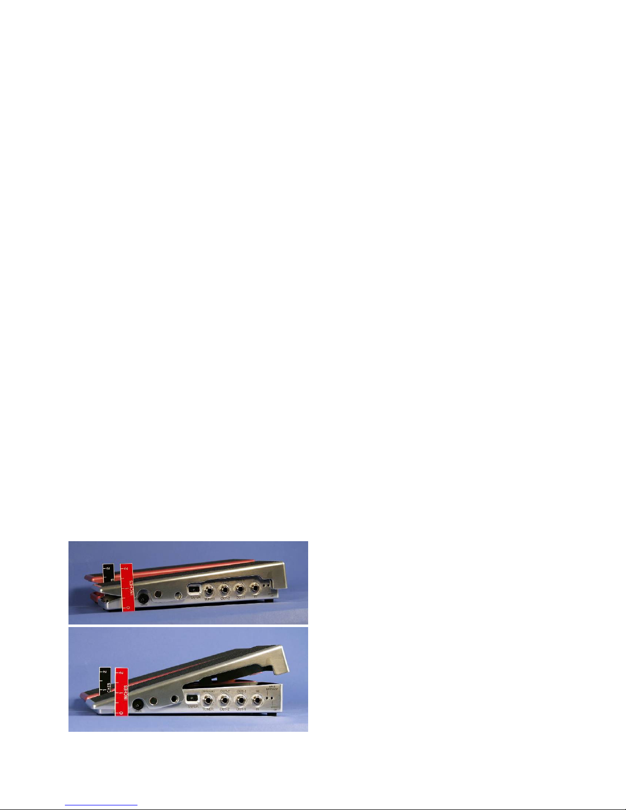
Th s “pedal” s actually a fam ly of advanced technology volume and/or aud o effects control
systems based upon a ser es of revolut onary technolog es developed by Telon cs, Inc. Th s system
takes the mechan cal form of a convent onal foot pedal wh ch can be conf gured w th the
axle/p vot po nt nstalled n what has h stor cally been called “h gh” or “low” conf gurat on
(although th s h stor cal term nology s st ll used, the actual phys cal he ght s “low” regardless of
the p vot po nt chosen). It can be used as a foot pedal of the s mplest form; however t conta ns
techn cal capab l t es wh ch far exceed those of any currently ava lable aud o dynam cs control
dev ce. The bas c model ncludes accurate emulat ons of v rtually all aud o tapers of mechan cal
potent ometers (“pots”) used n the past, as well as the aud o control “taper” of all popular
electron c foot pedals. It also ncludes one or more recently developed tapers wh ch add
capab l t es related such th ngs as ga n and susta n – wh ch have not been ava lable to mus c ans n
the past. (Add t onal repl ca tapers or custom tapers can be factory nstalled v a the USB port).
Tapers are selectable by means of a d g tal sw tch on the s de of the un t near the nput and output
jacks. Th s patented control system does not ut l ze potent ometers, encoders or l ght dev ces of
any type. There are no components to phys cally wear out.
It ncorporates the latest technology n low-no se, analog h gh headroom ampl f cat on - n a class
w th the latest except onal dynam c response stud o-grade ampl f ers, wh le preserv ng the warmth
of v ntage tone. L ke all Telon cs equ pment, t s fully analog. The s gnal cha n s never d g t zed,
therefore A/D or D/A no se s Not added to your s gnal. The FP-100 system does not mod fy your
tone (unless you load down your p ckup w th the Impedance Control). In terms of frequency
response, t s “flat”, or “transparent”. You may “th nk” t boosts the h gh frequency response, but
t Does Not. It s mply allows you to hear what has always been there, but was attenuated by your
system pr or to nstall ng the FP-100. It s fully buffered, prevent ng no se from externally
connected tuners and other dev ces from enter ng the s gnal cha n as well as prov d ng safety from
system malfunct on due to shorted or nterm ttent cables. A full-t me tuner output allows tun ng
w th the pedal n any pos t on, nclud ng the “off”/m n mum pos t on. It s factory programmed v a
a m n ature USB port. Subsequent software updates and add t onal capab l t es may be uploaded
v a th s USB port. The FP-100 s mach ned from sol d alum num b llet block. It w ll not skate
around the floor w th normal foot movement. It s des gned to accept most popular pedal bar
brackets and attachment dev ces. A patented blue LED pedal-board l ght also nd cates both proper
power and that t s operat ng w th n acceptable parameters. The l ght can also nd cate abnormal
operat on through an nternal error code report ng system.
An opt onal micro-miniature remote sensor is available which assumes full control of the pedal
in terms of treadle movement when plugged n. Th s remote control system opens l m tless
poss b l t es, from mechan cal control by nstruments, to usage by mus c ans who have a phys cal
mpa rment and have been prevented from play ng unt l now. (A remote sensor w ll be suppl ed at
no charge to nd v duals who suffer a phys cal mpa rment wh ch can be a ded by th s remote
control dev ce).
Its nternal c rcu try s well-behaved n terms of power supply connect on, nterrupt on or
d sconnect on, thereby m n m z ng no se wh ch m ght annoy l steners or poss bly damage speaker
systems. Th s s no garage-shop hobby st toy. It s the culm nat on of years of research, des gned

FP-100 Foot Pedal PB-008427 Rev G
October 14, 2015 Page 3 of 22
and hand-bu lt n the U.S.A. by lead ng and nternat onally recogn zed aerospace eng neers,
techn c ans, assemblers and mus c ans n a state-of-the-art fac l ty n Mesa, Ar zona by Telon cs,
Inc., an establ shed leader n sc ent f c nstrumentat on and commun cat ons s nce the 1970’s.
Dependab l ty, long-term rel ab l ty, performance and value are paramount n th s pedal/system.
Serv ce, support and adv ce s always as close as the telephone or e-ma l.
Telon cs, Inc. s well known by sc ent sts world-w de for the manner n wh ch we stand f rmly
beh nd our products on a personal bas s. Please contact us w th any quest ons you m ght have, we
nv te des gn comments and are open to any and all suggest ons:
dave@telon cs.com soph e@telon cs.com stacy@telon cs.com
TEL: 480 892-4444 ext. 122 or ext.102 FAX: 480 892-9139
www.telon cs.com
Mechanical
Pedal:
Material: CNC m lled 6061-T6 Alum num w th hardened bear ng surfaces
Axles are o l-hardened (O1) tool steel, 55-60 C-scale Rockwell
Finish: Heavy hard anod zed (M l-A-8625 Type II, Class 2, 0.002”)
ettering: Laser-engraved (all mark ngs are burned through the hard
anod ze coat ng. No pa nts or nks are used on the product,
mark ngs w ll not smear or wear off.)
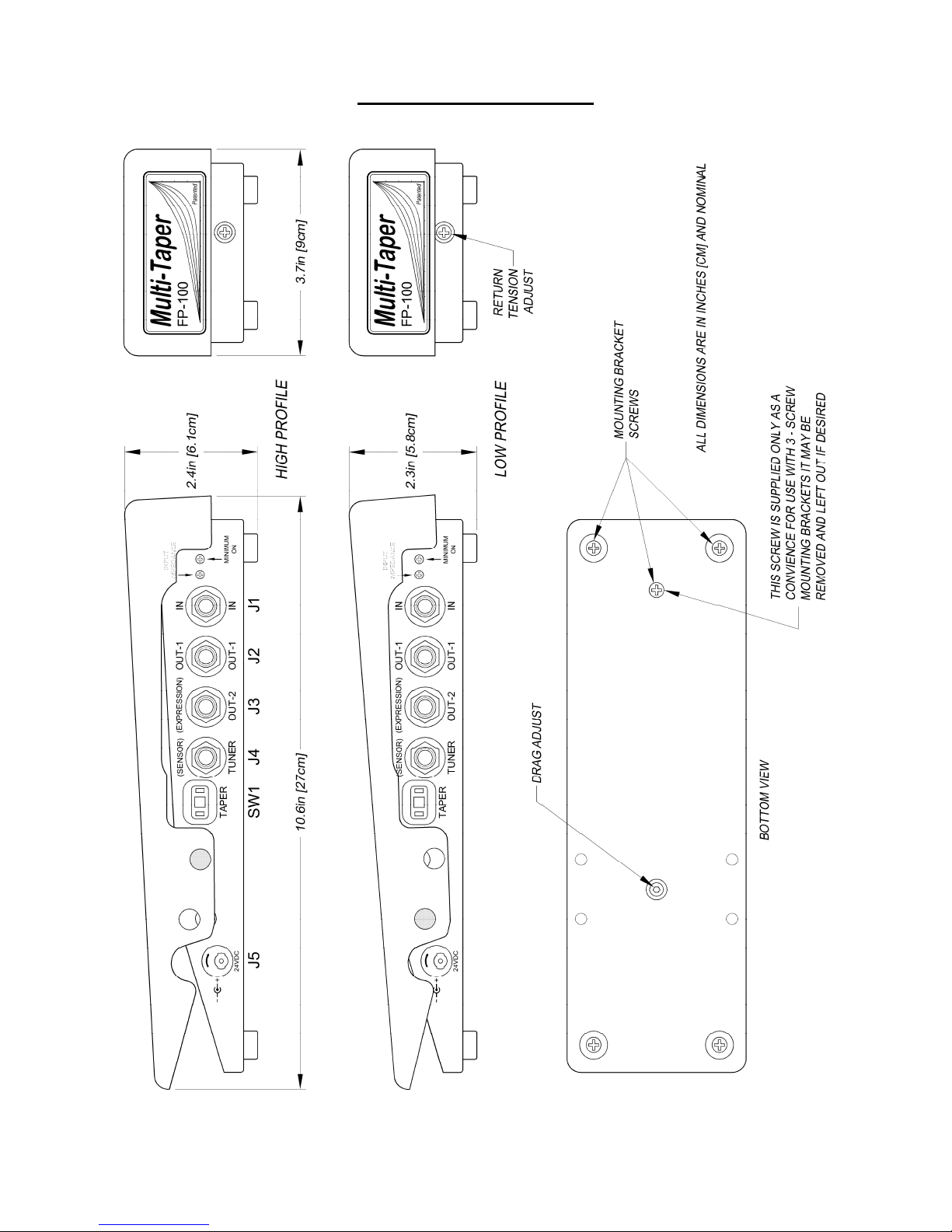
Outline
Dimensions: 10.6L x 3.7W x 2.4H n. (27L x 9W x 6.1H cm)
Weight: 2.35 lb (1.06 kg)
Optional External Sensor:
Size: 0.8L x 0.9W x 0.125H n. max mum
(20.3L x 22.9W x 3.2H mm) max mum
Connector: ¼” TRS male “Stereo Plug” (T p-R ng-Sh eld/Sleeve)
FP-100 Foot Pedal PB-008427 Rev G
October 14, 2015 Page 4 of 22
Mechanical Adjustments:
Axle Position – History and Considerations:
In order to d scuss the d fferences between what have been trad t onally called
“h gh” and “low” pedals, one must f rst def ne whether we are d scuss ng old,
trad t onal pot pedals (and some of the very early “l ght” pedals), or, the newer
generat on of electron c pedals.
H stor cally, the early pedals were, ndeed made n a truly “h gh” and “low”
vers on, and n fact, the h gh vers on was ndeed “taller” than low vers on –
wh ch prompts the d scuss on regard ng longer and shorter legs, brush ng the
undercarr age of the steel w th a knee, etc.
BUT, often overlooked is the fact that the axle in older “high” pedals was/is
positioned farther forward on the pedal than the “low” models.
D sregard ng the actual pedal he ght factor, and more mportant to many players,
s that hav ng the axle/p vot po nt at a d fferent po nt d rectly nfluences the
RANGE of MOTION of the players ankle for the same angle range of the
movable top/treadle on the pedal. As a result, the two types of pedals have a
d fferent feel. Th nk of t as a ch ldren’s teeter-totter. The older “h gh” pedals are
more l ke a normal teeter-totter w th the p vot po nt close to the m ddle.
The older “low” pedals are more l ke a teeter-totter w th the axle moved back
toward the back (or toward your heel on the pedal). Also note that as you move
the axle farther and farther back (toward the heel) w th the pedal n the fully
“heel down” cond t on, two th ngs happen:
1. The heel of your foot gets lower and lower respect to the front of your foot,
and,
2.
You get a leverage effect. Depend ng upon how far back the axle s placed.
You no longer have a one-to-one relat onsh p, that s, f you move the back of
the pedal 1/8 of an nch, the front of the pedal moves more than 1/8th of an
nch…….
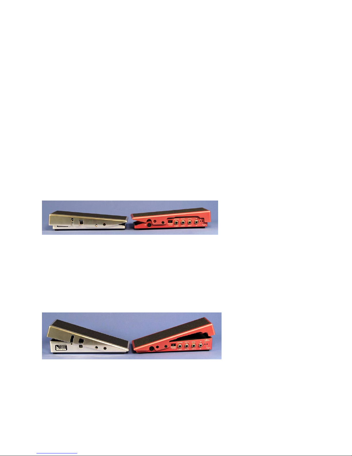
Fast forward to the new generat on of electron c pedals.
Because they do not have large pots n them,
there s no need to bu ld a pedal any h gher than
the older “low” pedals n order to change the
p vot po nt of the pedal by mov ng the axle
forward or backward. As a result, there s very
l ttle d fference (only a few m ll meters) n what
are st ll somet mes called “low” or “h gh”
models. Th s var es by manufacturer between
the r two models. In the case of Telon cs pedals,
there s no longer a need to produce and stock
two models as one pedal covers both cond t ons;
the axle can be moved to e ther pos t on to su t
the player w thout chang ng the over-all he ght to
any apprec able degree.
FP-100 Foot Pedal PB-008427 Rev G
October 14, 2015 Page 5 of 22
So w th Telon cs pedals, the aspect of pedal he ght s no longer appl cable w th
respect to players hav ng longer or shorter legs. The only s gn f cant d fference
between the two axle pos t ons n new pedals s therefore the axle placement.
Th s axle placement becomes mportant to the player w th regard to h s or her
comfort w th respect to h s or her preferred/comfortable range of ankle mot on.
Th s has somet mes bo led down to whether the player s younger or older, and
whether they prefer to wear shoes (or boots) w th low or h gh heels when they
play.
There s a generally accepted common range of mot on for the ankle wh ch the
major ty of players f nd to be most comfortable. It s therefore necessary to
choose an axle pos t on wh ch w ll correspond to a comfortable range of mot on
for the type of heel that you prefer to wear wh le play ng, s nce the heel controls
the angle of your ankle when your shoe s n a g ven pos t on. People generally
want the r foot to be comfortable when the pedal s at full “heel-down”/when the
pedal s at m n mum volume. AND, they want the r foot to feel comfortable as
they cont nue the pedal’s range of mot on on through to full “toe-
down”/max mum volume pos t on.
In general we f nd that people who wear boots to play n (or women w th heels)
prefer the axle to be n the
rearward pos t on (closest to the
back of the pedal) – wh ch s
commonly st ll called a “low”
pedal. A h gher boot or shoe
heel ra ses the back of the
player’s foot, and plac ng the axle toward the back of the pedal drops the rear of
the treadle a correspond ng amount so the foot s not “po nted” as far forward.
Unless th s s done, the ankle may have to be rotated uncomfortably (for some
people) forward when the toe s fully down. As an observat on, some players
have also remarked that the leverage of such a “low” pedal can feel a b t
“touch er” s mply because of the leverage change when the axle s moved
toward the rear of the pedal.
Players who wear relat vely flat soled shoes (or people who play barefoot),
typ cally prefer hav ng the
axle/p vot po nt near the center
of the pedal. Th s type of pedal
s st ll often called a “h gh”
pedal through force of hab t or
convent on. We have also
found that stand ng 6-str ng
gu tar players, bass players, f ddlers, etc, typ cally prefer pedals w th the axle
placed near the center of the pedal (they also prefer to have and use the Telon cs
fr ct on lock/clutch so they can eas ly move the r foot on and off the pedal
w thout acc dentally chang ng the volume sett ng, or have the pedal change due
to the stage v brat on from woofer v brat on or stomp ng – C6th players also
often prefer th s type of clutch so they can move the r foot on and off the volume
pedal when us ng two feet on the r gu tar pedals).
FP-100 Foot Pedal PB-008427 Rev G
October 14, 2015 Page 6 of 22
There are certa nly more axle cons derat ons, but I hope th s nformat on s of
some ass stance to you. Once you get past "h gh" or "low" axle placement, you
are actually just scratch ng the surface of mportant cons derat ons for a
profess onal volume/swell control pedal.
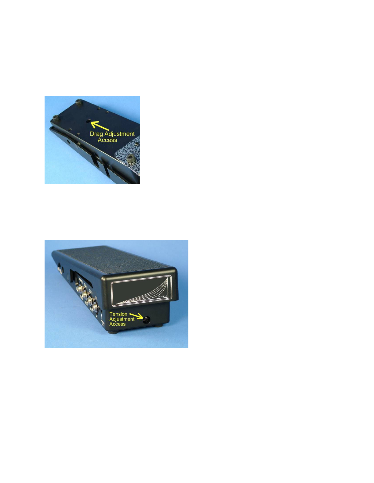
Both DRAG (ease of treadle movement) and TENSION (treadle
return tens on) are ndependently adjustable to su t the
user. Please refer to the photos and draw ngs prov ded n
th s document:
Drag: A 3/16 (0.187) nch “Allen”-type HEX head cap
screw located on the bottom of the pedal prov des a
means of custom z ng the Drag exper enced dur ng
pedal movement. A 3/16 nch HEX wrench s suppl ed
from the factory for th s adjustment. Note that th s
adjustment s very sens t ve. Turn ng th s screw only a
sl ght amount w ll greatly change the ease of pedal
movement. A fract on of a turn Clockw se (CW) w ll ncrease drag
(make the treadle more d ff cult to move). Conversely, a small
amount of adjustment n the Counterclockw se (CCW) d rect on w ll
decrease the drag, mak ng the treadle eas er to move.
Tension: A Ph ll ps-head screw on the front face of the base
adjusts treadle return Tension (lift). It
can only be properly adjusted f the
Drag adjustment s fully rel eved (set to
m n mum drag). It exh b ts a very w de
adjustment range, requ r ng several
turns n e ther d rect on to make an
apprec able d fference. It has been
factory adjusted w th the drag
adjustment set to m n mum. If you
should dec de to adjust t, f rst be sure
the Drag screw s turned CCW to
m n mum drag, make any des red
tens on adjustment, then re-set the Drag
to complete the process.

FP-100 Foot Pedal PB-008427 Rev G
October 14, 2015 Page 7 of 22
Bracket
Interface: The FP-100 s des gned to nterface w th most popular pedal bar
brackets wh ch ut l ze e ther two screws, or a
tr angular three hole pattern. The screws wh ch
attach the two front feet are sl ghtly longer n
order to allow for the th ckness of a bracket.
To mount a two-hole bracket, remove the two
front feet and mount t us ng the two screws
w th the rubber feet st ll attached (under the
bracket).
To attach three-hole brackets, remove both front
feet AND the s ngle screw just beh nd them
(sl ghtly toward the center of the pedal). Attach
the bracket us ng all three screws.
Note: This center screw is provided solely for
bracket use, it serves no other purpose and can
be removed if desired.
Note: The brackets from some manufacturers
are not produced with consistent hole pattern
location and spacing. In some cases it may be
necessary to enlarge a hole or holes, or even
re-drill the odd hole in a bracket.
(Refer to the p ctures show ng var ous types of pedal bar mount ng brackets, no mod f cat ons to
these brackets were necessary.)

FP-100 Foot Pedal PB-008427 Rev G
October 14, 2015 Page 8 of 22
Electrical:
Power Supply: UL and CE approved transformerless sw tch ng power supply*
PS-1: 100-120 VAC, 60 Hz (US power)
2.5L x 1.1W x 1.7H n. (63L x 26.6W x 43.3H mm) (typ cal)
<3.5 oz (<100 g)
PS-2: 90-264 VAC, 47-63 Hz (Worldw de usage)
2.9L x 1.7W x 1.3H n. (74L x 43.5W x 34H mm)
<6 oz (<170 g)
* Note: Two (2) power supply opt ons are ava lable:
1. PS-1 - suppl ed w th a lock ng plug wh ch f rmly
attaches to the pedal’s power jack (J5) and cannot be
pulled out acc dentally.
(The PS-1 un ts plug n 90 degrees to an AC
“ma ns” power str p and occupy only one outlet slot.
They are very small, l ghtwe ght {<3.5 oz., <100g}
and do not em t the 50-60 Hz AC hum-produc ng
electr cal f elds normally assoc ated w th the older
transformer-type “wall-wart” power suppl es.)
2. PS-2 Internat onal model, w th nterchangeable
prongs wh ch snap nto place for nternat onal use.
Suppl ed w th convent onal coax al DC m n -plug
end wh ch allows the user to plug and unplug the
pedal eas ly.
(L ke the PS-1 un ts descr bed above, the PS-2
Internat onal un ts do not exh b t the 50-60 Hz AC
hum-produc ng electr cal f elds normally assoc ated
w th the older transformer-type “wall-wart” power
suppl es.)
St ll relat vely l ghtwe ght, the PS-2 power suppl es
are sl ghtly larger than the PS-1 power suppl es.

FP-100 Foot Pedal PB-008427 Rev G
October 14, 2015 Page 9 of 22
Jacks and Controls:
NOTE: All inputs and outputs are buffered and isolated such that shorted or
Intermittent Cables will not damage the pedal, interfere with other
cable functions or adversely effect signal levels
Inputs:
Monaural models are suppl ed w th a *dual-funct on nput jack (J1,
refer to Outl ne Draw ng on page 18) and assoc ated c rcu try wh ch
w ll accept a convent onal ¼” TS plug for convent onal unbalanced
p ckups.
*It w ll ALSO accept standard TRS plugs for BALANCED l ne nputs
(for future very low-no se balance-wound p ckups.
In Stereo models, nput jack J1 accepts a convent onal ¼” TRS stereo
plug.
Monaural (MONO) Models:
IN-Unbalanced:
Input jack (J1) accepts standard ¼” TS-type
aud o plug for all convent onal unbalanced, h gh mpedance p ckups.
The nput jack (J1) ALSO accepts ALANCED nputs as follows:
IN-Balanced:
In ant c pat on of forthcom ng advances n p ckup
des gn, Input jack (J1) also accepts standard ¼” TRS-type plugs for
both h gh and low mpedance balanced p ckups. Its assoc ated c rcu try
automat cally detects the type of nput (balanced or unbalanced) and
requ res no sw tch ng or other user ntervent on.
Stereo Models:
IN-Stereo, unbalanced:
Input jack (J1) accepts standard ¼” TRS-
type INPUT jack for two ndependent nput s gnal sources us ng
unbalanced, h gh mpedance p ckups. W r ng connect ons are:
T p = Left Channel
R ng = R ght Channel
Sh eld = Common s gnal ground
24VDC (power):
J5 s the DC power nput jack. It may ONLY be
used w th a factory suppl ed power supply. It w ll accept e ther the
standard smooth-barrel DC power plug, or the opt onal ¼-turn lock ng
type DC power plug. The non-lock ng plug makes t easy to remove the
power supply for transport, wh le the lock ng tabs prevent the plug
from be ng acc dentally be ng pulled loose.
The FP-100 is specifically designed such that unpleasant loud pops
which might damage speaker systems are NOT generated when (or if)

FP-100 Foot Pedal PB-008427 Rev G
October 14, 2015 Page 10 of 22
the power plug is suddenly pulled out while the amplifier systems are
on/live
OUTPUTS
OUT-1:
n monaural models, J2 (refer to Outl ne Draw ng on
page 18) s a convent onal ¼ nch TS jack w th ts aud o output level
buffered, and controlled by treadle movement. Aud o taper select on s
controlled by the taper program preset sw tch as well as by a user-
selected “m n mum OFF” sett ng wh ch the user may adjust for each
nd v dual taper.
OUT-2:
n monaural models, J3 (refer to Outl ne Draw ng on page
18)) s also a convent onal ¼ nch TS jack. Th s jack prov des an output
wh ch s dent cal to that of OUT-1, and s normally used to prov de a
second dent cal, phase-coherent s gnal source for players who w sh to
feed the r s gnal to a second preamp, combo amp or spec al effects
system. (Note: Th s s Not the case when the express on opt on s
nstalled – see below.)
In stereo models, J2 and J3 prov de nd v dual buffered, analog s gnal
cha n outputs for Left and R ght Channels respect vely.
The EXPRESSION option in Telonics mono pedals:
The EXPRESSION opt on s an added funct on and costs extra. It must be
nstalled at the t me the pedal s n t ally bu lt; t cannot be added later! It s
nstalled only n MONO (monaural) pedals, e ther the mono PRO or the
standard mono models.
The express on opt on essent ally adds one add t onal capab l ty to the
pedal: In add t on to controll ng the normal volume control funct on, th s
added DC-control-voltage-output can be used to control any effects un t
wh ch s des gned to accept a control voltage suppl ed by an external
express on pedal. W th the EXPRESSION opt on nstalled, as you push the
treadle forward, the volume at the output of the pedal s ncreased n the
normal manner; s multaneously the DC express on control voltage from
OUT-2 w ll cause the external effects un t to ncrease the ntens ty of ts
effect.
Effects un ts that people currently use are ones l ke the Fractal-Axe, but the
Telon cs pedal also works well w th older equ pment as well, such as the
Lex con MPX-1. There are st ll lots of them around and they can be
programmed to use an effects pedal to control them. Most such EFX un ts
can also be programmed as to how fast you want the effect to ncrease
(s m lar to the way the volume s controlled n all Telon cs pedals for
m n mum and max mum levels). As an example, w th the express on
opt on nstalled, a Telon cs pedal could be used to control an nstrument’s
volume, but could also be connected for EXPRESSION output to an
external effects un t wh ch s set for tremolo effect. W th the pedal n the
off pos t on (no volume), the player would have no volume out and no
tremolo effect. But, as the pedal’s treadle s depressed, the volume w ll

FP-100 Foot Pedal PB-008427 Rev G
October 14, 2015 Page 11 of 22
beg n to r se, w th a h nt of the effect be ng heard. Then, as the treadle s
depressed more, the volume w ll ncrease and the tremolo effect w ll
become more pronounced. Toward the full toe-down pos t on, the volume
w ll be near ng max mum and the tremolo w ll be very pronounced. The
pedal w ll work the same w th any effect or any comb nat on of effects you
m ght have programmed nto an external effects un t wh ch s des gned to
be controlled by an external 0-5 VDC control voltage.
The express on voltage suppl ed by the FP-100 pedal s the ndustry
standard 0 to 5 Volts DC. Make sure your EFX dev ces w ll accept th s
voltage range and work properly w th t. The Fractal AXE, the Lex con
MPX-1, and most of the h gher-end EFX un ts are f ne w th t, but you w ll
need to check the manuals for the part cular un ts you are us ng.
When the express on opt on s bu lt nto these pedals, the OUT-2 jack s no
longer ava lable as an aud o output jack, but rather becomes the Express on
voltage output jack! As such, t does not perform any other funct on. In
other words, f you wanted to use th s pedal as a “spl tter” (by connect ng
your gu tar or other s gnal source to the INPUT jack and us ng the OUT-1
and OUT-2 to feed two d fferent ampl f ers), you sacr f ce that capab l ty
when you have the Express on opt on. Thus, f you need a 2nd output jack
more than an Express on output, don’t order the Express on opt on. You
cannot return a pedal that has the Express on opt on n t, s nce the
Express on opt on cannot be removed once t s nstalled n the pedal.
In summary, add ng the EXPRESSION opt on essent ally makes your one
pedal do the work of two pedals s multaneously: one volume pedal and one
express on pedal. Some players (both steel gu tar and 6-str ng gu tar
players), apprec ate th s capab l ty. There s no other pedal wh ch w ll do
all these th ngs.
EXPRESSION:
In un ts w th the factory nstalled Express on opt on,
“OUT-2” s a fully-funct on ng express on control jack wh ch requ res a
TRS plug. OUT-2 does not prov de an aud o output when the
express on opt on s nstalled; t ON Y funct ons as an express on
output jack.
W r ng follows ndustry standard protocol:
T p = Express on Voltage (L near) Output (0 - 5 VDC)
R ng = DC Voltage nput from external EFX un ts
(However External Voltage s Not Used by FP-100)
Sleeve = Common DC Ground
NOTE: The DC Expression Control Voltage is at zero volts when the
treadle is at Volume Minimum (normally heel-down) and at +5 VDC
when the treadle is at Volume Maximum (normally toe-down)
FP-100 Foot Pedal PB-008427 Rev G
October 14, 2015 Page 12 of 22
TUNER/sensor:
J4 (refer to Outl ne Draw ng on page 18) s a dual-funct on ¼”
jack, prov d ng a full-t me TUNER OUTPUT s gnal, regardless of pedal position
(¼” TS-type). Th s allows the user to cont nuously mon tor tun ng w th the pedal n
any pos t on, nclud ng the full/m n mum off pos t on. This output is buffered and
isolated It will not allow the noise from digital tuners to get back into the system
Th s jack (J4) s also used for the opt onal Telonics Miniature Remote Sensor
(TMRS). It accepts the ¼” TRS-type plug on the TMRS cable and automat cally
commun cates w th the sensor when the user chooses to use the TMRS nstead of the
foot pedal to control volume.
When the remote sensor is plugged into J4 it automatically assumes full control of the
pedal, replacing the control function of the moveable foot platform (treadle)
NOTE:
In order for the pedal to recogn ze the sensor, t must be plugged nto the
(SENSOR)/Tuner jack on the pedal (next to the taper select on sw tch) - w thout POWER
APPLIED TO THE PEDAL.
The pedal must then be powered up AFTER the sensor cable has been plugged n.
(If you leave the sensor plugged nto the pedal after use and the pedal has been powered
down, you may s mply apply power to the pedal n the normal manner and the sensor w ll
funct on properly).
CONTRO S and INDICATORS:
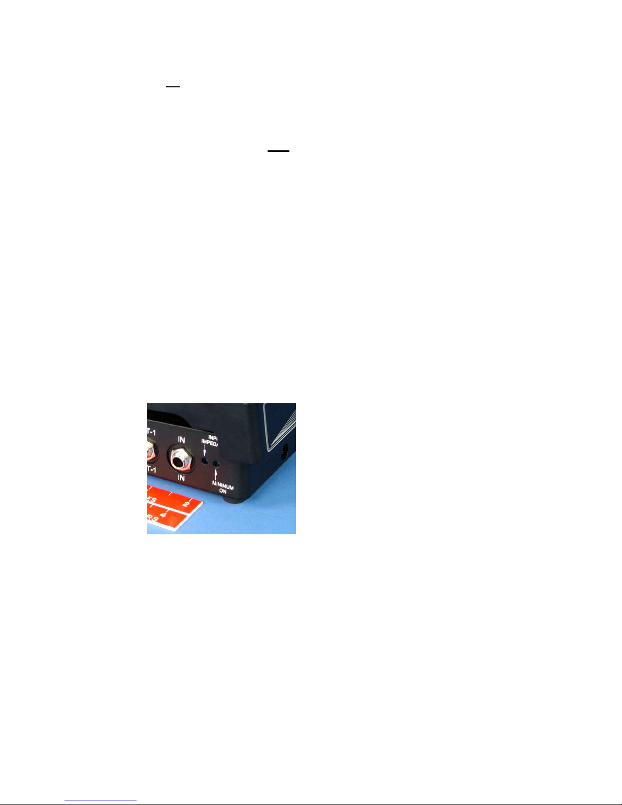
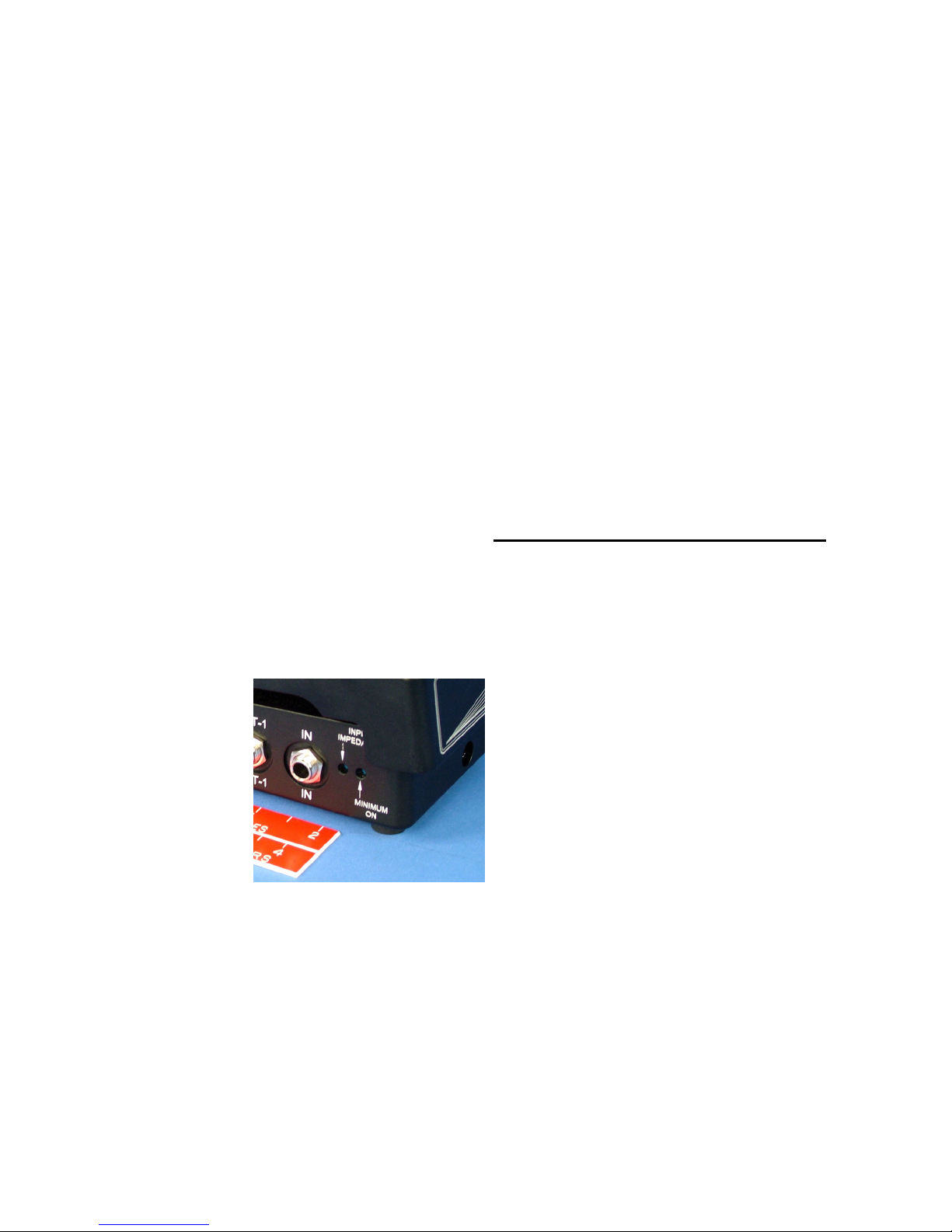
INPUT IMPEDANCE:
A m n ature screwdr ver 240 degree rotat on
adjustment s prov ded on the r ght s de of the pedal (near the front, mmed ately
forward of the INput jack J1) wh ch controls the
nput mpedance of the low-no se, h gh headroom
nput ampl f er. Please utilize the miniature
screwdriver adjustment tool provided and take
care to avoid excessive force. Th s control s set
to max mum (fully clockw se) as suppl ed from the
factory. In the past, players have unknow ngly
(and n a few cases know ngly), employed
mpedance controls as a “poor man’s tone control”,
lower ng the nput mpedance to “load” the p ckup
and reduce ts h gh frequency response. If des red,
that can st ll be done w th these pedals, however the pract ce “swamps” or reduces the
output of the p ckup, reduces ts resonant character st cs, d m n shes ts dynam c
character st cs and reduces ts frequency response. (Some players are accustomed to
the resultant “muted” or “nasal” sound qual ty when the r p ck-ups are mpedance-
loaded, and they ntent onally use th s adjustment to subtly color the r sound.)
Mus c ans tend to get together and compare hardware by subst tut on and often ( f not
generally) come to false or unrepeatable and/or confus ng conclus ons. The
equ pment be ng compared (var ous nstruments w th d fferent p ckups, d fferent
ampl f ers w th vary ng nput mpedances, d fferent pedals be ng us ng w th
preampl f ers hav ng mpedance controls, etc), w ll produce d ffer ng/ nconclus ve
results w th var ous models and types of p ckups, as they w ll exh b t d fferent
character st cs when loaded w th the same mpedance. Th s s why a g ven dev ce
may y eld wonderful results w th one persons’ nstrument, but has l ttle effect, no
effect, or even an adverse effect when used w th another nstrument
FP-100 Foot Pedal PB-008427 Rev G
October 14, 2015 Page 13 of 22
Its not rocket science, it’s just that there may be a large number of complex
variables In such cases, very simple tests can be very misleading.
If you are using a studio-quality preamplifier with proper tonal shelving
characteristics such as the Telonics preamps, it is suggested that the user
leave this control at the factory setting (maximum clock-wise, very high
impedance/little or no pickup loading) and allow the preamplifier to provide
control of tonal characteristics without inhibiting the performance of their
pickup
If convent onal ampl f ers are used, we suggest that th s control be used very
spar ngly, and only after all other tonal poss b l t es on the ampl f er are
exhausted. Nonetheless, th s control s prov ded for those players who have
played that way for many years and feel that they cannot ach eve the r
nd v dual sound any other way.
Note that this control is both small and delicate. Please utilize the
miniature screwdriver adjustment tool provided and take care to avoid
excessive force. The entire range of adjustment occurs over
approximately a 240 degree range. If it were a clock-face, maximum
pickup loading would occur at about 8:00 o’clock (fully CCW) and
minimum loading at 4:00 o’clock (maximum CW). We suggest that you
check and make sure that it is fully clockwise (CW) when not being used.
You can watch the pocket clip on the adjustment tool provided with the
pedal while turning to get an idea of where it is set.
MINIMUM ON:
An adjustment access hole s prov ded mmed ately
forward of the Input Impedance access hole on the r ght front corner of the
pedal. Th s adjustment controls the minimum level of audio signal which
is allowed to pass through the pedal when
the control platform is fully back, or n the
MINIMUM sound level pos t on (of course
th s w ll reverse f you are us ng the
Reverse Taper option). Un ts are factory
adjusted such that the output level appears
OFF to the ear of the average player when
the pedal s fully back (the most popular
adjustment sett ng for the major ty of
mus c ans). The adjustment range of th s
control s determ ned by software. (It s normally set correctly at the factory
for most users, however t can be eas ly adjusted by the user us ng the
m n ature black screwdr ver tool suppl ed w th the pedal.) Please use the
small screwdriver tool supplied, this is a delicate control and can be
damaged by using large screwdrivers It turns easily and only rotates a
total of about 240 degrees, DO NOT force it beyond its stops at each end of
its rotation The adjustment procedure s outl ned n the follow ng
paragraphs.

FP-100 Foot Pedal PB-008427 Rev G
October 14, 2015 Page 14 of 22
HOW TO CHANGE the M n mum ON sett ng for a g ven taper:
If you f rst understand a b t about how the system operates when you change the minimum
on adjustment, the operat on w ll go much more smoothly.
When the pedal s f rst powered up, the “bra n” ns de the pedal “sees” the last sett ng that
someone made w th th s control. When you select a g ven taper w th the selector sw tch, t
checks ts memory for the last sett ng used w th that taper, and mplements t. Then t
beg ns to “look at”, or check the minimum on control to see f you are mov ng t (It checks
for any movement about 60 t mes each second). If the control s not moved, the bra n s
“happy” and noth ng happens.
Now you want to change the setting
The brain has been given a rule, that it is to record your new setting
10 seconds after you stop moving the control.
The instant you move the adjustment, the bra n starts a 10 second countdown – wh ch s
reset to10 each time you move the control. When you f nally stop mov ng the control for a
10 second per od, the bra n wr tes (what t now “th nks” s) your “f nal” sett ng to a
memory locat on assoc ated w th the taper you are us ng. It w ll then recall th s sett ng
each t me you select th s same taper.
Now that you know the rules for how t works, you may not be so surprised when you
move the control for the first time and the volume suddenly changes n t ally.
Let’s th nk about why th s m ght happen; n t ally the volume s set accord ng to the
pos t on of your pedal, as def ned by the taper you have chosen, and mod f ed further by
the last memor zed sett ng of the minimum on control wh ch ts “bra n” pulled from the
current taper’s memory locat on. Now you move the control a b t one way or the other. The
system mmed ately adjusts to the new sett ng!
If you moved the control up, the sound level jumps to the new ncreased level. Conversely,
f you happened to move t down, the sound level abruptly drops to the new level.
Of course after that po nt, you can select any des red level w th great prec s on. Then f
you don’t change the control for 10 seconds, the new sett ng s wr tten to memory and that
sett ng w ll now be the new minimum on sett ng unt l you dec de to change t.
Note that this control is both small and delicate. Please utilize the adjustment tool
provided and take care to avoid excessive force. The entire range of adjustment
occurs over approximately a 240 degree range. If it were a clock-face, the adjustment
range would occur from about 8:00 o’clock (fully CCW) to about 4:00 o’clock
(maximum CW). You can listen to the audio volume while turning it with the pedal
FU Y BACK, (MINIMUM SOUND position) to determine where it is set.
The FP-100 will “remember” this setting and store it in FLASH memory along with the
particular taper you have it set to - 10 seconds after you stop moving the control. That
way, when you recall any taper using the TAPER switch (described below), your desired
minimum-off setting will be preserved for that taper.
The FP-100 will Also write the setting to memory Immediately if you change the Taper
Switch before the 10 second countdown is reached.

FP-100 Foot Pedal PB-008427 Rev G
October 14, 2015 Page 15 of 22
TAPER:
A means to select the des red aud o volume taper s
prov ded n the form of the taper program preset switch wh ch
selects the des red taper by means of
two small buttons on e ther s de of
the d splay w ndow. One button
advances the number, the other
reduces the number.
The factory-suppl ed volume tapers
are as follows:
1 H lton* LED l ght pedal (“new
type” w th small detachable
power supply)
2 Goodr ch* LED l ght pedal (green LED model)
3 Goodr ch* pot pedal (us ng Clarostat type EJA1N116P504A)
4 Emmons* factory pot pedal (us ng class c Allen-Bradley
pot, Type J, JAIN200P504AA)
5 H lton* LED l ght pedal (“old type” w th large permanently
attached Motorola power supply)
6 Telon cs Spec al Susta n Taper
7 s l ke 4, but has added ga n at the end of treadle throw.
8 s l ke 5, but has added ga n at the end of treadle throw.
9 Vacant – other taper may be added n th s pos t on.
0 s reserved as a programm ng pos t on and w ll not respond to
pedal movement.
If a given switch position is unused (currently 9), the output will be
held to a fixed low volume and will not respond to pedal action
* Note: H lton, Emmons and Goodr ch are f ne compan es who produce a good product and
stand beh nd the r products n a commendable manner. The r names are ncluded
solely for compar son of an electron c character st c exh b ted by one or more of
the r pedal models; n th s case, that character st c s measured aud o volume taper.
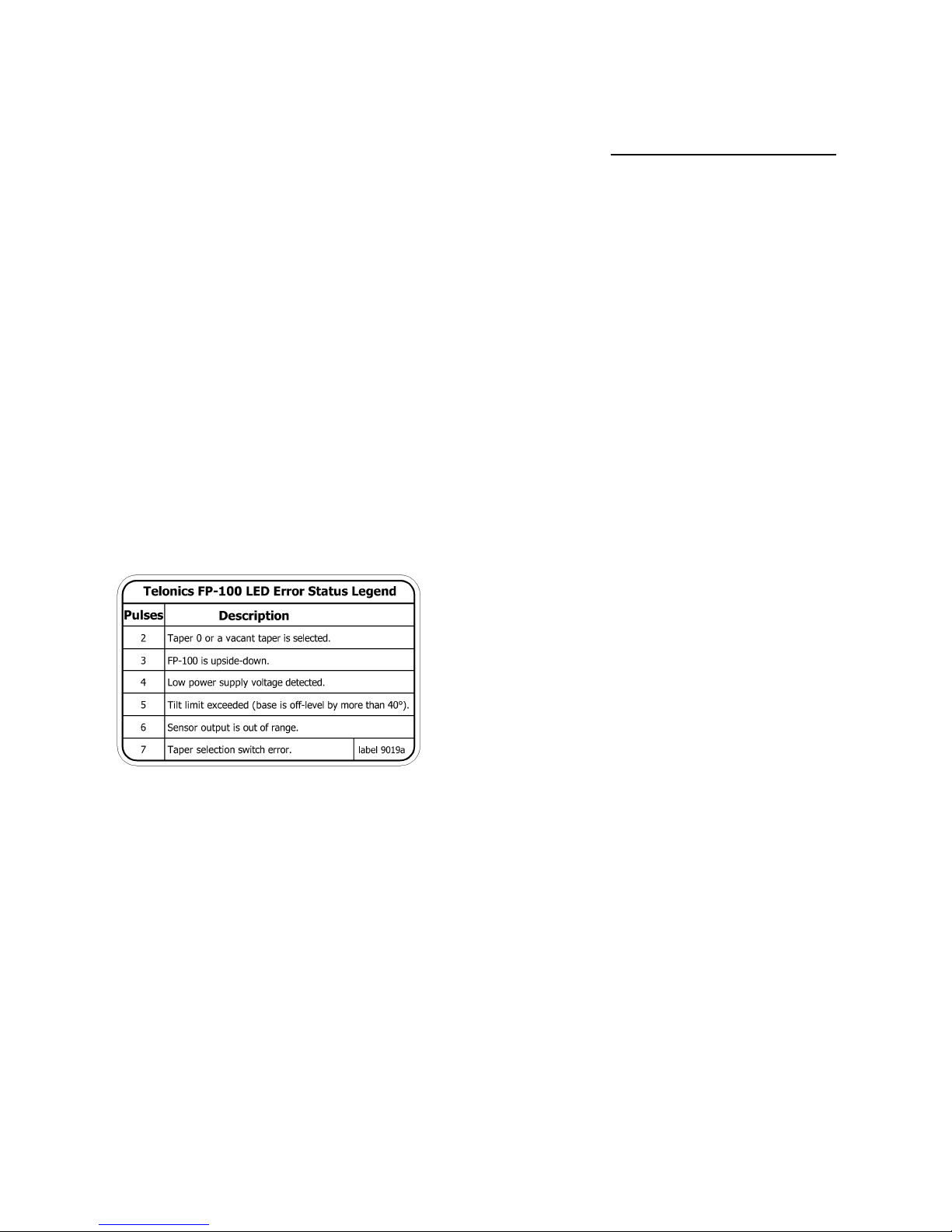
Blue Pedal board ight:
The blue l ght (LED) on the left s de of the pedal serves to llum nate the
pedal board, but t also serves as a v s ble error status report ng nterface
between the user and the m croprocessors n the pedal. If your pedal
ncludes error report ng and status capab l ty F2 f rmware set vers on 2.0
or later, t w ll have a label on the bottom surface wh ch l sts the most
FP-100 Foot Pedal PB-008427 Rev G
October 14, 2015 Page 16 of 22
mportant funct ons. Th s label, along w th an explanat on of these
funct ons s shown below:
NOTE: The user may choose to have the blue ED either ON or OFF
(other than when it reports a problem by blinking).
The des red cond t on may be set us ng the follow ng procedure:
1.
W th the power plug removed, set the pedal on a flat surface and
advance or retard the TAPER sw tch to pos t on “0” (zero).
2.
If you w sh the LED to be normally ON, t lt the top of the pedal
fully forward (max mum ON) and nsert the power plug. The blue
LED w ll come ON, and t w ll normally stay ON from that po nt
forward.
If you w sh the LED to be normally OFF, unplug the power cord,
t lt the top of the pedal fully back (m n mum ON) and nsert the
power plug. The blue LED w ll not come on, and t w ll normally
stay OFF from that po nt forward (unless an error s encountered).
You may then advance or retard the TAPER sw tch to the taper you prefer
and use the pedal normally.
Normally, the blue LED nd cator s e ther always
ON, or always OFF as descr bed n the prev ous
paragraph. However, n later model pedals, t also
serves to not fy the user of var ous cond t ons.
Error or Fault Reporting: If the nternal self-test
rout nes encounter an nternal c rcu try fault,
report ng bad power supply cond t on or other out of
range cond t ons, the LED w ll bl nk rap dly as l sted
on the chart attached to the bottom surface of the
pedal. The var ous cond t ons are nd cated by the number of t mes the
blue LED flashes.
Groups of two (2) pulses nd cate that the taper program preset switch
on the s de of the pedal has been left n an nval d state. These states
nclude Taper 0 (wh ch s used for programm ng funct ons and for turn ng
the LED fully ON or fully OFF), or any sw tch pos t on wh ch does not
currently have a val d taper program nstalled. For example, at the t me of
th s wr t ng, pedals are be ng sh pped from the factory w th taper programs
nstalled n sw tch pos t ons 1 through 8. If the sw tch s nadvertently left
n pos t on 9, the LED w ll beg n to flash two t mes, pause, then flash two
t mes aga n, and so on, unt l the nval d cond t on s rect f ed.

FP-100 Foot Pedal PB-008427 Rev G
October 14, 2015 Page 17 of 22
Groups of three (3) pulses nd cate that the angular report ng system n the
pedal “th nks” the pedal s phys cally ups de down. If the pedal s actually
NOT ups de down, th s could nd cate that the angular sens ng system s
see ng a fault.
Groups of four (4) pulses nd cate that a low power supply output voltage
has been detected. In such case the pedal may not operate properly. Th s
could nd cate that the AC (ma ns) supply s abnormally low or some other
electr cal problem s reduc ng the nternal voltage seen by the electron cs
system n the pedal.
Groups of f ve (5) pulses nd cate that the pedal’s phys cal pos t on s out-
of-range as determ ned by the nternal angle sens ng system. The pedal
can be used at least 30 degrees off-ax s. Th s s common w th some
mount ng systems such as seen n older Emmons Push-Pull steel gu tars.
However f the allowable range s exceeded, th s error w ll be nd cated.
If th s error code were to be nd cated wh le the pedal s perfectly flat on
the floor, th s would mean a poss ble problem ex sts n the angular sens ng
system.
Groups of s x (6) pulses nd cate the nternal sens ng system s prov d ng
out-of-range read ngs. Th s would l kely nd cate a problem n the sens ng
system wh ch would requ re factory serv ce.
Groups of seven (7) pulses nd cate that the system s rece v ng nval d
read ng from the taper select on sw tch. The sw tch could be poss bly be
damaged due to water or wear. It should be moved to other val d taper
pos t ons n order to determ ne f the problem may be corrected. The
factory should then be consulted.
If your pedal does not have error detect on and nd cat on code f rmware factory nstalled, t w ll
st ll have bas c error detect on capab l ty, t w ll s mply be nternal zed w th the except on of
pedal att tude nd cat on as follows:
Pedal attitude invalid : The pedal s des gned to be used on a fa rly level floor surface (unless
ncl ned upward and/or cocked sl ghtly s deways when attached to pedal boards or when us ng an
Emmons pedal-board mount). Its att tude control system allows for such usage, but f the pedal
s placed n an att tude wh ch exceeds those normal l m ts, two th ngs happen; f rst the volume s
reduced to a f xed, low volume and secondly, the blue LED w ll bl nk rap dly. The un t w ll
revert to normal operat on as soon as t s returned to a val d or entat on and att tude.
Error code firmware: If your pedal does not currently have the error code report ng f rmware,
you can ut l ze the Telon cs FP-100 Tool Box Software to determ ne f t can be nstalled.
Connect the FP-100 to your computer us ng the M n -USB Programmable Cable. When you
access the tool box, t w ll automat cally check the hardware rev s on n your pedal. If t ut l zes
the F2 f rmware set, t s capable of operat ng the error/fault report ng code. The toolbox w ll
automat cally check to see f error report ng code s currently nstalled; f not, t w ll ask f you
w sh to have the F2 f rmware added. Select YES and t w ll be automat cally downloaded onto
your computer hard dr ve. Next, follow the prompts to update the f rmware n the FP-100. The

FP-100 Foot Pedal PB-008427 Rev G
October 14, 2015 Page 18 of 22
toolbox w ll now show that a newer vers on s ava lable; select NEXT to cont nue. To program
the new f rmware nto the FP-100, select the newly ava lable f rmware f le and select
PROGRAM. Once the update s complete, select FINISH to return to the ma n FP-100 Toolbox
w ndow.
Signal Path
: Some of the most important aspects of your sound are directly influenced
by the signal path from the pickup in your instrument to the initial
preamplifier in your system.
Be very careful what you nsert n your s gnal path. Unless you have a h gh
grade preampl f er (such as the Telon cs preamp ser es), a h gh-qual ty cable
(low capac tance), as short as poss ble, should be connected from the output of
your nstrument to the nput jack (J1) of th s pedal. The output of the pedal (J2
or/and J3) should l kew se be connected to your ampl f er us ng a short length
of h gh qual ty, low capac tance cable. You then have a clean, low-no se,
purely analog s gnal path w th great s gnal handl ng character st cs.
If you insert an effects pedal or other device between the pickup of your
instrument and the pedal, you have just prevented yourself from taking
advantage of many of the important capabilities of this pedal.
Such dev ces w ll not offer the necessary head-room ( nstantaneous h gh
s gnal level handl ng character st cs), nor w ll they offer low-no se
preampl f ers and prov de the des red w de-band, a ry frequency response.
Add t onally, and even worse, many such dev ces are d g tal n des gn.
(Wh le very good d g tal front ends ‘are’ ava lable, they cost thousands of
dollars and are only found n the h ghest grade stud o record ng equ pment.)
Th s means that the lower cost effects un ts must take the s gnal from your
p ckup and run t through a lower performance A/D, or analog-to-d g tal
converter. They then process and/or “model” the d g tal s gnal to ach eve
some des red character st c (delay, reverb, rotary, chorus, etc). After effect(s)
process ng they must convert the processed (and degraded) d g tal s gnal
back to analog form n order to feed t to your ampl f er us ng a D/A, or
D g tal-to-Analog converter. The A/D and D/A converters do not have the
prem um s gnal handl ng capab l t es of the h gh-end preampl f er des gned
nto th s pedal. Although set for un ty throughput ga n, th s pedal sets the
stage for everyth ng n your s gnal cha n.
So where “should” you put effect un ts n your ampl f er set-up?
The place for effect hardware devices is in the effects (EFX) loop(s) of your
amplifier, NOT in the direct signal path, and most certainly NOT between
your pickup and the pedal - not even between the pedal and your ampl f er.
Add t onally, good, h gh qual ty effects un ts are des gned to work n
PARALLEL w th the analog s gnal path, th s parallel configuration is also
called “FU WET”. Some of the better effects un ts (even effects pedals),
are now be ng des gned w th a “SERIES/PARALLEL” sw tch ns de the un t
n order to serv ce the old n-l ne gu tar stomp-box/pedal board appl cat ons,
wh le allow ng them to work properly n h gh-end appl cat ons such as

FP-100 Foot Pedal PB-008427 Rev G
October 14, 2015 Page 19 of 22
record ng-grade preampl f ers and stud o boards. The reverb un t called “Mr.
Spr nggy” (wh ch emulates the old spr ng reverb un ts) s a typ cal example.
The better effects rack un ts (such as the Lex con MX-200), are des gned
w th two (2) sets (or “banks”) of effects, both a ser al bank and a parallel
bank. Sett ng such EFX un ts to parallel mode and us ng them n conjunct on
w th a h gh qual ty preampl f er offer ng parallel EFX loops prov des the
h ghest level of aud o performance.
Signal Path Discussion Summary:
In summary, f you have a convent onal ampl f er, connect your pedal
d rectly between your nstrument and the nput of your ampl f er. Do not
nsert effects un ts, mpedance match ng boxes or any type of preampl f er
dev ce between the nstrument and the pedal.
If you have a h gh (stud o) qual ty preampl f er wh ch prov des nput
c rcu try equal to that of th s pedal, connect your nstrument d rectly to the
nput of the preampl f er, then nsert the pedal (us ng two cables, one IN and
one OUT) n the INSERT/Pre-EQ EFX loop of your preampl f er (th s po nt
nserts the pedal n the s gnal cha n mmed ately after the f rst stage of
ampl f cat on and pr or to the EQ/tone shap ng c rcu try. The Telon cs
preampl f er ser es prov des a pa r of IN and OUT jacks spec f cally for th s
purpose as well as prov d ng a separate EFX loop (mono or stereo) for
parallel-mode effects un ts).
FP-100 Foot Pedal PB-008427 Rev G
October 14, 2015 Page 20 of 22
Outline Drawings
This manual suits for next models
1
Table of contents


