Telos Alliance Axia QUASAR XR User manual

TelosAlliance.com
PN: 1490-00223-005 --- Quasar Quick Start Guide
QUICK START GUIDE
Axia®Quasar XR, SR
AoIP Mixing Consoles
Welcome to Quasar XR and Quasar SR
Setting up a networked audio mixing console is challenging, but the following pages are
intended to make it as easy as possible and help the busy engineer get up and running
quickly.
This Quickstart Guide assumes a few things:
•Basic networking skills and a familiarity with networking terminology
•Familiarity with Audio over IP and Axia Livewire products
•An approved network switch properly configured for use on a Livewire network
TelosAlliance.com
PN: 1490-00223-005 --- Quasar Quick Start Guide
QUICK START GUIDE
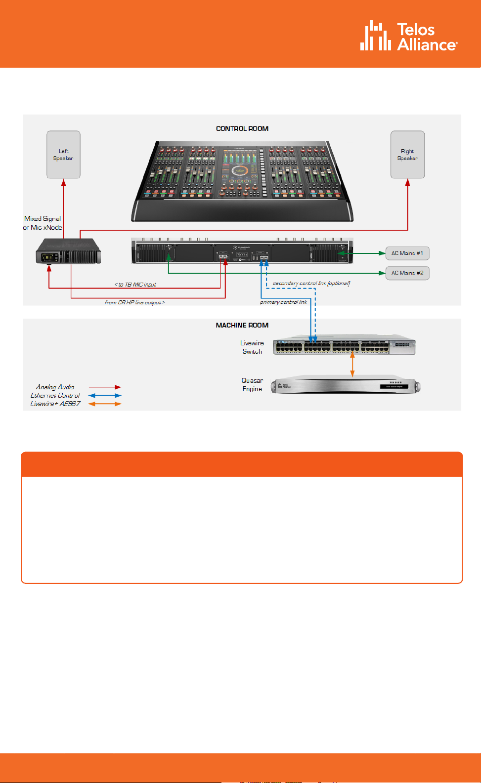
Example of simple Studio configuration.
Connection of the optional TBP-IO module is included in this drawing.
•Quasar Engine mixing engine
•Gigabit Switch configured for use on an
Axia network
•PC with access to the Axia network
ITEMS REQUIRED FOR INSTALLATION:
The following items are necessary to complete the installation and configuration.
•Quasar control surface
•Power (mains) cords
•CAT5 Ethernet cable

TelosAlliance.com
PN: 1490-00223-005 --- Quasar Quick Start Guide
QUICK START GUIDE
Steps to complete in order to get audio from the console:
1. Network Switch Configuration
2. Quasar Surface Connections
3. Quasar Surface Network Configuration
4. Quasar XR Modules discovery & configuration
5. Quasar SR Modules configuration
6. Quasar Engine Installation & network configuration
7. Checking Connection to the Quasar Engine
1. Quasar Engine Audio Outputs configuration
2. Surface Layer Configuration
3. Creating and Configuring Input Sources
4. Assigning Sources to Input Channels
5. Program Assignment & Monitoring
Network Switch Configuration
Audio over IP requires the use of an approved and properly configured switch. Not
all switches are capable of handling the trac generated by AoIP, and an improper
configuration can lead to a flood of trac on the network.
Details of switch configuration are beyond the scope of this Quick Start Guide, and it is
assumed the person responsible for installation has the necessary configuration skills or
the resources of an IT engineer.
A list of Telos Alliance-approved Ethernet switches is available on our website, at the
following url:
https://www.telosalliance.com/Axia/What-Ethernet-Switches-has-Axia-Approved
or
you may submit an online support request at the following url: https://www.telosalliance.
com/support-request.
Initial Setup
Console Configuration
TelosAlliance.com
PN: 1490-00223-005 --- Quasar Quick Start Guide
QUICK START GUIDE
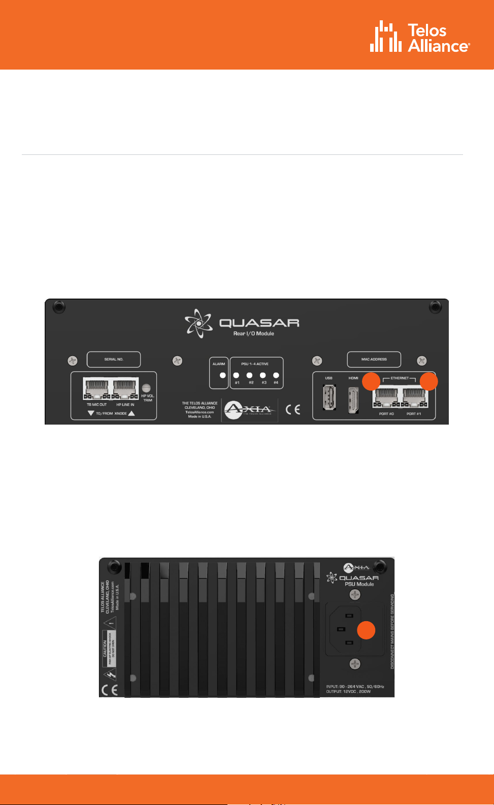
Quasar Surface Connections
Network Connections
Connect an Ethernet cable to the Primary network port (A), labeled “PORT #0” on the
console’s rear I/O board. Connect the other end of the cable to the network switch.
The Secondary network port (B), labeled “PORT #1”, can be used to create an optional
redundant network connection. Doing so will require a special configuration of the switch
ports as outlined in the Quasar Installation Guide.
A B
Mains Power Connections
Use the provided AC power cable(s) to connect the surface’s PSU module (C) to a grounded
power receptacle. If you have more than one power supply in your system, we suggest
connecting them to dierent power sources for redundancy and highly recommend the use
of a UPS (uninterruptable power supply) for each source.
C
Important - The Quasar Surface is grounded through the power
cable and therefore relies upon proper grounding of the circuit
providing power. There is no separate chassis ground.
TelosAlliance.com
PN: 1490-00223-005 --- Quasar Quick Start Guide
QUICK START GUIDE
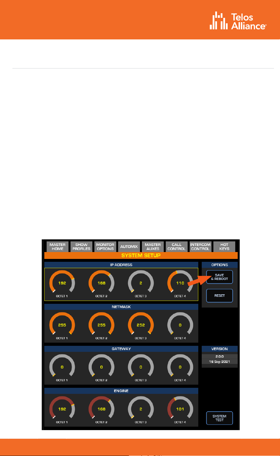
Quasar Surface Network Configuration
Quasar Surface and Quasar Engine ship with the following default IP addresses:
•Surface (Master Module) - 192.168.2.10
•Surface (XR Modules) - 192.168.2.11, 192.168.2.12, etc.
•Surface (SR Modules) – no IP address required
•Engine - 192.168.2.100
Should you need to change the default settings, or if the warning message: “No
Connection to Engine” should appear on the surface’s home screen (just above the
clock) once the system boot is completed, then you will need to enter new network
settings manually.
•Access the System Setup page on the Master Touchscreen Module, by pushing and
holding the Monitor Options key (labeled “MON OPT” and located between the two
Control Room volume pots) for 5 seconds.
•Enter the desired IP address and Netmask for the Surface and Engine using the
touchscreen or the corresponding rotary encoders beneath the display. A Gateway is
optional but typically not required when the console is part of a closed network.
•Press the “Save & Reboot” button.

TelosAlliance.com
PN: 1490-00223-005 --- Quasar Quick Start Guide
QUICK START GUIDE
Quasar XR Module Discovery & Configuration
Each fader module on the Quasar XR Surface has a unique IP address to permit
configuration via web GUI. Begin by launching a web browser and entering the IP
address of the MTS, then click on XR / ACC Modules. When prompted for authentication,
enter “user” for the user name and leave the password field blank.
All connected fader modules will be listed along with their MAC Address and IP Address.
If the pre-assigned IP addresses don’t fit into your network scheme, you can change
them here by selecting a module’s radio button, entering the new IP address, and clicking
the “Do It!” button.
Once all modules have been set, check the access to each module by entering its IP
address in your browser, or by clicking directly on each of the addresses listed in the
Console Discovery menu.
TelosAlliance.com
PN: 1490-00223-005 --- Quasar Quick Start Guide
QUICK START GUIDE
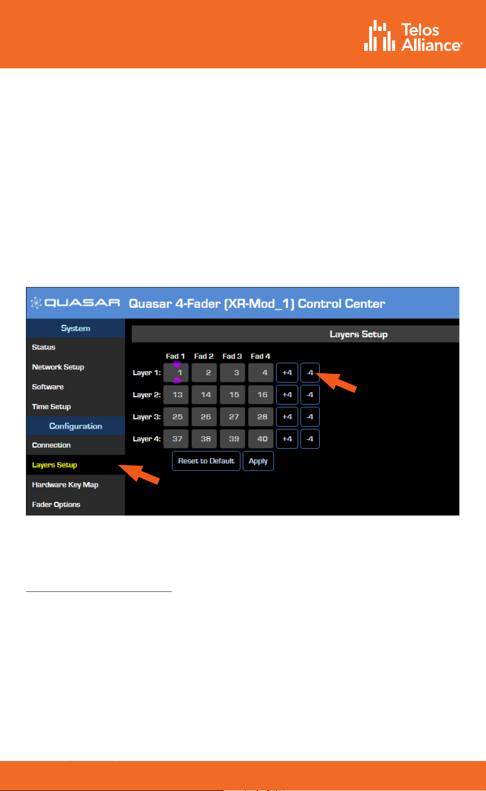
Quasar XR Surface Layer Configuration
Layers are useful when the number of DSP input channels you need to access exceeds
the number of faders or physical channel strips on your Quasar surface. Since any fader
on any module can access any input channel on the Quasar engine, you will need to
assign four input channels to each of the four available layers on every Fader Module.
•Using a PC connected to your studio network, launch a web browser and enter
the IP address assigned to the first (left-most) fader module. When prompted for
authentication, enter the user name “user” and leave the password field blank.
•In the Configuration menu, click on Layers Setup.
•Enter the desired input channel number for each layer of each of the faders. The “+4”
and “-4” buttons can quickly increment or decrement channels in groups of four.
The table shown in the figure above shows which of the 64 input channels available on
the Quasar Engine will be loaded on the four channel strips each time the LAYER 1, 2, 3, 4
buttons are pushed on the Master Module.
If you have no need for Layers, you can disable them by navigating to the Master Module
web UI and selecting the Customize link. In the Key Options section, select the “Disabled”
option from the Layers Keys Function dropdown. This will switch o the Layer buttons on
the Master module.

TelosAlliance.com
PN: 1490-00223-005 --- Quasar Quick Start Guide
QUICK START GUIDE
Quasar SR Module Configuration
Quasar SR Fader modules have no individual IP address and therefore do not need to be
discovered. They are always connected to the Master and automatically discovered. Launch
a browser and enter the IP address of the MTS module, then click on the SR Modules link.
Here you can assign Input channels of your Quasar Engine to the SR modules’ faders.
Simply type the desired Input Channel number in each of the four Fader fields for each
of the SR Modules listed in the Channel Assignment section. Then press the “Update
Assignment” button.
TelosAlliance.com
PN: 1490-00223-005 --- Quasar Quick Start Guide
QUICK START GUIDE
Quasar Engine Installation &
Network Configuration
Physical Installation
The Quasar Engine is designed to be installed in a climate-controlled environment
where any noise generated from its fans will not be an issue, such as a machine room.
Please refer to the Quasar Installation Guide for complete installation details.
Mains Power Connections
Use the provided AC power cables to connect the engine to grounded power
receptacles. We suggest connecting each supply to dierent power sources for
redundancy and highly recommend the use of a UPS (uninterruptable power supply)
for each source.
Important - The Quasar Engine is grounded through the power cable
and therefore relies upon proper grounding of the circuit providing
power. There is no separate chassis ground.
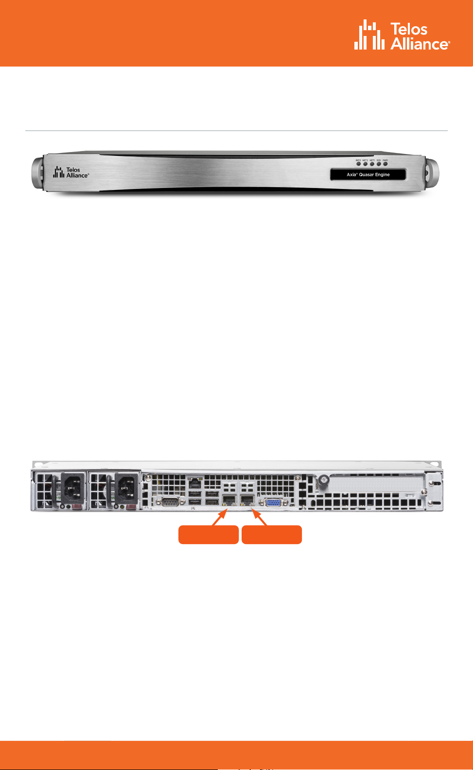
Network Connections
Connect a network cable to the NET 2 port (the right-most port when looking at the rear
panel). Connect the other end of the cable to a Gigabit port of your network switch.
Quasar Engine ships with a default IP address of 192.168.2.100 and a netmask of
255.255.255.0. This address can be changed using the web GUI once it is connected to
the network. If the IP address must be changed before connecting the Engine to the
network, follow the steps below:
•Connect a VGA monitor and a USB keyboard to the appropriate rear panel ports;
•the Basic Setup screen will be displayed.
•Select “1-LAN Settings” with the numeric keypad or up/down arrow keys,
then press Enter.
•Select “2-Configure Network Settings”, then press Enter.
•Type the new network settings with the numeric keypad, then press Enter.
•The Engine will prompt you to reboot; select “OK” to reboot with the new settings.
NET 1 NET 2
TelosAlliance.com
PN: 1490-00223-005 --- Quasar Quick Start Guide
QUICK START GUIDE
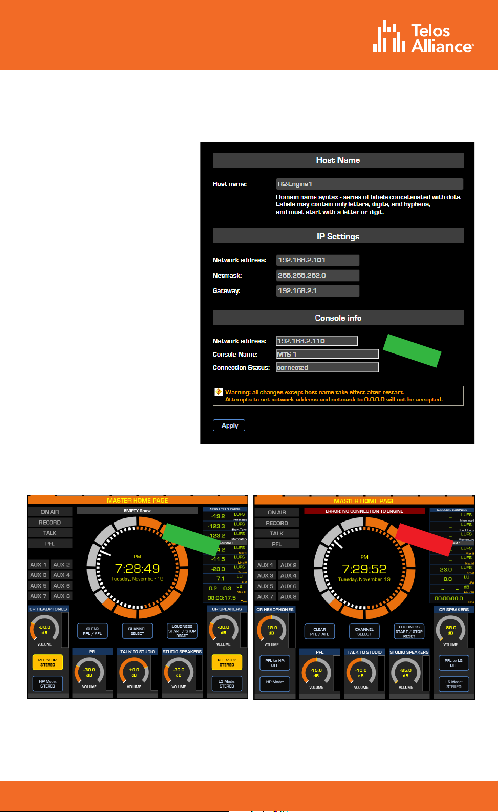
Checking the Connection to the Quasar Engine
OK!
Using a PC connected to
your studio network, launch a
web browser and enter the IP
address assigned to the Engine
into the browser’s address
bar. When prompted for
authentication enter the user
name “user”, and leave the
password field blank.
Select the Network Setup link,
then navigate to the “Console
Info” section.
Verify that the IP address of
the Quasar Master Touchscreen
(MTS) module appears and
that the connection status
shows as “Connected.”
Next, verify that there is no
error message above the clock
on the MTS home page.
The Quasar Surface is now
correctly connected to the
Quasar Engine.
OK!
NOT OK!
TelosAlliance.com
PN: 1490-00223-005 --- Quasar Quick Start Guide
QUICK START GUIDE
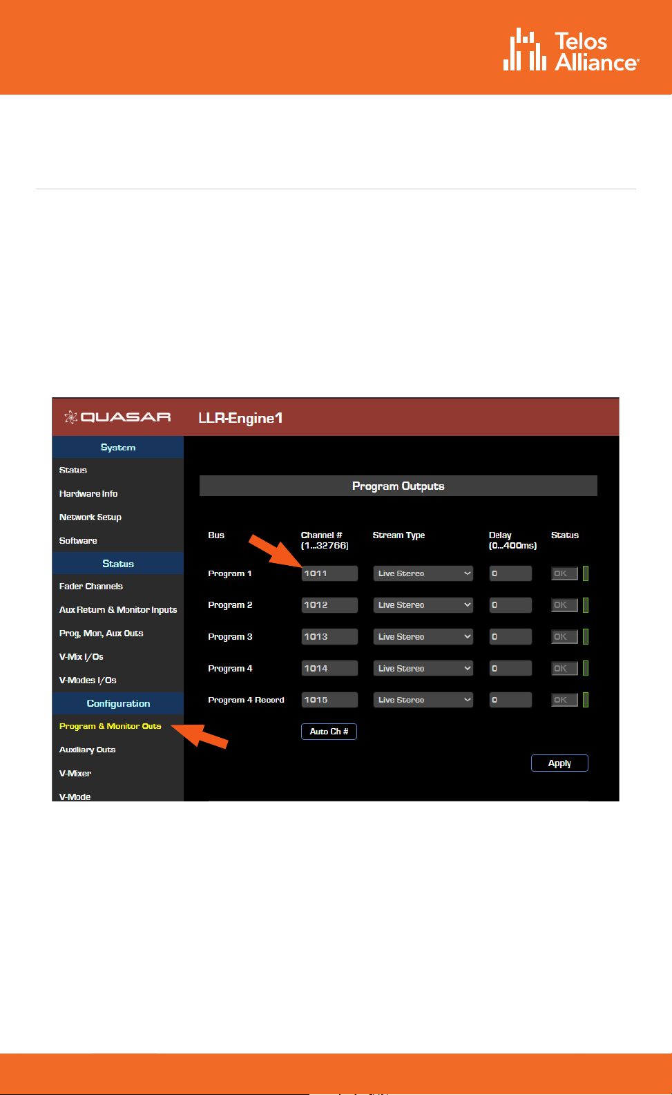
Quasar Engine Audio Outputs Configuration
Using a PC connected to your studio network, enter the IP address of the Quasar
Engine to display the web GUI.
•From the Configuration menu, select Program & Monitor Outs.
•Enter the channel numbers you planned for the Quasar Engine (Livewire Sources)
outputs.
•Enable the streams you need to be active on the Engine
•Click the “Apply” button.
Note - We recommend adopting a numbering scheme for Channel
ID’s that uses the first two or three digits of the last octet of the
Quasar Engine IP address. In the example above, the Engine has
an IP address of 192.168.2.101, and the Channel Numbers are 1011,
1012, 1013, etc. This will make it easier to identify the channels when
browsing a large network.
TelosAlliance.com
PN: 1490-00223-005 --- Quasar Quick Start Guide
QUICK START GUIDE
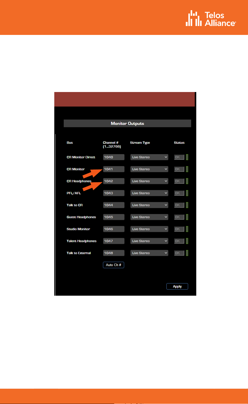
Monitor Outputs
In order to hear audio through your speakers and headphones, assign the CR Monitor
and CR Headphone streams to the Destinations (outputs) of the xNode connected to
the speakers and headphone amplifier.
TelosAlliance.com
PN: 1490-00223-005 --- Quasar Quick Start Guide
QUICK START GUIDE
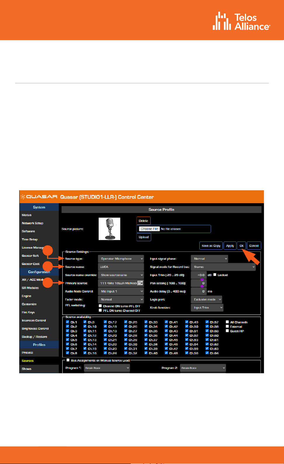
Creating and Configuring Input Sources
In order for sources to appear as Channel inputs on the Quasar Surface, they must first
be created and a source type specified.
•Using a PC connected to your studio network, enter the IP address of the Quasar
Surface to display the web GUI.
•Navigate to the Profiles menu, then to Sources. Click “Create New Source Profile”.
•Select the Source Type (A). Enter the Source Name (B).
•Click the Browse button to the right of the Primary Source field and select the
desired source from the list. Click “OK”.
•Repeat these steps for additional sources which will then appear in the Channel
Input > Sources menu of your Quasar Surface.
For more detailed information on how to create and configure all your Network
sources, please refer to the Quasar User manual.
A
B
C
TelosAlliance.com
PN: 1490-00223-005 --- Quasar Quick Start Guide
QUICK START GUIDE
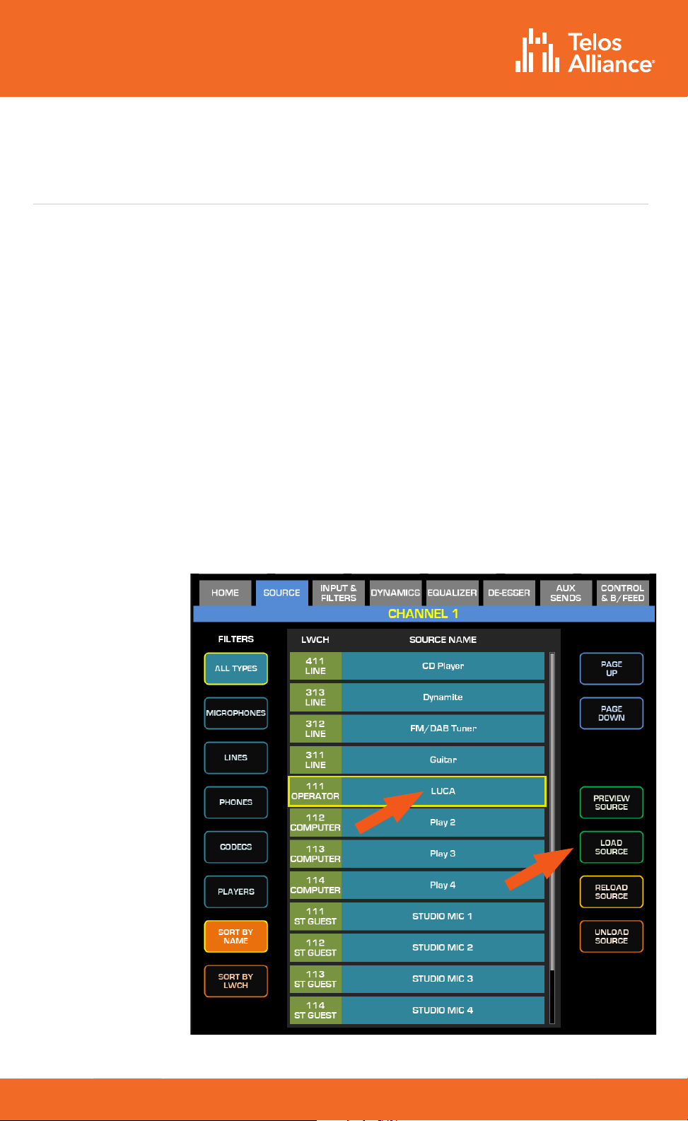
Assigning Sources to Input Channels
Once Sources have been created, they must be assigned to input channels on the
Quasar Engine and then saved to a Show Profile.
Show Profiles can be created in one of two ways:
•Sources can be assigned directly from the console and the resulting configuration
captured as a Show.
•A Show Profile can be created from the web GUI by assigning sources to channels.
Creating a Show Profile From The Console
•Push the top encoder of the channel strip to which you want to assign a source,
then select the “Source” tab in the Master Touchscreen module.
•All configured and available sources on the network will appear; it may be necessary
to use the touchscreen to scroll down to show more sources.
•Push the “Load Source” button.
Note - inactive
sources – those
generated by
devices which
are not con-
nected to the
network, or
switched o
– will not be
detected by
the Quasar and
therefore will
not show up on
the above list.

TelosAlliance.com
PN: 1490-00223-005 --- Quasar Quick Start Guide
QUICK START GUIDE
Creating a Show Profile From The Console
•Using a PC connected to your studio network, enter the IP address of the Quasar
Surface to display the web GUI.
•Navigate to the Profiles menu, then to the Shows menu.
•Click on the “Create new show profile” button.
•Enter a name for the new Profile and confirm.
A new Show Profile configuration page will appear where Sources can be assigned to
input channels from a dropdown menu.
TelosAlliance.com
PN: 1490-00223-005 --- Quasar Quick Start Guide
QUICK START GUIDE
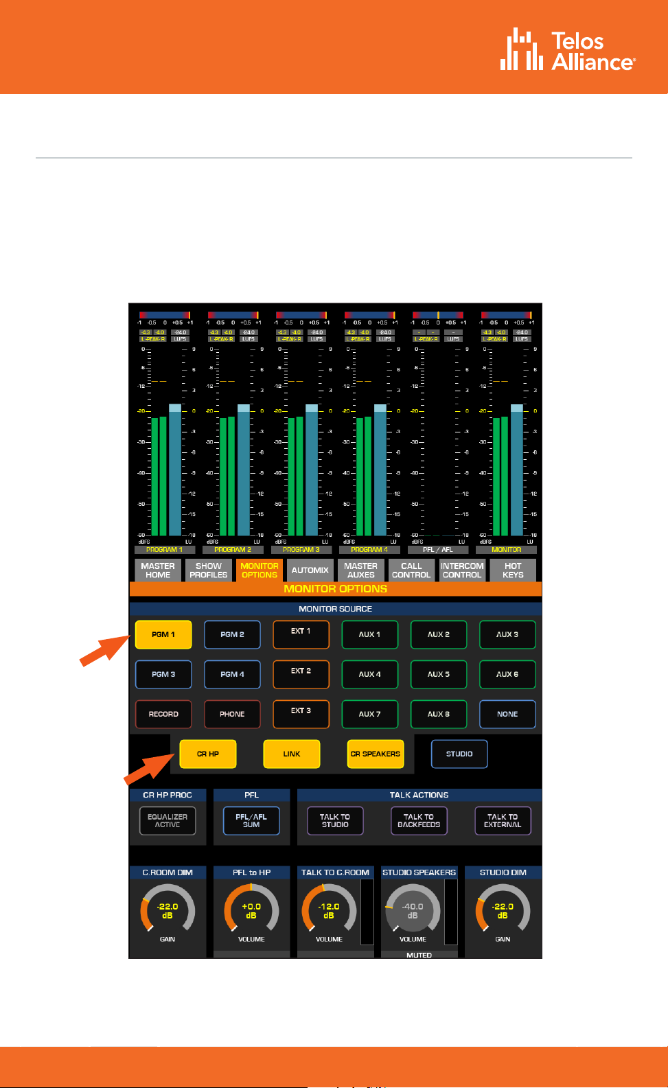
Program Assignment and Monitoring
The output of each fader strip must be assigned to a Program output.
•Press one of the PGM keys on the fader strip; it will illuminate to indicate that it
has been assigned.
•Press the On key at the bottom of the fader strip and move the fader up.
•Your meters should be active as shown below.
To hear the audio, make sure you have selected the same Program assigned above
as source to your CR Headphones or Speakers, using the controls on your Monitor
module, and that the volume is set at an appropriate level.

TelosAlliance.com
PN: 1490-00223-005 --- Quasar Quick Start Guide
QUICK START GUIDE
INFORMATION ABOUT YOUR NEW PRODUCT
IMPORTANT!
Telos Alliance strongly suggests that you use an Uninterruptible Power Supply (UPS)
with power line filtering to prevent damage to the unit during electrical storms and
power surges. Please note that damage due to lightning is not covered under the
product Warranty (refer to your User Manual for warranty information).
For more information on lightning protection please visit our website:
http://blogs.telosalliance.com/tech/surge-suppression-pointers

TelosAlliance.com
PN: 1490-00223-005 --- Quasar Quick Start Guide
QUICK START GUIDE
This page intentionally blank

TelosAlliance.com
PN: 1490-00223-005 --- Quasar Quick Start Guide
QUICK START GUIDE
This page intentionally blank

TelosAlliance.com
PN: 1490-00223-005 --- Quasar Quick Start Guide
QUICK START GUIDE
1241 Superior Ave. • Cleveland, Ohio, 44114, USA • +1.216.241.7225 • TelosAlliance.com
© 2021 Telos Alliance®. All Rights Reserved. C21/7/16083. P/N 1490-00223-005 QUASAR QUICK START GUIDE
Subscribe to our Newsletter
Weekly updates on all things broadcast via email
TelosAlliance.com/newsletter
Social Media
Facebook: /TelosAlliance
Twitter: @TelosAlliance
LinkedIn: /TelosAlliance
YouTube: TelosAllianceTV
Product Catalog
TelosAlliance.com/catalog
24/7 Tech Support
Radio: +1 (216) 622-0247
TV: +1 (717) 735-3611
Radio: support@telosalliance.com
TV: support@linearacoustic.com
Quick Links
Other manuals for Axia QUASAR XR
2
This manual suits for next models
1
Table of contents
Other Telos Alliance Music Mixer manuals


