Teltronics SEB NET-PATH Operating instructions

SEB®
NET-PATH™
Installation and Operation Guide


SEB®
NET-PATH™
Installation and Operation Guide

SEB NET-PATH Installation and Operation Guide
This document is the copyright of Teltronics, Inc. and is intended for exclusive use of Teltronics
customers. All rights are reserved. Information in this document is subject to change without notice.
Companies, names, and data used in examples herein are fictitious unless otherwise noted. No part of
this document may be reproduced or transmitted in any form or by any means, electronic or mechanical,
for any purpose, without the express written permission of Teltronics, Inc.
© 2006-2007 Teltronics, Inc. All rights reserved.
The material in this document has been carefully reviewed; however, Teltronics, Inc. does not guarantee
it to be free of all errors or omissions and reserves the right to make corrections, changes, updates, or
revisions to the information contained herein.
SEB and NET-PATH are trademarks of Teltronics, Inc.
Other than those held by Teltronics, Inc., any other brand and product names referenced in this manual
are trademarks or registered trademarks of their respective holders and are used here for informational
purposes only.
Teltronics, Inc.
2150 Whitfield Industrial Way
Sarasota, Florida 34243-4046 USA
Visit our web site at www.teltronics.com
Part Number: 610-0000-0434 Rev. H (Jan/07)

Revision History
01/07 - Revision H
• Update to Battery section (Chapt. 2).
04/06 - Revision G
• Updated DC input description (Chapts. 1 & 2).
09/05 - Revision F
• Updated the Script command line interface command with the “ScriptParm” option (Chapt. 3).
07/05 - Revision E
• Added “Table 4-2: Country Code Definitions for Modem Type 239.”
06/05 - Revision D
• Updated “Table 3-1: NET-PATH Commands” with RLOGINIP, RLOGINHOST, and XPARA
commands.
04/05 - Revision C
• Added “Jumper Connections” (Chapter 5).
02/05 - Revision B
• Updated “Table 2-3: Contact Sensor Strap Options.”
02/05 - Revision A
• First release.


i
Table of Contents
Preface
Description and Specifications
Introduction ...................................................................................................... 1-1
Determining the NET-PATH Model ................................................................ 1-1
NET-PATH Model Structure ............................................................................1-1
Description ........................................................................................................1-2
Hardware Features ............................................................................................1-3
Hardware Specifications ...................................................................................1-4
Installation
Site Requirements ............................................................................................. 2-1
Unpacking .........................................................................................................2-1
Rack Mount Instructions ..................................................................................2-2
Connections ..................................................................................................... 2-3
RS232C Connections ........................................................................................2-4
Telephone Line Connection ............................................................................2-5
Contact Sensor Inputs .......................................................................................2-5
Contact Sensor Wiring ...................................................................................... 2-5
Dry Contact Applications ................................................................................. 2-6
Wet Contact Application RS232C .................................................................... 2-6
Wet Contact Application RS423A ...................................................................2-7
Contact Sensor Strap Options ...........................................................................2-8
Contact Sensor Wiring Tables ........................................................................ 2-10
Output Relays .................................................................................................2-11
Output Relay Specifications ....................................................................2-12
Output Relays Internal Wiring Table ...................................................... 2-12
Voltage Sensor ................................................................................................2-12
DC Voltage Sensor Internal Wiring Table .............................................. 2-12
Temperature Sensor ........................................................................................2-13
Internal Temperature Sensor ...................................................................2-13
External Temperature Sensor .................................................................. 2-13
Temperature Sensor Internal Wiring Table .............................................2-14
Power .............................................................................................................. 2-15
Reset Button ...................................................................................................2-15
Battery ............................................................................................................2-15
Power-Up and Verification ............................................................................. 2-16
Internal Battery Test ....................................................................................... 2-16
Functional Verification ................................................................................... 2-16
NET-PATH Test, Incoming ....................................................................2-17
Transparency to Host ............................................................................... 2-17
NET-PATH Test Outgoing ...................................................................... 2-17
Storage/Relocation ..................................................................................2-17

Table of Contents
ii
Operation
General ............................................................................................................. 3-1
Interactive Command Mode ............................................................................. 3-2
Connecting to the NET-PATH Serial Port ....................................................... 3-2
Connecting to the NET-PATH via Modem ..................................................... 3-3
Connecting to the NET-PATH via the Network .............................................. 3-3
Using the Remote Agent Manager to Establish a Dial-Up Connection ........... 3-3
Using the Remote Agent Manager to Establish a Network Connection .......... 3-4
Useful Command Line Interface Commands ................................................... 3-5
Indicators and Diagnostics
Front Panel Indicators ..................................................................................... 4-1
Console Connector ........................................................................................... 4-1
Indicators .......................................................................................................... 4-1
LCD Display .................................................................................................... 4-2
Display Content ................................................................................................ 4-2
Boot Sequence .................................................................................................. 4-2
Main Log-in Screen .......................................................................................... 4-3
Login Procedure ............................................................................................... 4-3
Navigation ........................................................................................................ 4-3
Menu Options ................................................................................................... 4-4
Event Viewer .................................................................................................... 4-4
Devices Menu Option ....................................................................................... 4-4
Alarm LED ................................................................................................ 4-4
Battery ....................................................................................................... 4-5
Buzzer ....................................................................................................... 4-5
Contact Sensors ......................................................................................... 4-5
DC Voltage ............................................................................................... 4-5
Modems ..................................................................................................... 4-5
Relays ...................................................................................................... 4-10
Serial Ports .............................................................................................. 4-10
Temp Sensors .......................................................................................... 4-10
Shutdown ................................................................................................ 4-10
System Reset Button ...................................................................................... 4-11
Tests ............................................................................................................... 4-11
Troubleshooting ............................................................................................. 4-11
Troubleshooting Incoming Calls ............................................................. 4-11
Troubleshooting Outgoing Calls ............................................................. 4-12
Serviceable Components
General ............................................................................................................. 5-1
UPS Battery ...................................................................................................... 5-1
UPS Battery Replacement Procedure ............................................................... 5-2
Coin Cell Battery .............................................................................................. 5-3
Jumper Connections ......................................................................................... 5-4
Index

iii
Warning This equipment has been tested and found to comply with the limits for a Class A
digital device pursuant to Part 15 of FCC rules. These limits are designed to provide
reasonable protection against harmful interference when this equipment is operated in
a commercial environment. This equipment generates, uses, and can emit radio
frequency energy and, if not installed and used in accordance with the instruction
manual, may cause harmful interference to radio communications. Operation of this
equipment in a residential area is likely to cause harmful interference in which case
the user will be required to correct the interference at his/her own expense.
Caution • Never install telephone wiring during a lightning storm.
• Never install telephone jacks in wet locations unless the jack is specifically
designed for wet locations.
• Never touch telephone wires or terminals that are not insulated unless the tele-
phone line is disconnected at the network interface.
• Use caution when installing or modifying telephone lines.
FCC Notice FCC Requirements for Consumer Products
The Federal Communications Commission (FCC) has established Rules which permit
this device to be directly connected to the telephone network. This equipment
complies with FCC Part 68 and TIA 968. Standardized jacks are used for these
connections. This equipment should not be used on party lines or coin lines.
If this device is malfunctioning, it may also be causing harm to the telephone
network; this device should be disconnected until the source of the problem can be
determined and until repair has been made. If this is not done, the telephone company
may temporarily disconnect service.
The telephone company may make changes in its technical operations and
procedures: if such changes affect the compatibility or use of this device, the
telephone company is required to give adequate notice of the changes.
If the telephone company requests information on what equipment is connected to
their lines, inform them of:
a) The telephone number that this unit is connected to
b) The ringer equivalence number
c) The USOC jack required [RJ-11-C], and
d) The FCC Registration Number
Items (b) and (d) are indicated on the label. The ringer equivalence number (REN)
determines how many devices can be connected to your telephone line. In most areas,

Notices
iv
the sum of the RENs of all devices on any one line should not exceed five (5.0). If too
many devices are attached, they may not ring properly.
An FCC compliant telephone cord and modular plug is provided with this equipment.
This equipment is designed to be connected to the telephone network or premises
wiring using a compatible modular jack, which is Part 68 compliant. See installation
instructions for details.
The Telephone Consumer Protection Act of 1991 makes it unlawful for any person to
use a computer or other electronic device, including fax machines, to send any
message unless such message clearly contains in a margin at the top or bottom of each
transmitted page or on the first page of the transmission, the date and time it is sent
and an identification of the business or other entity, or other individual sending the
message and the telephone number of the sending machine or such business, other
entity, or individual. (The telephone number provided may not be a 900 number or
any other number for which charges exceed local or long-distance transmission
charges.)
Service Requirements
In the event of equipment malfunction, all repairs should be performed by our
Company or an authorized agent. It is the responsibility of users requiring service to
reportthe need for service to our Company or to one of our authorized agents. Service
can be facilitated through our office at:
Teltronics Incorporated
2150 Whitfield Industrial Way
Sarasota, FL 34243-4046
TEL: (941) 753-5000
Canadian
Notice Canadian Department of Communications Requirements
• This equipment meets CS-03 Requirements for Terminal Equipment and Certi-
fied Protection Circuitry of the Canadian Department of Communications, meet-
ing telecommunications requirements for safety, operation, and telephone
network protection. The Department does not guarantee satisfactory equipment
operation.
• Before installing this equipment:
• Be sure your local telecommunications company allows you to connect your
equipment to its lines.
• Use approved connectors. Most companies prohibit using customer-supplied
jacks. If using a single line, you may be able to use a telephone extension cord.
• Electrical ground connections for the power utility lines, telephone lines, and
internal metallic water pipes are connected together, particularly in rural areas.
DO NOT ATTEMPT TO MAKE GROUND CONNECTIONS YOURSELF.
Contact the appropriate electrical inspection authority or electrician.
• Any equipment malfunctions, or repairs or alterations you make to this equip-
ment, may cause the telecommunications company to ask you to disconnect the
equipment. All repairs to this equipment should be made by an authorized Cana-
dian maintenance facility designated by the suppliers.
• Compliance with the above conditions may not prevent degradation of service in
some situations.

NET-PATH Installation and Operation Guide
v
The Canadian Department of Communications requires notification of the following:
• Equipment Manufacturer: Teltronics, Inc.
• Equipment Load Number: SEBea – 9
• Connecting arrangement code: CA11A
The load number (LN) assigned to each terminal device denotes the ratio of its load to
the total load connected to a telephone loop. The load number is used by the device to
prevent overloading. The termination on a loop may consist of any combination of
devices, subject only to the requirement that the load number total for all the devices
does not exceed 100.
This digital apparatus does not exceed the Class A limits for radio noise emissions
from digital apparatus set out in the Radio Interference Regulations of the Canadian
Department of Communications.
Le présent appareil numérique n'émet pas de bruits radioélectriques dépassent les
limites applicables aux appareils numérique de la class A prescrites dans le Réglement
sur le brouillage radioélectrique édicté par le ministére des Communications du
Canada.
Professional installation only, no user-serviceable parts inside except as indicated in
this installation guide.
Important Safety Instructions
When using your telephone equipment, basic safety precautions should always be
followed to reduce the risk of fire, electric shock and injury to persons, including the
following:
• Do not use this product near water, for example, near a bath tub, wash bowl,
kitchen sink or laundry tub, in a wet basement or near a swimming pool.
• Avoid using a telephone (other than a cordless type) during an electrical storm.
There may be a remote risk of electric shock from lightning
• Do not use the telephone to report a gas leak in the vicinity of the leak.
• Use only the power cord and batteries indicated in this manual. Do not dispose of
batteries in a fire. They may explode. Check with local codes for possible special
disposal instructions.
Warning Danger of explosion if battery is incorrectly
replaced. Replace only with the same or equivalent type
recommended by the manufacturer. Dispose of used
batteries according to the manufacturer's instructions.”

Notices
vi
Save These Instructions
Importantes Mesures De Sécurité
• Certaines mesures de sécurité doivent être prises pendant l'utilisation de matérial
téléphonique afin de réduire les risques d'incendie, de choc électrique et de
blessures. En voici quelquesunes:
• Ne pas utiliser l'appareil près de l'eau, p. ex., près d'une baignoire, d'un lavabo,
d'un évier de cuisine, d'un bac à laver, dans un sous- sol humide ou près d'une
piscine.
• Éviter d'utiliser le téléphone (sauf s'il s'agit d'un appareil sans fil) pendant un
orage électrique. Ceci peut présenter un risque de choc électrique causé par la
foudre.
• Ne pas utiliser l'appareil téléphonique pour signaler une fuite de gaz s'il est situé
près de la fuite.
• Utiliser seulement le cordon d'alimentation et le type de piles indiqués dans ce
manuel. Ne pas jeter les piles dans le feu: elles peuvent exploser. Se conformer
aux règlements pertinents quant à l'élimination des piles.
Conserver Ces Instructions
Communication
Certification
Laboratory
This product has been safety tested and found compliant to USA safety standards.
SEBea is certified the UL 60950 safety standard for Information Technology
Equipment. This ensures safe operation in the office business environment.

NET-PATH Installation and Operation Guide
vii
European
Community
Related
Requirements
Warning
This is a Class A Product. In a domestic environment this product may cause radio
interference in which case the user may be required to take adequate measures.”
This equipment has been tested and is compliant with the EMC and Low Voltage
directives of the European Community. A system with the CE marking meets or
exceeds the following technical standards:
• EN 55022 "Limits and methods of measurement of radio interference characteris-
tics of information technology equipment"
• EN 50024-1 "Information technology equipment - Immunity characteristics -
Limits and methods of measurement”
• EN 60950 "Safety of information technology equipment, including electrical busi-
ness equipment"
• In addition to the above standards, this system has also met the requirements of
the following European standards:
• EN 61000-3-2 "Disturbances in supply systems caused by household appliances
and similar electrical equipment Part 2: Harmonics"
• EN 61000-3-3 "Disturbances in supply systems caused by household appliances
and similar electrical equipment Part 3: Voltage fluctuations"

Notices
viii
International
Modem
Operation
Using the SEBea in Austria, Belgium, Germany, Spain and Switzerland
Teltronics is required to provide the following information as a condition of the
telecommunications conformity to Common Technical Regulation 21 (CTR 21/TBR
21). You may also be responsible for meeting requirements other than those outlined
in this document. This SEBea product requires an RJ11 adapter to be installed on
any line that receives Metering Pulses. Metering pulses are used for billing
purposes and are normally not present unless requested by the subscriber. The
subscriber may request the Network Provider to add or remove Metering Pulse
service. Metering pulses are present on all lines in Switzerland.
TeleAdapt Part number TLFTR (www.TeleAdapt.com) is the metering pulse filter
recommended by Teltronics.
Using the SEBea in Norway & Spain
This product complies with all of the standard DC voltage requirements as specified
in the EU standards document CTR 21/TBR 21. However, the SEBea does not meet
the more unusual requirements for maximum voltage in the loop state, as specified in
specification EG 201 121 V1.1.1 advisory note NO 02 for Norway and Advisory note
ES 01 for Spain. In the unlikely event of low loop current, the DC voltage may exceed
the 7.4 V maximum. If this occurs, the user may experience problems with the
Central Office recognizing an off-hook condition. This condition could occur in the
event that the subscriber is at the end of very long telephone lines, which are attached
to older Central Office equipment.
Modem Configuration Restrictions
The modem used in this product is configured to meet specific country requirements.
This configuration is in the form of AT command settings sent to the modem prior to
installation. Changing settings may cause a modem to become non-compliant with
national telecom requirements in specific countries.
SEBea factory settings configure the modem for use in North America. If you are
installing the SEBea in a different country, do not connect the modem to the telephone
interface until the proper country code is entered though the user interface switches
on the LCD front panel.

NET-PATH Installation and Operation Guide
ix
Declaration of Conformity
We, Teltronics, Inc. located at 2150 Whitfield Industrial Way, Sarasota, Florida, USA
34234 declare under our sole responsibility that the SEBea product to which this
declaration relates is in conformity with the following standards and / or other
normative documents:
Low Voltage Directive 73/23/EEC
• IEC 609050 3rd Edition
• IECEE CB-Scheme US/781/ITS
EMC Directive 89/336/EEC
• EN55022 Class A
• EN55024-98
• EN61000-3-2
• EN61000-3-3
• EN60950
R&TTE Directive 1999/5/EC
• CTR 21/TBR 21
The technical documentation relevant to the above equipment will be held at:
Teltronics LTD
The Sun
27 Weston Rd.
Olney
Buckinghamshire
UK
Warranty and
Repair Warranty Statement. Teltronics warrants its products are free from defects in
material and workmanship for a period of one year from the shipping date. Teltronics
tracks serial numbers for its products. Teltronics can use the serial number to
determine the shipping date.
Return for Repair. Customers can return to Teltronics,at customer's risk and expense,
any Teltronics product that fails in normal service during the warranty period. The
failed product will be repaired or replaced at the option of Teltronics and returned to
the customer at Teltronics’ risk and expense. Correction of defects by repair or
replacement shall constitute the fulfillment of all obligations of Teltronics with respect
to any product sold.
This warranty shall be void for any product that was subjected to (1) alteration or
repair by persons not authorized by Teltronics, (2) misuse by negligence or accident,
(3) operation beyond the design range, or (4) improper test or mishandling in any way.
Products sold by Teltronics but manufactured by others, such as, but not limited to,
tape drives, printers, and CRT terminals, carry the warranty of the manufacturer.
Diskettes are warranted for a period of sixty days from date of shipment. Additionally,
Teltronics shall only be required to provide replacement or repair software whose
purpose is to correct defects not disclosed inthe Teltronics System Difficulties Product
Bulletin in effect at the time of sale by Teltronics.

Notices
x
The warranty of repair or replacement at Teltronics' facility contained herein shall be
the exclusive remedy for breach of warranty and shall be in lieu of and excludes all
other express or implied warranties of merchandise, fitness, or otherwise.
Teltronics shall not be liable for any special or consequential damages or for loss,
damage or expense arising from delays in delivery, use of the equipment or arising
from the inability to use the equipment with any other equipment or from any other
cause.
Spare Parts. Teltronics recommends that spare parts be maintained by those
responsible for sustaining end-user, Teltronics equipment. Recommendations for
spare parts inventory can be obtained from Teltronics upon request.
Spare parts for emergencies can be obtained from Teltronics, when available, at the
customer’s expense. Such spare parts will be new or reconditioned parts and will
carry a new parts warranty of ninety days from the shipping date.
Return Authorization. A return authorization number must accompany all
equipment returned to Teltronics for repair or replacement. This number is obtained
by telephone from the Customer Repair Department of Teltronics. This number shall
be used for all paperwork or telephone transactions between the customer and
Teltronics and shall be included in the shipment of the returned equipment and clearly
marked on the outside of shipping containers.
A description of the mode of failure or exhibited trouble symptoms shall also
accompany the equipment in order to assist Teltronics in better serving the customer's
needs.
When equipment returned for repair is found to be free of defects, the customer will
be billed in accordance with the then-current out-of-warranty repair charges.
Design Changes. Teltronics reserves the right to make any changes in design or
construction of its products at any time without incurring the obligation to make any
change whatsoever to products previously shipped.

xi
Preface
This manual provides instructions for installing, verifying, and troubleshooting the
NET-PATH remote agent device.
The NET-PATH is a highly flexible, solid-state data-collection and events-reporting
device that you can use with a wide variety of applications. The NET-PATH is a
critical component of a larger system that usually consists of a computer, application
software, and one or more NET-PATH units. While this manual does not cover
specific applications, it does cover how to properly install and check a NET-PATH.
Before you can use the NET-PATH, you must program it with the necessary options
and parameters. This involves downloading a database to the NET-PATH. A detailed
discussion of the database and its interaction with the NET-PATH is beyond the scope
of this manual. This manual only covers the database to that point necessary for the
installer to ensure the NET-PATH functions properly.
This manual consists of the following sections:
Physical Description And Specifications: Details the specifications and
requirements of the NET-PATH.
Installation: Lists therequirements for installation, connector pindesignations, and a
procedure for verifying the proper functions of the NET-PATH.
Operation: Includes instructions for accessing the NET-PATH Interactive and
Transparent modes. It also includes a description of the NET-PATH function when
events occur, and steps users can follow to retrieve information.
Indicators and Diagnostics: Describes the front panel indicators and their meaning.
It also describes possible causes and actions necessary to rectify improper operations.
Serviceable Components: Lists the NET-PATH components that can be upgraded or
replaced and includes their service procedures.
Index: Locates the first, major usage of important terms.

Preface
xii
Notes

Page 1-1
1
Description and Specifications
Introduction NET-PATH is available in several configurations. All standard models include:
• 8 serial ports, 1 NIC
• 1 56K BPS modem
• 16 contact sensors
• 2 output relays (available through RJ45 connector)
• 1 DC voltage sensor (requires optional external cable)
• 2 temperature sensors, one internal, one external (external sensor requires addi-
tional equipment)
•integratedUPS
• LCD display panel
• audible alarm
• basic event processing software including Python script execution
Configuration variables include four RS232 ports, eight contact sensors, and SNMP
Segment Management software, AC or DC input power.
Determining the
NET-PATH
Model
The serial number and model information is on a label attached to the bottom of the
unit.
NET-PATH
Model Structure Figure 1-1 shows how to use the model number to determine basic hardware
functions. The figure shows model 43308-U2OSA, which includes four serial ports, a
North American modem, 20 MB of memory, and networking with management for
twenty network elements.

Description and Specifications
Page 1-2
Figure 1-1 NET-PATH Model Number Format
All basic units have four or eight host ports. Technicians can use one of these ports as
a dedicated local port, or as a standard host port.
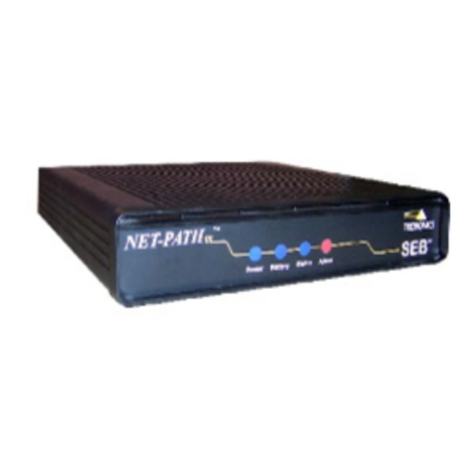
Description The NET-PATH is housed in an aluminum case as shown in the following figure.
Figure 1-2 NET-PATH
Connections for commercial power, the host systems, external sensors, terminal, and
the telephone line are on the back of the unit. See “Connections” on page 2-3. The
LED status indicators on the front indicate the power status, battery charge status,
application or database validity, and alarm conditions. See “Console Connector” on
page 4-1.
Table of contents
Other Teltronics Switch manuals
