TELUS iR1200 User manual

iR1200 Rugged Modem
iR1200 GPS-EnabledModem
INSTALLATION GUIDE


TABLE OF CONTENTS
TABLE OF FIGURES........................................................................................................................................................................................................1
FCC COMPLIANCE..........................................................................................................................................................................................................2
INTRODUCTION...............................................................................................................................................................................................................3
BoxContents........................................................................................................................................................................3
DocumentsAvailableOnline.............................................................................................................................................3
RequiredComponentsforInstallation(soldseparately)..........................................................................................................3
Componentsfor Mobile Environment (soldseparately)......................................................................................................3
ComponentsforFixedEnvironment (soldseparately)........................................................................................................4
HowtoOrderRequiredComponents.................................................................................................................................4
RequiredComponentsforOperation.....................................................................................................................................4
iDENPacket DataApplet...............................................................................................................................................4
DataAccountActivation...................................................................................................................................................4
CustomerCare......................................................................................................................................................................4
OVERVIEW.........................................................................................................................................................................................................................5
GeneralOverview.................................................................................................................................................................5
ModemOperatingModes.....................................................................................................................................................5
ModemConfigurations.........................................................................................................................................................5
iR1200RuggedModem.....................................................................................................................................................6
iR1200GPS-EnabledModem............................................................................................................................................6
ModemSpecifications..........................................................................................................................................................6
INSTALLATION PREPARATION.................................................................................................................................................................................8
Before YouStart Installing...................................................................................................................................................8
InstallationPlanning.............................................................................................................................................................8
PlanningModemLocation................................................................................................................................................8
ModemDimensions......................................................................................................................................................8
PlanningAntennaLocation...............................................................................................................................................9
PlanningCableLayout....................................................................................................................................................10
Serial CableRouting...................................................................................................................................................10
InstallationTools............................................................................................................................................................10
MOBILE INSTALLATION.............................................................................................................................................................................................11
InstallationSteps................................................................................................................................................................11
MountingtheModem.........................................................................................................................................................11
SelectModemLocation...................................................................................................................................................11
MounttheModem...........................................................................................................................................................12
MountingtheAntenna(s)....................................................................................................................................................12
ApprovedAntennas.........................................................................................................................................................12
Select AntennaLocation..................................................................................................................................................12
MounttheAntenna(s)......................................................................................................................................................13
MountModemAntenna...............................................................................................................................................13
MountGPS Antenna (optional)....................................................................................................................................13
RouteandConnect Cables..................................................................................................................................................13
ApprovedCable..............................................................................................................................................................13
RouteandConnect PowerCable.....................................................................................................................................14
RouteandConnectIgnitionCable...................................................................................................................................15

TELUS Mobility™
RouteandConnect AntennaCable(s)...............................................................................................................................15
RouteandConnect DataCable(s)....................................................................................................................................15
OtherMobileInstallation Configurations.............................................................................................................................15
ContinuousPowerConfiguration....................................................................................................................................15
MountingtheModem..................................................................................................................................................16
MountingtheAntenna(s).............................................................................................................................................16
RouteandConnect PowerCable..................................................................................................................................16
RouteandConnect IgnitionCable................................................................................................................................16
RouteandConnect AntennaCable(s)...........................................................................................................................16
RouteandConnect DataCable(s)................................................................................................................................17
ConfigurationforDockingStation...................................................................................................................................17
MountingtheModem..................................................................................................................................................17
MountingtheAntenna(s).............................................................................................................................................17
RouteandConnect PowerCable..................................................................................................................................17
RouteandConnect IgnitionCable................................................................................................................................17
RouteandConnect AntennaCable(s)...........................................................................................................................18
RouteandConnect DataCable(s)................................................................................................................................18
FIXED INSTALLATION.................................................................................................................................................................................................19
InstallationSteps................................................................................................................................................................19
MountingtheModem.........................................................................................................................................................19
SelectModemLocation...................................................................................................................................................19
MounttheModem...........................................................................................................................................................19
MountingtheAntenna(s)....................................................................................................................................................20
ApprovedAntennas.........................................................................................................................................................20
Select AntennaLocation..................................................................................................................................................20
MounttheAntenna(s)......................................................................................................................................................20
MountModemAntenna...............................................................................................................................................20
MountGPS Antenna (optional)....................................................................................................................................21
RouteandConnect Cables..................................................................................................................................................21
ApprovedCables.............................................................................................................................................................21
RouteandConnect PowerCable.....................................................................................................................................21
RouteandConnect AntennaCable(s)...............................................................................................................................22
RouteandConnect DataCable(s)....................................................................................................................................22
VERIFYINGINSTALLATION......................................................................................................................................................................................23
PoweringUptheModem....................................................................................................................................................23
Powering Up–MobileInstallation..................................................................................................................................23
Powering Up–FixedInstallation....................................................................................................................................23
CommunicationIndicators..................................................................................................................................................24
Packet Data....................................................................................................................................................................24
CircuitSwitched Data.....................................................................................................................................................24
TROUBLESHOOTING....................................................................................................................................................................................................25
CommonProblems.............................................................................................................................................................25
DiagnosticPort...................................................................................................................................................................26
HyperTerminal Setup..........................................................................................................................................................26
Diagnostic Menu................................................................................................................................................................28

UnsolicitedFirmwareUpdates............................................................................................................................................29
SAFETYNOTICE.............................................................................................................................................................................................................30
Safeand EfficientOperationGuidelines..............................................................................................................................30
Exposure toRadioFrequencyEnergy..................................................................................................................................30
MedicalandPersonalElectronicDevices............................................................................................................................30
Pacemakers....................................................................................................................................................................30
HearingAids..................................................................................................................................................................30
OtherMedicalDevices....................................................................................................................................................30
Interference withOtherElectronicDevices..........................................................................................................................30
INDEX.................................................................................................................................................................................................................................31
IMPORTANT!
PleasereadSafetyNoticeonpage30beforeusing themodem.
Last Updated
RFM-4200-5015 Rev1
JULY2004
©2004TELUSMobilityandtheTELUSMobilitylogoareregistered trademarksof TELUSCorporation.


iR1200Modem
www.telusmobility.com 1
TABLE OF FIGURES
TableofFigures Page
Figure1-iR1200GPS-Enabled Modem................................................................................................................................5
Figure2-Rear PanelofiR1200Rugged Modem...................................................................................................................6
Figure3-Rear PanelofiR1200GPS-Enabled Modem.........................................................................................................6
Figure4–Dimensions of iR1200GPS-EnabledModem........................................................................................................9
Figure5–iR1200InstallationWiringDiagram(Mobile)....................................................................................................14
Figure6–Modem PowerWiringDiagram..........................................................................................................................14
Figure7–ModemIgnitionWiringDiagram.......................................................................................................................15
Figure8–Continuous PowerConfiguration........................................................................................................................16
Figure9–WiringDiagram forContinuous Power..............................................................................................................16
Figure10–DockingStationConfiguration..........................................................................................................................17
Figure11–Wiring DiagramforDockingStation................................................................................................................17
Figure12–iR1200InstallationWiringDiagram(Fixed).....................................................................................................21
Figure13–iR1200Front Panel Layout...............................................................................................................................24

TELUS Mobility™
2www.telusmobility.com
FCC COMPLIANCE
DECLARATION OFCONFORMITY
Per FCC CFR 47 2.989
Responsiblepartyname:eLutions,Inc.
Address:5905 Breckenridge Parkway
SuiteF
Tampa, FL 33610
Phone number: 1-800-836-9909
Hereby declaresthat theproduct:
Productname:iR1200 GPS-Enabled Modem
ModelNumber: 4200-C5-RFM
Productname:iR1200 Rugged Modem
ModelNumber: 4250-C5-RFM
Conformsto the following regulation:
FCC Part15,subpartB
FCC Part90,subpartS
ClassB Digitaldevice
Date: May 16,2003
Note:Thisequipmenthasbeentestedandfoundtocomplywiththelimitsfor a
ClassB digitaldevice,pursuant topart15and90of theFCCRules.Theselimits
aredesignedtoprovide reasonableprotectionagainstharmful interferenceina
residentialinstallation. Theequipmentgenerates, usesandcanradiateradio
frequencyenergyand,ifnotinstalledandusedinaccordancewiththe
instructions,maycause harmfulinterference toradiocommunications.However,
thereisnoguaranteethat interferencewillnot occurinaparticular installation.
If thisequipmentdoes causeharmfulinterferencetoradioor television reception,
whichcanbedeterminedbyturningtheequipmentoff andon, theuser is
encouragedtotry tocorrecttheinterference orbyoneor moreof the following
measures:
--Reorientor relocatethereceivingantenna.
--Increasetheseparationbetweentheequipmentandreceiver.
--Connecttheequipment intoanoutleton acircuit different fromthatto
whichthereceiverisconnected.
--Consultthe dealeror anexperiencedradio/TV technicianforhelp.
iR1200Modem
www.telusmobility.com 3
INTRODUCTION
Thischaptercontains information abouttherequired componentsforsuccessfulinstallationandoperationof theiR1200modem.
BoxContents
Documents AvailableOnline
Page3
Page3
RequiredComponentsforInstallation
Components forMobileEnvironment
Components forFixed Environment
HowtoOrderRequiredComponents
Page3
Page3
Page4
Page4
RequiredComponentsforOperation
CommunicationSoftware
DataAccountActivation
Page4
Page4
Page4
CustomerCare Page4
BoxContents
The iR1200modemshipswiththefollowing:
•iR1200Modem
•DocumentationCD
oInstallationGuide
oGettingStartedGuide
oWarrantyCard/InstallationandUsageRequirements
•TELUSServiceTerms
DocumentsAvailable Online
DocumentationfortheiR1200 consistsof twomainuser’sguides,anInstallationGuideandConfiguration Guide. The
InstallationGuide isprovidedtoyouontheCD that can befoundinthebox.TheConfigurationGuideprovidesdetailed
instructionsonhowtoinstallthe iDENpacketdataappletandconfigure themodem tocommunicationwithintheiDEN
Network.TheConfigurationguidecanbedownloadedfrom theProduct Supportpageonthe www.elutions.com/wireless
website.
Required Componentsfor Installation (sold separately)
!
IMPORTANT: Beforeyou begin installingthe iR1200Rugged
Modem or theiR1200 GPS-Enabled Modem, youmust obtainthe
necessarycomponents(eachsold separately).
Components for Mobile Environment (sold separately)
Either theiR1200GPS-EnabledoriR1200Rugged Modems aretypicallyusedformobileinstallationenvironment.The
followingtableliststhecomponentsrequiredforthis type of installation:
•ApprovedCellularAntenna
•VehiclePowerHarness
•DataCableforcomputer(laptop/MDT)
•ApprovedGPS Antenna(foriR1200GPS EnabledModemonly)
TELUS Mobility™
4www.telusmobility.com
•DatacableforGPS (foriR1200GPS-EnabledModemonly)
Components for Fixed Environment (sold separately)
The iR1200Rugged Modemistypicallyused forfixedinstallationenvironment. Thefollowingtableliststhecomponents
requiredforthis type of installation:
•ApprovedCellularAntenna
•AC PowerAdapter
•DataCableforcomputer(laptop/MDT)
IMPORTANT:Use onlyapproved and tested components. The use
of unapprovedcomponents voids theiR1200 modemwarranty.
How toOrder Required Components
ComponentsfortheiR1200modemcanbeorderedthroughyour authorizedTELUSMobility™dealer, onlineat
www.elutions.com/wireless orbycallingeLutions’WirelessSupportCenterat1-888-349-4338
Required Componentsfor Operation
Inorder foryoutobeginusingyour modemandconnecttotheiDENnetwork,youmusthavethefollowingcomponents:
•iDENPacketDataApplet
•ActivatedDataAccount withTELUSMobility™
!
IMPORTANT: Beforeyou canbegin using theiR1200 Rugged
Modem or theiR1200 GPS-Enabled Modem innormalmode, you
must havean activated data accountwithTELUS Mobility™.
iDENPacket Data Applet
The iDENPacket DataApplet mustbedownloadedandsuccessfullyinstalledonthecomputer(laptop/MDT)thatthe
modemisconnected to.Pleaserefertothe“InstallingiDENPacket DataApplet”sectionof theConfigurationGuidefor
instructionsonhowtodownload andinstall thedataapplet.
Data Account Activation
Forinformationonhowactivateadataaccount, pleasecontact TELUS’ activationteamat1-877-668-3355.
Customer Care
Fornetwork or coverageissuescontact:
•TELUS’ Customer CareCenterat1-877-253-2763
Forinstallation ordeviceissuescontact:
•eLutions’WirelessSupport Centerbyphone at 1-888-349-4338orbyemail at customersupport@elutions.com
When youcall,pleasehaveadetaileddescriptionof your problem. Toprovide youwithfastand qualitysupport, our Customer
Carerepresentativemayaskforthefollowing:
•Computeroperatingsystem (Windows 95/98/NT/2000/CE/XP)
•Versionof theoperatingsystem(e.g.NT4,Windows 95VersionB, CE2.1,etc.)
•Informationregardingthemodem (mostcan found on thediagnostic menu)
•Geographiclocation of use
•Otherconfigurationsettings

iR1200Modem
www.telusmobility.com 5
OVERVIEW
ThischaptercontainsgeneralproductioninformationabouttheiR1200 modem.
GeneralOverview Page5
ModemOperatingModes Page5
ModemConfigurations Page5
ModemSpecificationsPage6
GeneralOverview
The iR1200Modemisan iDENdatamodemthat consistsof amodemcardandanoptionalGPS(iR1200GPS-Enabled
Modem) receiver,containedinarugged enclosure,toprovide wirelessdatacommunications. TheiR1200modem iseasyto
mount, whetherinamobileor fixedenvironment.
Figure1 - iR1200 GPS-Enabled Modem
ModemOperating Modes
The iR1200provides thefollowingdataconnectionmodes:
•Packet Data: Awirelessmodemconnectionusedforaccessingthe Internet, sendingandreceivinge-mail,andtransferring
small filesover thepacketdatanetworkusingstandardIPprotocols.
Dataissentinpackets(blocks) of dataathighspeed.
•CircuitSwitchedData: Awirelessmodemconnection forsendingand receivingdata(faxes, files,etc.)over thecircuit-
switchedcellular channel, providingadirectpoint-to-pointconnectionwiththedestinationdevice.
ModemConfigurations
eLutions offerstwomodelsof theiR1200Modem. Botharedesigned toprovidewirelesscommunicationforrugged
environments. The distinctionbetweenthetwomodels isthe optionalGPS feature.
The iR1200modemcan bepurchasedwiththefollowingconfigurations:
•iR1200Modem(Base Model)- Availableinbulkorindividual packaging
•iR1200GPS-EnabledModem- Availableinbulkor individual packaging

TELUS Mobility™
6www.telusmobility.com
iR1200 Rugged Modem
The followingdiagramdisplaysthe components thatexist onthe rear panelof theiR1200Rugged Modem.
12VDC Power
Connector
Modem
SerialData
Connector
Modem Antenna
Connector
Ignition Sense /
Bypass
Connector
12VDC Power
Connector
Modem
SerialData
Connector
Modem Antenna
Connector
Ignition Sense /
Bypass
Connector
Figure2 - Rear Panel ofiR1200 RuggedModem
iR1200 GPS-EnabledModem
The followingdiagramshowsthecomponentsthatexist ontherear panel of theiR1200GPS-EnabledModem.
GPS Antenna
Connector
12VDCPower
Connector
GPS Serial
Data
Connector
Modem
SerialData
Connector Modem Antenna
Connector
IgnitionSense /
Bypass
Connector
GPS Antenna
Connector
12VDCPower
Connector
GPS Serial
Data
Connector
Modem
SerialData
Connector Modem Antenna
Connector
IgnitionSense /
Bypass
Connector
Figure3 - Rear Panel ofiR1200 GPS-EnabledModem
ModemSpecifications
TransmissionModes
Circuit-Switched,PacketData&Hayes ATCommands
Ruggedmetalenclosure
ExtrudedAluminum
StatusmonitoringLED
One bi-colorLEDforoperatingstatus
External ModemSoftware
UsertoutilizeWindowsdrivers
InternalModemSoftware
Microcontrollerfirmware
RadioFrequency
Tx 806-821MHzRx851-866MHz
TXOutputPower
0.6Wat 25degreesC
StaticSensitivity
-111dbm @-10% BER
InputVoltage
12VDCnominal,10 to16VDCoperatingrange
CurrentConsumption
0.1Amps steadystate, 1.5Amps peaktransient
Dimensions
Approximately5.04"W x2.21"H x7"D
Weight
Approximately600 grams

iR1200Modem
www.telusmobility.com 7
DataConnector
DB-9formodem, DB-9forGPS(optional)
PowerandIgnitionConnectors
Molex39-01-2020 with39-00-0186pins
OperatingTemperature
-25 degreesCto+60degreesC
StorageTemperature
-40 degreesCto+85degreesC
Humidity
0-95%non-condensing
Vibration
perTIA/EIA603 par3.3.4
Shock
perMIL-STD-810E, method516.4,procedureI
Dust/WaterResistance
Dustper MIL-STD-810E, method510.3, procedureI
WaterperMIL-STD-810E, method 506.3,procedureII
MasterReset
Yes
LEDLights/Indicators
6SinglecolorLEDsformodemRS-
232signalstatus(TX,RXDR,DSR, CTS,RTSper
RS-232-C/ESpecifications)
GPSReceiver
8channel, NMEA0183 protocol
AntennaConnectors
MiniUHFfemaleformodemandMCXfemaleforGPS
Internal monitoringwithself-
reset capability
Yes,fieldsupportdiagnosticscreen providedandself-reset
TELUS Mobility™
8www.telusmobility.com
INSTALLATION PREPARATION
Inthischapter,youwilllearnhow tobegininstallingyour iR1200modem.
BeforeYouStartInstalling Page8
InstallationPlanning
PlanningModemLocation
ModemDimensions
PlanningAntennaLocation
PlanningCableLayout
SerialCableRouting
Page8
Page8
Page8
Page9
Page10
Page10
InstallationTools Page10
BeforeYou Start Installing
Onlyexperienced techniciansfamiliarwithinstallingsimilar types of hardwareequipmentshouldinstall themodem. For safety
and toavoiddamagetothemodemorvehiclewiring,theinstaller shouldhaveknowledgeof thefollowingsubjects.
•Antennalocation
•Automotivewiring(if applicable)
•Vehiclecablerouting(ifapplicable)
Installation Planning
Planningis thekeytoaquickandsimpleinstallation.Before drilling holes or runningwires,youshouldinspectthevehicleor
areaof thebuildingtodeterminehowandwhereyouintendtomountthemodem, antennaandcomponents.(SeeRequired
ComponentsList onpage3).
PlanningModem Location
Factors toconsiderwhenplanningforthelocationorplacementof your iR1200modem:
•EasilyAccessible –Youshouldalloweasyaccess tothemodem (fortroubleshootingpurposes).
•EasilyVisible –Youshouldallowaclear viewof themodem’sLEDindicators.
•Proximityof theCables –Thedistance betweenconnections, especiallythatbetween themodem andantenna, affects
performance.Theshorterthe distancebetweenthesecomponents,the better thesignal. (Pleaserefertotheantenna’s
SafetyWarrantyfor proper installationof modemandantenna.)
•Environment Considerations:
!
-Heat - Placing themodem, antennaor cablesnear a heatsourcecancause
severalproblems,including radiointerference. Selecta location away froma
sourceof heat andmake sure themodemhas at leasta 1-inch clearanceon
allsidesfor cool airto circulate.
-Wetness – Themodemshouldnot be mountedin an area where it couldbe
directlyexposed towater.
-DirectSunlight – Themodemshouldnot be mounted indirect sunlight.
Modem Dimensions
Considerthesizeof themodem. Willthemodemfit intheareawhere youwanttoperform theinstallation?
iR1200Modem
www.telusmobility.com 9
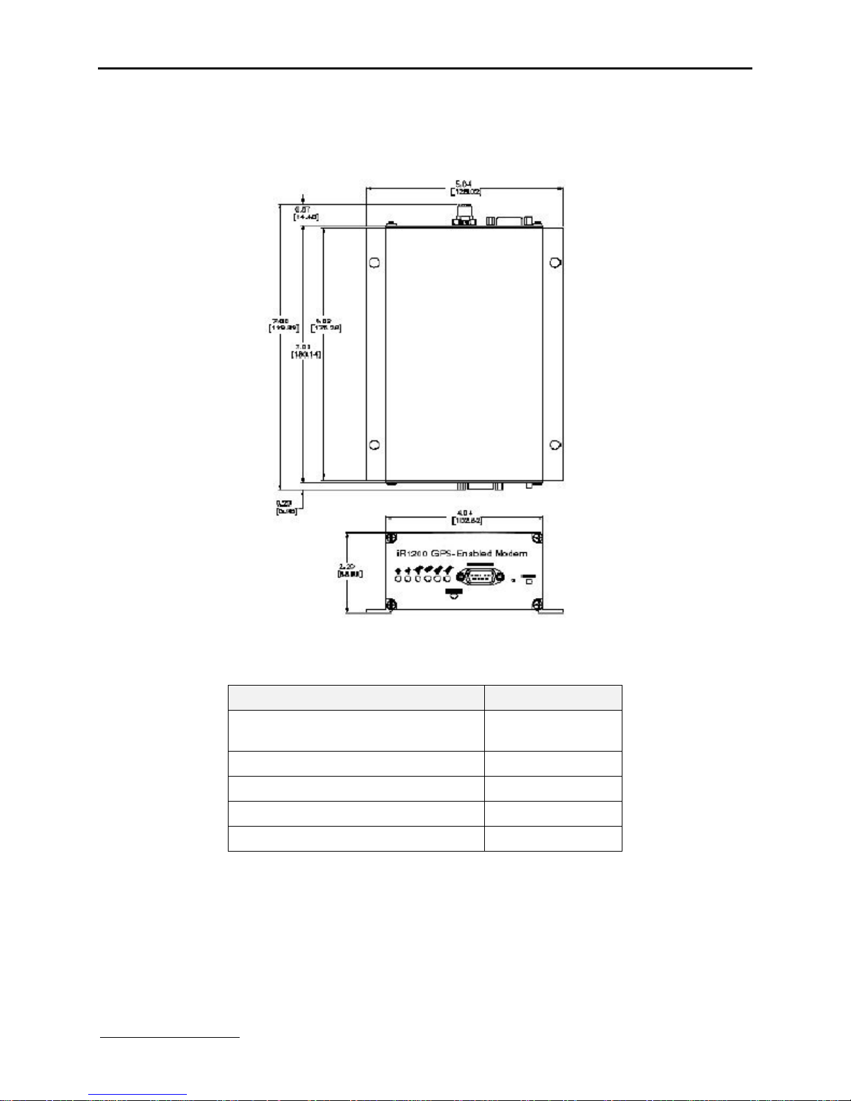
The followingdiagramoutlinesthemodem’sdimensions:
NOTE: Thisdiagramdepictsthe dimensionsof both theiR1200 Rugged and iR1200GPS-Enabled Modems and should
not beused asa templatefor mounting themodem.
Figure4 – Dimensions ofiR1200 GPS-EnabledModem
The followingtabledescribes theoveralldimensions of theiR1200modem.
Component Dimension
Overalldimensionsfromconnectorto
connector 7.86in.[199.69mm]
Endpanel toendpanel7.09in.[180.14mm]
Width(includingmountingtabs) 5.04in.[128.02mm]
Widthof enclosure4.04in.[102.62mm]
Height of enclosure2.20in.[55.88mm]
PlanningAntenna Location
Factors toconsiderwhenplanningforthelocationorplacementof the antenna:
•Choose alocationwitheasyaccess tocableroutingtoeasetheprocessof connectingtheantennatothemodem.
•Inmobileinstallation,mountthemodem antennaonthecenterof theoutsidetrunkforoptimumsignalreception.

TELUS Mobility™
10 www.telusmobility.com
•Inafixed(buildingor desk)environment, positiontheGPSantenna whereithasadirectline-of-sight tothesky. Insome
cases,thiscan beaccomplishedbyplacingtheantennaadjacenttoa window. Inmost casesit willrequiremountingoutside
of the building.
The cellular antenna(s) used for thistransmitter mustnot beco-locatedor
operated in conjunctionwith anyother antennaor transmitter. This device is
approved with emissions havinga source-based time-averagingdutyfactor
not exceeding 67.5%.
Vehicle–Antenna Installation:
•Antennas usedfor thistransmittermustnot exceed an antennagain of 5 dBd.
•For reardecktrunkandrooftopinstallations,theantenna mustbelocated at
least 20 cm awayfromrear-seat passengers andbystandersinorderto
complywith the FCCRF exposure requirements.
IMPORTANT: Failure toobserve these restrictionswill result inexceedingthe
FCC RF exposure limits.
PlanningCableLayout
Onceyouhavechosen the locationof themodem andantenna,andbefore installing,layout thecablestodetermine:
•If the cablescanreachthemodem andantenna.
•If the distancebetweencomponentsisadequateandallows youtomake adjustments toreceiveabettersignal.(Please refer
tothemanufacturer’s installationmanual forsafeinstallationof your antenna).
•If therearekinksorbendsinthecableorobstructionsinthevehicle thatcouldaffect routing.
Serial Cable Routing
Serial cableroutingisthemostimportantfactortoensureatrouble-free operation.Theserialcableshouldbeasstableaspossible
(e.g., itshouldexperiencelittletonomovementandhave fewornobendsorkinks).
NOTE: The majorityof problems occur because ofserial cablefailure.
Installation Tools
Youwillneedthesetoolstoinstall theiR1200modem.
•PortableDrill •Hammer
•CenterPunch •ConnectorCrimptool
•Four #10self-tappingsheet metal screws •PhillipsScrewdriver

iR1200Modem
www.telusmobility.com 11
MOBILE INSTALLATION
Inthischapter,youwilllearnhow toinstall your iR1200modemandantennasinamobileenvironment.
InstallationSteps Page11
Mounting theModem
SelectModemLocation
MounttheModem
Page11
Page11
Page12
Mounting theAntenna(s)
ApprovedAntennas
SelectAntenna Location
MounttheModemAntenna
MounttheGPS Antenna
Page12
Page12
Page12
Page13
Page13
RouteandConnectCables
ApprovedCable
RouteandConnectPowerCable
RouteandConnectIgnitionCable
RouteandConnectAntennaCable(s)
RouteandConnectDataCable(s)
Page13
Page13
Page14
Page15
Page15
Page15
OtherInstallationConfigurations
Continuous PowerConfiguration
ConfigurationforDockingStation
Page15
Page15
Page17
Installation Steps
Toinstall, youmustperformthefollowingsteps:
•Mount Modem– Mountthemodeminthedesiredlocation.
•Mount Antenna – Mount theantennausingthe instructionsincluded withyour selectedantenna’s installationguide.
•Mount GPSAntenna(GPS-Enabled Modemonly) – Mounttheantennausingtheinstructionsincludedwithyour GPS
antenna’s installationguide.
•Route andConnectPowerCable– routethepowercablefrommodemtothevehicle’spowersupply(ignitionswitch).
•Route andConnecttheIgnitionCable– Routetheignitioncable fromthemodemtothe ignition.
•Route andConnectAntenna Cable– Connect thecabletothemountedmodem andantenna.
•Route andConnectDataCable– Connectthedatacablefromthemodemtothemobiledevice.
Mounting theModem
Select Modem Location
The followingdescribestypical locations that youshouldconsiderformountingthemodem:
•Underseat •Intrunk •Centerconsole
•Underdashboard •Inaccessorycompartment

TELUS Mobility™
12 www.telusmobility.com
Mountedonsideof console
Mountedonsidewall of trunk
Mountthe Modem
The followingtable lists thestepsformountingtheiR1200 datamodem inamobileenvironment.
1Determineaconvenientlocationinthe mobileenvironment.
2Usethe iR1200 modemandmarkthepositionsof the holesonthe mounting surface.
3Drilltheholesinthe markedlocation.
4Mounttheunitusing the#10sheetmetalscrews.
Mounting theAntenna(s)
The locationof theantennashouldbechosencarefully.
!
Important things to consider when installing theantenna equipment.
•Equipmentmustbeinstalled inaccordancewithmanufacturer’s
instructions
•ToensurecompliancewithUnited StatesFCC regulations on RF
exposure,equipmentmustbe installed in suchawayastomaintaina
separation of at least 8 inches(20 cms) betweentheantennaand the
human body.
•Ensure thattheantenna is properlyinstalled external tothemobile
environment andin accordancewith therequirements oftheantenna
manufacturer/supplier.
•Useonlyan approved antenna. Unauthorized antennas, modifications or
attachmentscouldimpaircallquality, damagethemodem,or violateFCC
mandates.
Approved Antennas
Foralist of testedandapproved antennas that canbeusedwiththe iR1200modems,pleasecontact your authorizedTELUS
Mobility™dealer, go to www.elutions.com/wireless orcontact eLutions’WirelessSupportCenterat 888-349-4338.
NOTE: Antennaswith gainexceeding5dBd(commonlyspecified as 3dBgain) do not comply with FCCRF exposure and
are not allowed forusewith thisproduct.
!
IMPORTANT: Onlyapprovedandtestedcomponents should beusedwith the
iR1200modem.Useof unapproved components violatesthemodem’s
warranty.
Select Antenna Location
The followingaresomecommonlayoutsforco-locatinganexternal antennaandthe iR1200modem.
•Rooftotrunk –Thislayout accommodatesatrunk-mountedmodem andantenna thatisattachedtothe roof.
•Trunktotrunk –Thislayout accommodates atrunk-mountedmodemandantennathatisattachedtothetrunk.
•Rooftoconsoleordashboard –Thislayout accommodatesaconsoleordashboardmountedmodem andtheantenna
attachedtothe roof. Thissetupgivesyouaccess tothemodem.

iR1200Modem
www.telusmobility.com 13
The cellular antenna(s) used for thistransmitter mustnot beco-locatedor
operated in conjunctionwith anyother antennaor transmitter. This device
is approved with emissions having a source-based time-averaging duty
factor not exceeding 67.5%.
Vehicle–Antenna Installation:
•Antennas usedfor thistransmittermustnot exceed an antennagain of 5 dBd
(commonlyspecified as 3dB gain).
•For reardecktrunkandrooftopinstallations,theantenna mustbelocated at
least 20 cm awayfromrear-seat passengers andbystandersinorderto
complywith the FCCRF exposure requirements.
IMPORTANT: Failure toobserve these restrictionswill result inexceeding
the FCC RFexposure limits.
Mountthe Antenna(s)
Mount Modem Antenna
The followingtabledescribes thesteps formountinganantenna.
1Usean antenna suitableforthecellularband of frequencies(806-870MHz) withMiniUHFjackand
matchedfor50-ohm impedance.
2Mountthe antenna accordingtothe manufacturer’s specificationsorinstructions.
NOTE: Each antenna hasspecific installation instructions. Please refer to theantenna installation instructions for
specific requirements and details.
Mount GPS Antenna (optional)
The iR1200GPS-Enabledmodemcomes equippedwithaconnectorforaGPSantenna. Thefollowingtablecontainsthestepsfor
mountingaGPSantenna.
1Usean antenna suitablefortheGPS of frequency1575 MHzwithanMCX connectorandmatchedfor50-
ohmimpedance. (Useonlyan approvedantenna–see availableand approvedAntennas oneLutions’
website, www.elutions.com/wireless).
2Positiontheantennawhereit has adirectline-of-sighttothe satellite.
3Mountthe antenna accordingtothe manufacturer’s specificationsorinstructions.
NOTE: Because of theoperating frequenciesinvolved with the GPSsignal,splicingor using adaptersto extend the
length of theantennacoaxialcable is not recommended and willlikelypreventthe system fromoperating
properly. We recommend thata single length of coaxwithout splices or adaptersbe used.
Routeand Connect Cables
Approved Cable
The followingDCpowercablewasdesignedspecificallyforusewiththeiR1200.Toorder this requiredcomponent, please
contact your authorizedTELUSMobility™dealer,go to www.elutions.com/wireless or contact eLutions’WirelessCustomer
SupportCenter at 888-349-4338.
5100-C5-RFM –VehiclePowerHarness

TELUS Mobility™
14 www.telusmobility.com
The followingdiagramillustratestypicalinstallationwiringof theiR1200intoamobileenvironment.
+12VDC
VEHICLEBATTERY
+12VDC
ENGINE IGNITION
SWITCH
FUSE
GPSANTENNA
(OPTIONAL) MODEM
ANTENNA
iR1200
POWER
IGNITION
MOBILEDATA
COMPUTER
RS-232
GPS DATA
RS-232
MODEM DATA
Figure5 –iR1200 InstallationWiring Diagram (Mobile)
Route andConnectPower Cable
RoutetheDCpower cableusingthefollowingdiagramasaguideline:
Figure6 –Modem Power WiringDiagram
The followingtablecontainsthestepsforroutingandconnectingthepowercable:
1Determineacable routingplanthatwillallow youtoconnecttheDCpowercablebetweenthemodem
andthevehiclebattery. Connectthe maleendof thepowercabletothe2-prongconnectorlabeled
POWERonthe modem.
2Routethefree endof thecabletothevehiclebattery. Ifnecessary, drilla holeinthevehiclefirewall and
routethecablethroughitusing thesuppliedgrommet(RefertoFigure6–ModemPowerWiring Diagram
onpage14).
3Locateanavailablechassis groundmountingpoint nearthebatteryand shortentheblacklead toremove
anyexcess cablelength.
4Crimponthering tongue terminalandconnecttheblack leaddirectlytothechassis ground.
5Positionthefuseholderas closetothebatteryas possible, and awayfromanypotentiallyhotcomponents.
6Mountthefuse holderbytiewrappingittotheothercablingwiresanddress wiresas necessary.
7Shortentheredlead of theDCpowercabletoremove anyexcess lengthandcrimp thefuse holder’s red
lead toitusing thein-linesplice.
8Connectthe ringtongue terminalfromthefuse holdertothe positive (+) batteryterminal.
This manual suits for next models
1
Table of contents
Other TELUS Modem manuals


