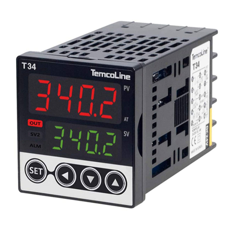
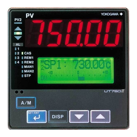
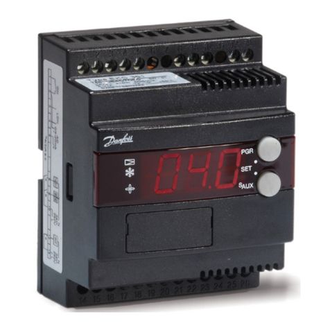
Temcoline T52 User manual

T50 SERIES PID Controller
User's Manual
T50 series
T52 T53 T54 T57 T59
www.temcoline.com
HEATING
&
COOLING
Selectable for All models

임의의 (위치)
설정 메뉴에서
SET키를 누른 상태
에서 UP키를 누르면
해당되는 상위(그룹)메뉴로 순간 점프하여 빠르게
원하는 메뉴로 이동할 수 있습니다.
※순간이동 기능!
편리한 기능
※ 순간이동 기능을 사용하십시오!
설정속도가 최대 10배 까지 빨라집니다.
※ Function
of menu return
Useful Features !
※ Use the menu return function to speed up
the setting up to 10 times faster.
If you press the up key
while pressing the set key
in any setting menu,
you can move to the
corresponding upper menu
and move to the desired menu
immediately.
F
u
n
c
t
i
o
n
o
f
m
e
n
u
r
e
t
u
r
n

www.temcoline.com
DIGITAL PID CONTROLLER
Thank you for purchasing the T50 series from TemcoLine.
The T50 series is a precision industrial controller that uses an advanced 2
degree-of-freedom (DOF) algorithm.
The T50 series consists of 5 models, which are T52, T53, T54, T57, and
T59.This manual explains the installation, the functions, the operation,
and the handling of the products.
Please read the manual thoroughly before using the products. If any
difficulties arise while using our products, please call our customer service
at +82-1588-5439.
2
- Use the products under the conditions specified in this manual.
- Please heed the cautions and warnings listed in this manual.
- The contents of the manual may be changed without notice.
- The product is designed to be used installed on a control panel.
- This manual is copyrighted, and may not be copied in part or in whole
without permission.
- The manufacturer takes no responsibility for direct or indirect damages
caused by careless operation or operation under unpredictable or risky
environments.
Safety requirements are intended to prevent accidents and dangers
through the proper use of the products, so please heed them at all times.
The safety requirements are divided into "cautions" and "warnings", which
indicate the following.
WARNING
CAUTION
Pay attention to the followings!
Safety requirements!
Serious injury or death may be caused if instructions are not observed.
Failure to observe these instructions may cause damage to the instrument
or some injury to the user.

www.temcoline.com
DIGITAL PID CONTROLLER
1. Use a separate safety device when this product is used to control a
device that could harm lives or expensive property in the event of a
malfunction or a breakdown. (This may cause fires, deaths, or damage
to property.)
2. Do not use this controller at place where there are flammable or
explosive gas. (It may cause a fire or explosion.)
3. Before turning the power on, please check that wiring is correct to
the number of terminal. (It may cause a fire.)
4. Turn off the power during wiring and maintenance to avoid an electric
shock.
5. Do not touch the terminals when it is power on. (It may give an electric
shock.)
6. This controller must be mounted on the panel to avoid an electric
shock.
7. Do not attempt to disassemble, modify and repair.
1. Please conduct an inspection when water has entered the product.
(It may cause short circuits, fires, and malfunction.)
2. This controller should be used indoors.(It may shorten the controller's
life or give an electric shock.)
3. Observe the rated voltage and specification.(It may cause a fire or
shorten the controller's life.)
4. Be careful that any of foreign materials do not inflow into the
controller. (It may cause a fire or malfunction of the controller.)
5. Do not give direct vibration or shock to the controller. (It may cause
of malfunction of the controller.)
6. Do not use chemical detergent or solvent, but use a dry towel in
cleaning the controller. (It may cause an electric shock or a fire.)
7. Please check the polarity of power before wiring and connecting the
sensor.(It may cause an electric shock or explosion.)
3
WARNING
CAUTION

www.temcoline.com
DIGITAL PID CONTROLLER
1. Ordering Information
2. Input ranges & Output constitutions
3. Dimensions & Panel cutouts
4. Terminal Arrangements & Wirings
5. Ratings & Specifications
6. Features & Function
7. Check points before Using
8.
Initial installation & Min. operation procedures
9.
Entering into "set menu" and Setting method
10. Flow Chart (Parameter structure)
11. Easy function & Safety function
12. Functions of each setting group
1) Control group setting
2) Set value(SV) group setting
3) Auto tuning(AT) group setting
4) P.I.D group setting
5) Heater ammeter &
HBA group setting
6) Alarm(ALARM1,2,3) group setting
7) Retransmission group setting
8) Communication group setting
9) Output group setting
10) Input group setting
11) Error indication during operation
Contents
4
5
19
32
11
21
35
17
31
24
38
7
20
34
15
29
23
37
18
31
29
41
43
45

www.temcoline.com
DIGITAL PID CONTROLLER
Code Model Size Remarks
2
3
4
7
9
0
1
T52-SERIES
100 ~ 240V AC General-purpose usage
Alternating or Direct current usage
T53-SERIES
24V AC or DC
T54-SERIES
T57-SERIES
T59-SERIES
48(W) x 96(H) x 77(D) Option: 0, 1, 2
Option: 0, 1, 2
Option: 0, 1, 2, 3, 4, 5, 6, 7
Option: 0, 1, 2
Option: 0, 1
96(W) x 48(H) x 77(D)
96(W) x 96(H) x 77(D)
48(W) x 48(H) x 77(D)
72(W) x 72(H) x 77(D)
1. Ordering Information
(1) Size
(2) Control mode
(4) Power supply voltage
5
(1)
Size
(3) Optional function
(2) Control mode
(4) Power supply voltage
S
C
L
SINGLE
Heating or Cooling control
Normal type (Single) + Heating / cooling type (Dual) integration
Dedicated product for monitoring and controlling the
temperature for safety
COMBINE
LIMIT CONTROLLER
T 5 -
Code Description Remarks
Code Description Remarks

www.temcoline.com
DIGITAL PID CONTROLLER
(3) Optional function
T52-SERIES
T53-SERIES
T54-SERIES
T57-SERIES
T59-SERIES
Basic
function
RELAY output 1(MAIN/Alarm 3), Alarm output 2,
SCR(4~20mA), SSR(Voltage pulse) 1,
RET(4~20mA Retransmission output)
RELAY output 2 (ALARM & MAIN OUTPUT),
SCR(4~20mA), SSR(Voltage pulse) 1
RELAY output 1, Alarm output 2,
SCR(4~20mA), SSR(Voltage pulse) 1
Communication RS-485
(MODBUS-ASCII, RTU)
,
RET(4~20mA Retransmission),
HBA(CT) Heater current & Break Alam
RELAY output 1, Alarm output 2,
SCR(4~20mA), SSR(Voltage pulse) 1,
RET(4~20mA Retransmission)
D.I(SV2, 3), RET(4~20mA Retransmission),
HBA(CT) Heater current & Break Alam
Communication RS-485(MODBUS-ASCII, RTU),
HBA(CT) Heater current & Break Alam
Communication (RS-485), Alarm output 2
D.I (SV1, 2, 3) External digital input
Communication RS-485(MODBUS-ASCII, RTU)
Heater ammeter & HBA(CT) Heater break alarm
Basic function +
(Option code)
Basic function + Option code
(0 : No option)
Basic function + Option code
(0 : No option)
Basic function + Option code
(0 : No option)
Ex.) T52, T53-C00
Ex.) T54-C10
Ex.) T57-C10
Ex.) T57-C20
Ex.) T59-C10
Ex.) T54-C20
Ex.) T54-C30
Ex.) T54-C40
Ex.) T54-C50
Ex.) T54-C60
Ex.) T54-C70
Ex.) T52, T53-C10
RET(4~20mA Retransmission), Alarm output 2
HBA(CT) Heater current & Break Alam, Alarm output 2
D.I(SV2, 3) External input, Alarm output 2
0
0
0
0
1
1
1
1
2
2
3
4
5
6
7
RET(4~20mA Retransmission),
Communication (RS-485)
HBA(CT) Heater current & Break Alam,
Communication (RS-485)
D.I(SV2, 3) External input,
Communication (RS-485)
6
1) Example of model building
Model Code Description Remarks
(1) Size : 48(W) x 48(H) x 77(D)
"4"
"C"
"1"
"0"
(3) Optional function : RET, Alarm output2
(2) Control mode : COMBINE
(4) Supply voltage : 100~240V AC
Ex.)T54-C10
T54-C10

www.temcoline.com
DIGITAL PID CONTROLLER
2. Input ranges and Output constitutions
1) Input ranges
※
The T50 series has multiple inputs, which may be set and changed by the user.
7
※ How to change the interior switch when using 1~5V input
① Remove plate or take
out the main cover.
② Move and insert the jumper
that pulled by tweezers.
③ Relocated jumper as above
and attach plate or mounted
cover.
* F.S is max. value
to min. value of
each range.
* Digit is minimum
of display.
※ When using 1~5V input
(30), the interior jumper
switch must be relocated.
When using current
input, use the resistor
250Ωon input terminal.
Input type Input
Code
Temperature range Remarks
Accuracy
K
J
E
T
R
B
S
L
N
U
C (W5)
D (W3)
JPt100Ω
(JIS, KS)
Pt100Ω
(DIN, IEC)
0~100mV DC
-10~20mV DC
1~5V DC
4~20mA DC
1
2
15
3
16
4
5
6
7
8
17
9
10
14
11
12
13
20
22
21
23
33
32
30
30
±0.3% of FS
+ 1 Digit
RTD
Voltage
(V DC/mV DC)
Current
-200 ~ 1370
-199.9 ~ 999.9
-200 ~ 1000
-199.9 ~ 999.9
-200 ~ 1000
-199.9 ~ 999.9
-199.9 ~ 999.9
-199.9 ~ 400.0
0 ~ 1700
400 ~ 1800
0 ~ 1700
-200 ~ 900
-199.9 ~ 900.0
-200 ~ 1300
-199.9 ~ 400.0
0 ~ 2300
0 ~ 2400
-199.9 ~ 500.0
-200 ~ 500
-199.9 ~ 640.0
-200 ~ 640
0 ~ 100mV DC
-10 ~ 20mV DC
1~5V DC
Thermocouple
(T.C)
MULT-IN MODE IN 1~5V ONLY MODE

www.temcoline.com
DIGITAL PID CONTROLLER
8
2) Output configuration
(1) Alarm output configuration
T50 SERIES can use up to three different alarm outputs for 21 different types.
In addition, the unique output configuration of the system allows the user to
designate the output port freely, and the alarm 1 ~ 3 outputs can be exchanged
or used together.
A1Pn~A3Pn(AL1~3)
경보1 종류 설정
(번호 1 ~ 21)
경보2 종류 설정
(번호 1 ~ 20)
경보3 종류 설정
(번호 1 ~ 20)
경보3 데드밴드 설정
(히스테리시스 [℃])
경보3 설정값
(알람설정 [℃])
경보1 출력포트 설정
(AL1, AL2, AL3)
경보2 출력포트 설정
(AL1, AL2, AL3)
경보3 출력포트 설정
(AL1, AL2, AL3)
경보1 지연시간 설정
(OFF / 1 ~240초)
경보2 지연시간 설정
(OFF / 1 ~240초)
경보3 지연시간 설정
(OFF / 1 ~240초)
Press and hold for
more than 3 seconds
short
shortly 5 times
Alarm 1 type setting
(No. 1~21)
Alarm 2 type setting
(No. 1~20)
Alarm 3 type setting
(No. 1~20)
Alarm 3 Setting value
(Alarm setting [℃])
Alarm 3 Dead band setting
(Hysteresis [℃])
Alam1 delay time setting
(off/1~240 sec)
Alam2 delay time setting
(off/1~240 sec)
Alam3 delay time setting
(off/1~240 sec)
ALARM3 enabled when
output SSR(1) or SCR(2)
is set
Alarm 1 and Alarm 2
dedicated outputs
ALARM3
enabled when
output SSR(1)
or SCR(2) is
set
ALARM3
enabled when
output SSR(1)
or SCR(2) is
set
T54-C0x, C4x, C5x, C6x
(The default alarm option model)
① Outoput relay(3)
A2TY OFF
② Outoput relay(3)
ALARM 2
③ Outoput SSR(1)
or SCR(2)
T54-C1x, C2x, C3x, C7x
(Additional Alarm Option Models)
Alarm setting group
A1Pn~A3Pn(AL1~3)
Alarm 1 output port setting
(AL1, AL2, AL3)
Alarm 2 output port setting
(AL1, AL2, AL3)
Alarm 3 output port setting
(AL1, AL2, AL3)

www.temcoline.com
DIGITAL PID CONTROLLER
※ Detailed description related to setting of control and alarm output port
① Basically, the T50 series output supports a total of three event outputs, each of
which consists of 21 types.
② Basically, alarm 1 is set to AL1 port, alarm 2 is set to AL2 port, and alarm 3 is set
to AL3 port. However, if necessary, the output port can be used in combination or
a single output port can be used It provides a powerful function that can logical
sum or OR the alarms 1 to 3.
☞ When alarms 1 to 3 are set to one port, it is necessary to set only one of the
process high and process low, or if the process high and the process low are mixed
and the port is specified as one port, process high.
③ When the cooling output is set to RELAY (3) by selecting the heating / cooling
dual control mode, the AL2 (OUT2) port is used as the cooling control output.
④ In case of model without alarm option of T54 (48x48mm), the main control output
(①, ②, ③) port can be automatically changed to various output contact according
to the setting and can be used as maximum 2 relay contact output.
9

www.temcoline.com
DIGITAL PID CONTROLLER
(2)
Setting of heating and cooling control PID control mode
Press and hold for
more than 3 seconds
Selecting Output Operation (REV, DIR, DUAL)
REV : Heating control
DIR : Cooling control
Dual : Heating and cooling control
Use or , key to adjust the setting number corresponding to the output type, and then save it
using key.
※ Caution!
In Heating & cooling mode, control output uses alarm 2
output, so must be change to alarm 1 or alarm 3 when
using alarms.
Cycle time in heating (output 1) SSR or relay
※ It is not used in the SCR (4 to 20 mA) mode,
so it will not be displayed.
Cycle time in Cooling (output 2) SSR or relay
※ It is not used in the SCR (4 to 20 mA) mode,
so it will not be displayed.
The cooling gain setting range can be set from 0.1 to 10.0
※ Explanation of operation according to dead band value
The default value is set to 0.0% and does not need to be
set except in special cases.
output
of heating
output
of heating
output
of cooling
output
of cooling
T50 SERIES
(3)
Dead band setting
It is used only for heating / cooling control and sets the dead zone area of
heating and cooling.
Example) Model T54-C10
SSR P.I.D 제어
SCR (4~20mA) P.I.D 제어
RELAY P.I.D 제어
⑪, ⑫
⑪, ⑫
⑭, ⑮
1
2
3
PID group menu
Select group (default)
Dead band setting
(-100 ~ 100%)
short
※
Press and hold key for more than
3 seconds in any menus to return to Normal
operation mode. After the auto tuning is
completed, the entry of the input and
output setting menu is automatically blocked.
Please refer to the instruction manual if
reset and release are required.
PV
SV
PV
SV
T54
D.I
Cooling Gain
GCO Operation
Heating side
proportional band Cooling side
proportional band
0 PV
output Gco > 1.0
Gco = 1.0
Gco < 1.0
+ value(Dead band)
- value(Overlap band)
0 PV
output output
Set value(target) Set value(target)
0 PV
Output
selection
number
Output
terminal
RELAY ON/OFF control
SSR P.I.D control
SCR (4~20mA) P.I.D control
RELAY P.I.D control
Example) Model T54-C10
①, ②, ③
⑥, ⑦
⑥, ⑦
①, ②, ③
0
1
2
3
Output
selection
number
Output
terminal
Heating or cooling
control (output 1)
Heating or cooling
control (output 2)
Only displayed during dual (heating and cooling) control
10

www.temcoline.com
DIGITAL PID CONTROLLER
3. Dimensions and Panel cutouts
11
1) T52 (48x96 mm) Dimensions
2) T53 (96x48 mm) Dimensions
3) T54 (48x48 mm) Dimensions
10.0 77.0
96.0
91.0
48.0
96.0
96.0
48.0
48.0
43.6
10.0 77.0
8.8
48.0
44.9
48.0
77.0
48.0
T52 / T53 (96x48)
Panel cutouts
(Unit: mm)
45±0.5
92±0.5
Min. 30
Min. 20
T54 (48x48) Panel cutouts
(Unit: mm)
Min.17
Min.17
45 +0.5
-0
45 +0.5
-0

www.temcoline.com
DIGITAL PID CONTROLLER
12
4) T57 (72x72 mm) Dimensions
5) T59 (96x96 mm) Dimensions
72.0
9.0 77.0
72.0
67.0
72.0
77.0
96.0
91.0
10.0
96.0
96.0
(Unit: mm)
(Unit: mm)
T57 (72x72) Panel cutouts
(Unit: mm)
Min.20
68±0.5
68±0.5
Min.30
T59 (96x96)
Panel cutouts
Panel cutouts
CTL-6-S (U-RD)
TS-9W(Temcoline)
Min.20
92 ± 0.5
92 ± 0.5
Min.30
※ HBA option (Heater break alarm)
Current transformer (CT) : using 800:1 CT of TS-9W or CTL-6-S

www.temcoline.com
DIGITAL PID CONTROLLER
6) Installation
(1) T54-SERIES
(2) T52/ T53/ T57/ T59-SERIES
① Bore a hole in the panel, referring to the panel cutouts on the previous page.
② Insert this device into the front of the panel.
③ Insert 2 brackets, one each on the bracket holes on the top and the bottom
of the device.
④ Secure using screws on the two locations at top and bottom.
13
[ figure 1 ] Top side [ figure 2 ] Bottom side [ figure 3 ] Fixing completion
Hole of fixing screwHole of fixing screw
Bracket hole
Bracket hole
Bracket hole Turn the screw
2-3 times after
contact with panel.
Panel Panel
① Process the mounting hole referring to the panel machining dimensions of
the previous page on the panel.
② Insert this device from the front of the panel.
③ After inserting the two brackets into the holes of the left and right brackets
of the device, Slide it until it fits tightly to the panel and secure it.

www.temcoline.com
DIGITAL PID CONTROLLER
14
7) Terminal wiring method
(1)SCREW
① When wiring the terminal, tighten the screw with a tightening torque of
0.74 to 0.90 N.m.
(2) Cautions for terminal wiring
① Signal lines and power lines should be separately wired to avoid the effects
of noise
② Use a crimp terminal to wire the terminals.
③ Tighten the terminal screws with a tightening torque of 0.74 to 0.90 N.m.
④ Please use the following form of crimp terminal M3.5.
SCREW
Crimp terminal
Less then 7.2 mm
Less then 7.2 mm

www.temcoline.com
DIGITAL PID CONTROLLER
15
4. Terminal Arrangements and Wirings
1) T52 (48x96 mm), T53 (96x48 mm)
2) T54 (48x48 mm)
D.I 1
D.I 2
OPTION
OPTION1
(T52-S10)
(T53-S10)
OPTION1
(T54-C1X)
OPTION2
(T54-C2X)
OPTION4
(T54-C4X)
OPTION6
(T54-C6X)
OPTION5
(T54-C5X)
OPTION7
(T54-C7X)
OPTION2
(T52-C10)
(T53-C10)
OPTION
D.I
T52
T53
T54
D.I D. I
D.I D. I
OPTION3
(T54-C3X)
D.I
D.I
D.I D. I
D.I D. I
D.I
D.I
D.I D. I

www.temcoline.com
DIGITAL PID CONTROLLER
16
※ Terminal explanation (T59-S10 basis)
Terminal : OUT1 only for output
selection no. 0, 3 (Relay output) mode.
Terminal : OUT1 only for output.
selection no. 1, 2 (SSR, SCR output) mode.
Terminal : RET(Retransmission 4~20mA)
or for power of sensor SPS. (DC 15V)
Terminal : Power supply terminal.
Terminal : Alarm1 output terminal.
Terminal : Alarm2 output terminal.
Terminal : C.T(800:1) input terminals
for Heater break alarm.
Terminal : It is an external input (DI)
terminal. various functions can be set with
external switches according to DIS 1-5 (1: OFF,
2: SV 1-3, 3: run / stop 4: 4: auto / manual
5: alarm reset).
Terminal : The input sensor type is
changed according to the input setting number
with the univeral input terminal.
Terminal : RS-485 communication
terminals completely isolated, Modbus-ASCII,
Modbus-RTU, PC-Link, TL-Link basic.
D.I 1
D.I 2
D.I 1
D.I 2
OPTION
OPTION 1 (T59-C1X)
3) T57 (72x72 mm)
4) T59 (96x96 mm)
T57
T59
OPTION 1
(T57-C1X)
OPTION 2
(T57-C2X)
D.I 1
D.I 2
D.I 1
D.I 2

www.temcoline.com
DIGITAL PID CONTROLLER
17
5. Ratings and Specifications
T50 SERIESModel
Power Supply
Power Consumption
Dispaly Accuracy
Control
Output
Alarm
Output
ALARM 1, 2
HBA common
(C.T)
Relay
Voltage
(S.S.R)
Current
(S.C.R)
Input Impedance
Input Sampling Period
Control Method
Multi SV Input(D.I)
Retransmission
Output
Communication
Output
Ambient Temperature
and Humidity
Weight
(Bracket, Accessories included)
Input Type
5VA (Max.)
±0.3% of FS +1 Digit
50~250ms (variable according to SG-PID algorithm)
DC15V 25mA (Built-in short protection circuit)
Voltage pulse (time proportional PID output)
4~20mA DC, load impedance ≤ 600Ω(continuous PID output)
Super 2 degree-of-freedom PID (SG-PID algorithm),
S-Fuzzy, Auto-Tuning
ON: ≤ 1KΩ, OFF: ≥ 100KΩ(external control SV1, 2, 3)
TC: K, J, T, E, R, B, S, L, N, U, C(W5), D(W3)
Platinum RTD: KPt100(KS), JPt100(JIS), Pt100(DIN)
Current input(A): 4~20mA DC
Voltage input(V): 1~5V DC, -10~20mV DC, 0~100mV DC
2 wires RS485 totally independent isolation structure
Max. speed: 19,200bps/ Max. connect no. 99 devices (32
devices recommended) Support protocol: PC-Link, TL-
Link, Modbus-ASCII, Modbus-RTU
Rating 100~240V AC 50~60Hz (voltage operating range: 85~265V AC)
※ Option: Rating 24V AC or DC (operating voltage range 20~28V DC)
Current input(250Ω), Voltage input(including TC) 1MΩmin.
(RTD line resistance: ≤ 10Ω, when 3-line resistance are
the same)
1c 250V AC, 3A(resistance load) electric lifespan ≥ 100,000 min.
(time proportional PID output or ON/OFF output)
4~20mA DC, load impedance ≤ 600Ωresolution 1/4,600
PV(process value), SV(set value), MV(manipulated variable [%]),
SPS(sensor module power supply)
1a 250V AC 3A (Resistive load)
HBA: 0.1 ~ 38.0 A AC (Resolution 0.1A)
-10~50℃/ relative humidity 25~85% RH
(but with neither condensation nor freezing)
T52, T53, T57: 230g T54: 140g T59: 320g
※ + 30g, if options are added

www.temcoline.com
DIGITAL PID CONTROLLER
18
6. Features and Function (ex. T54-SERIES )
① Process value (PV)
display (Red color)
② Auto tuning (AT) lamp
③ Set value (SV)
display (Green color)
④ Control output lamp
⑨ Set value Down key
⑧ Shift key
⑦ Storage & Function key
⑤ SV2 display lamp
⑩ Set value Up key
⑪ Cooling output lamp (for dual
control)
⑥ Alarm output lamp
※ Description
NAME FUNCTION
Display the process value. (red color)
Flash every 0.5 second during auto tuning.
Display the set value, codes, and modes.
Lights when the control output is ON.
Lights when the SV2 is displayed.
Lights during the alarm is ON.
Use to move the menus, to store, and to operate.
Use to shift the digits.
Use to decrease set value and to move the menu.
Use to increase set value and to move the menu.
Displays cooling output during heating/ cooling control.
① Process value
② Auto tuning lamp
③ Set value display
④ Control output lamp
⑤ SV2 display lamp
⑥ Alarm output lamp
⑦
Function key
⑧
Shift key
⑨ Set value down key
⑩ Set value up key
⑪ Cooling output lamp

www.temcoline.com
DIGITAL PID CONTROLLER
19
2) 7 Segment display indications
7. Check points before Using
1) Default values at the point of manufacture
The default input and output values of the product at the point of manufacture
are as follows.
Input : K-Type (Code No. 1) Output : SSR (Code No. 1)
※ In the case of the basic model of T54-S00 only, when SSR(1) or SCR(2) is chosen
as the output mode, Alarm 1 output will be in main relay.(Refer to page 8 for
details.)
3) Initial display on power supply (T54 SERIES basis)
Model Name
Firmware version display
Output type indication
Input type indication
0 :
Basic type (No option)
1
:
RET, ALARM1, 2
2 : HBA(CT), ALARM1, 2
3 : DI, ALARM1, 2
4 : RET, RS-485
5 : HBA(CT), RS-485
6 : DI(SV1, 2), RS-485
7 : RS-485, ALARM1, 2
0 : RELAY ON/OFF control
1
:
SSR (
VOLT-PULSE) PID control
2 : SCR (4~20mA) PID control
3 : RELAY PID control
01
: K-Type (-200~1370 ℃)
02 :
K-Type (-199.9~999.9 ℃)
33 :
mV DC (0~100mV)
Option indication
This manual suits for next models
5
Table of contents
Other Temcoline Controllers manuals
Popular Controllers manuals by other brands
intensity
intensity KJR-12B/DPBG(T)-E owner's manual
Precision Digital Corporation
Precision Digital Corporation ConsoliDator PD980-8K9-15 instruction manual
fakro
fakro ZWS12 user manual
Allen-Bradley
Allen-Bradley powerflex 700 installation instructions
Lenze
Lenze SCL series Installation and operaion manual
Parker
Parker Gemini GV6K Series Quick reference guide
