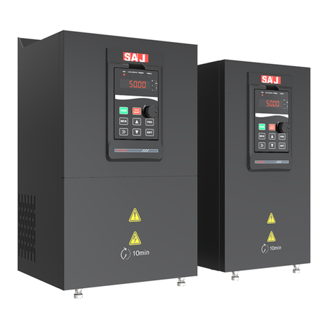
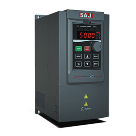
SAJ VM1000 User manual

VM1000 Series
‐0‐
资料代码:
VM1000 AC Drive
User Manual
Version Code :VM1000-E2016-04-1MB

VM1000 Series
‐1‐
Preface
Thank you for choosing SAJ VM1000 AC drive.
This user manual provides you with technical specification, installation instruction
and detailed function parameters of VM 1000.Before installation, operation,
maintenance or inspection, please read this manual carefully.
Special warning: Please be sure to read and understand the warnings and precautions
in this manual before using VM 1000 and make sure the certificate of relative
electrical engineers is line with the provisions of the labor supervision
department, and the electrics and environment conditions is in conformity with the
country’s standard.
Make sure the wiring is correct before it is power-on; before normally operating and
using this product, make sure the motor rotation meets the requirements by
debugging it.
When installing, using or maintaining the product, if it needs a consultation for
product functions, performance, other technical issues as well as safety precautions,
please contact our customer service center according to the hotline in the manual.
China service hotline: 400-159-0088

VM1000 Series
‐2‐
Content
Preface.............................................................................................. - 1 -
Precautions ...................................................................................... - 4 -
Signs, Abbreviation and Brandmark statement........................... - 8 -
Chapter 1 Product Information.....................................................- 9 -
1.1 Production Introduction ................................................................................. - 9 -
1.2 Technical Specification Table ...................................................................... - 10 -
1.3 Product nameplate........................................................................................ - 13 -
1.4 Model Description ....................................................................................... - 14 -
1.5 Dimension of AC Drive ............................................................................... - 14 -
1.6 Dimension of Keyboard............................................................................... - 17 -
1.7 Specification of Selecting Products ............................................................. - 18 -
1.8 Maintenance................................................................................................. - 19 -
Chapter 2 Installation................................................................... - 22 -
2.1 Mechanical Installation................................................................................ - 22 -
2.2 Electrical wiring........................................................................................... - 28 -
2.3 Electro Magnetic Compatibility................................................................... - 43 -
Chapter 3 Panel Display and Operation...................................- 46 -
3.1 Introduction of Operation&Display Interface.............................................. - 46 -
3.2 Function Code Viewing, Modification Instruction ...................................... - 49 -
3.3 Viewing Methods of Status Parameters ....................................................... - 50 -
3.4 Password Setting........................................................................................ - 50 -
Chapter 4 Quick Debugging Guide .............................................- 51 -
4.1 Preparation and Examination Before Commissioning Operation................ - 51 -
4.2 Panel Operation............................................................................................ - 53 -
4.3 Start/Stop control of terminal forward rotation ........................................... - 56 -
4.4 Common Control Guideline......................................................................... - 58 -
4.5 Auto-tuning of Motor Parameters ................................................................ - 62 -
4.6 Faults Query and Reset step......................................................................... - 64 -
4.7 Parameters Restore as Factory Value........................................................... - 65 -

VM1000 Series
‐3‐
Chapter 5 Function Code Datasheet.........................................- 66 -
Chapter 6 VM1000 Communication Application..................... - 112 -
6.1 The Content of Protocol............................................................................. - 112 -
6.2 Application................................................................................................. - 112 -
6.3 Bus Structure.............................................................................................. - 112 -
6.4 Protocol Instruction.................................................................................... - 113 -
6.5 Communication Frame Description........................................................... - 113 -
6.6 Register Address ........................................................................................ - 118 -
Chapter 7 Faults and Solutions ............................................... - 126 -
7.1 Fault Code Table........................................................................................ - 126 -
7.2 Troubleshooting and Solution.................................................................... - 138 -
Appendix A -Selection of External Electrical Components..... - 140 -
A.1 VM1000 External Electrical Connection Diagram................................... - 140 -
A.2 Selection Guide of Braking Components ................................................. - 143 -
A.3 Selection of Air Switch,Contactor or Cable.............................................. - 145 -
Appendix B-Manual Revision Record....................................... - 146 -

VM1000 Series
‐4‐
Precautions
The Definition of Manual Warning Signs
In this manual, there are three kinds of warning signs that is respectively
corresponding to three kinds of precautions; once violated, it will probably cause
person injury to different degree.
DANGER: it indicates that it will probably cause death or severe physical
injuries if violate the correct instruction.
WARNING: it indicates that it could cause personal moderate injuries, minor
injuries or damage to the equipment if violates the correct instructions..
NOTE: it indicates that it would cause error or using equipment insecurely if
violates the correct instruction.
The Definition of Product Warning Signs
The product warning signs are right under the case cover.
It indicates that there is high voltage in the product
+10 minutes time delay, which indicates that it needs to wait for capacitor
discharging after power off
Before Installation
Before opening, please confirm that:(1) model and rated values on the nameplates
is same as the goods you order; products, certification accessories, user manual and
warranty card are complete and have not been damaged;(2) Whether the products
are damaged or destroyed with water etc.; If there is damages,losses or other
abnormal phenomenon,please contact our company or your suppliers to solve
problems

VM1000 Series
‐5‐
Warning
◎Do not install or operate the VFD if it is damaged or has missing parts. Otherwise it may
result in equipment damage or physical injuries.
Installation
Warning
◎Please hold the bottom of VFD when installing or moving it. In case that the VFD is
broken or damaged; only holding the shell is not allowed.
◎Keep the VFD away from heat, inflammable and explosive goods; Install VFD on the
metal or other nonflammable objects.
◎If the VFD is mounted in an electric cabinet or other enclosed objects, fans or other cooling
device should be installed inside the cabinet; Setting ventilation opening to ensure ambient
temperature is below 40℃. Otherwise it may be damaged because of high temperature.
Danger
◎Wiring must be completed by qualified electrical engineers. Otherwise it can cause an
electrical shock or VFD damage.
◎Before wiring, make sure the power supply is de-energized. Otherwise it will cause an
electrical shock or a fire.
◎Make sure the ground terminal is grounded safely and correctly. Otherwise there will
be a risk of electrical shock on the shell of VFD.
◎Do not touch the main circuit terminal, and the main circuit terminals of the VFD are not
allowed to contact the shell. Otherwise it may cause an electrical shock.
◎Braking resistor of the connection terminal is (+)and PB. Do not connect the other terminals;
Otherwise it may cause a fire.

VM1000 Series
‐6‐
Wiring
Warning
◎Before connecting, make sure the voltage rating and phase number of VFD is conformed
to the input power voltage, phase number; Otherwise it may cause a fire or physical injuries.
◎Never connect the AC input power supply to the output terminals V, U, W of VFD;
Otherwise it will cause damage to the VFD and you are not guaranteed to enjoy the warranty
services.
◎Never conduct a pressure test on VFD;Otherwise it will cause damage to the VFD.
◎The main circuit wiring of the VFD and the control loop wiring should be separated or
vertical crossed, otherwise the control signal will be interfered.
◎The cable connected to the main circuit terminals should be use lugs with isolated casing.
◎If the length of cable between the VFD and the motor is over 50 meters, an output reactor
is recommended so as to protect the VFD and motor.
Operation
Danger
◎Turn on the input AC power after the wiring of VFD is completed and the front cover is
installed. Do not dismantle the front cover when operating; otherwise it will lead to an
electric shock.
◎When VFD is set with the function of fault automatic reset or auto-restart after power
failure, protection measures for equipment system should be taken in advance. Otherwise it
will cause physical injuries.
◎The key “RUN/STOP” may be lose efficacy because some function had been set, a
separate emergency power switch can be installed in the VFD control system; Otherwise it
may cause damage or physical injuries.
◎Though the VFD terminal is in stop state, the terminal is electrified after power on. Do not
touch; otherwise there will be a risk of electric shock.
Warning
◎Do not use the breaker to control the stop/start of AC drive, or it may damage to the AC
drive.
◎Because the acceleration time is short when AC drive makes motor operates from low to
high speed, make sure the motor and mechanical equipment is within the permitted range

VM1000 Series
‐7‐
before operation,or it will damage the equipment.
◎The temperature of heat sink and braking resistor is high. Please do not touch. Otherwise,
it may cause burns.
◎When leaving factory, the preset parameters of AC drive have met most of the
operational requirements of equipment. If not necessary, do not arbitrarily change the
parameters. Even some devices have some special requirements; you can only modify the
necessary parameters. Otherwise, arbitrary modification may damage the equipment.
Maintenance and Inspection
Danger
◎When power on, do not touch the connection terminals. Otherwise it may cause an
electrical shock.
◎Only qualified electrical engineering personnel can maintain, replace and inspect the SPD.
◎Wait at least 10 minutes after the power failure, or make sure that is no residual voltage
before carry out maintenance and inspection, otherwise it may cause damage.
Note
◎PCB board has CMOS integrated circuit, do not touch, otherwise the static electricity may
damage PCB board.
Others
Danger
◎It is strictly forbidden to transform the VFD, otherwise it may cause casualties. After
arbitrarily changing VFD, will no longer enjoy the warranty service.

VM1000 Series
‐8‐
Signs, Abbreviation and Brandmark statement
■Signs
Protective Earthing: PE
Signal Ground: GND
Shield: SHIELD
■Name Abbreviation
1. In this user manual, VM1000 AC drive has another name or abbreviation:
Variable frequency drive, VM1000, inverter, speed controller, VFD product and
product.
2. VFD parameter is as follows:function parameters, function code, parameters
code
3. SAJ, Sanjing Electric、SAJ Electric are all the standard abbreviation of
Guangzhou Sanjing Electric Co. Ltd
4. Common Technical Terms,Similar or Equal Name:
Voltage frequency ratio control mode: VF control
Open-loop vector control mode: SVC control
Three-phase induction motor: asynchronous motor, squirrel-cage asynchronous
motor
■Trademark
1. Modbus○R is the trademark of Schneider Electric
2. SAJ○R is the trademark of Guangzhou Sanjing Electric Co. Ltd
3. Other trademark that may occur or product names belong to respective owners

VM1000 Series
‐9‐
Chapter 1 Product Information
1.1 Production Introduction
The Usage of VM1000 AC drive
VM1000 AC drive is the new generation product with high performance and multi
usages, which usually apply in the regular three-phase induction motor for speed
control. Power range is 11~110kW;It can select V/F control mode or SVC control
mode.
Key Design Points
Design Points Instruction
Control
performance and
function
1.Product adopts: large capacity power module,high accuracy detection
hardware and brandnew control platform
2.Function upgrade: mainly includes torque control,S curve,given
frequency,vector control, V/F separation, Two groups of PID
parameters,input、output and auxiliary function,faults protection and
user-defined protection action
3. Meanwhile,it maintain the compatibility for previous products
Input/Output and
communication
interface
Support 5 common inputs, 1 high-speed pulse input, 1 high-speed
pulse output( also work as open collector output DO), 2 relay output, 2
analogue output, 2 analogue input, 1 RS485 communication interface
G/P load types
Whole series support heavy load(G) and normal load(P) rating
characteristics.
G load type: typical constant torque load, such as conveyor, lift, crane,
etc.
P load type: typical variable torque load, such as pump and fan.
Structure design Structure optimization, dimension decrease, good heat dissipation,
industrial protection, simple case

VM1000 Series
‐10‐
Wiring installation
1. Main circuit adopt increased superior terminal array,large power
type and independent terminal,and equipped with dual GND ports.
2. Control terminal is vertical arranged on the left of the control board
and print with PCB logo.
New keyboard
design
1. Adopt potentionmeter of electrical impulse,standard keyboard
adopts 5 bits digital tube to display and match LED lights;
2. Common keyboard supports short distance installation externally,
and adopts LCD keyboard to realize long-distance external leading by
cables
Faults detection Faults type and strategy are more refined, user can define faults
protection action
EMC Level standard product satisfy IEC61800-3 C3 requirements
external filter satisfy IEC61800-3 C2 requirements
Table 1-1 Product Key Design
1.2 Technical Specification Table
Item Specification
Personalized
Function
High frequency V/F control:0 ~1000Hz;vector control:0 ~400Hz
Carrier frequency 0.5kHz ~16kHz ;it can adjust load frequency
automatically according to the load character
Control mode V/F control;SVC control;Torque control
Starting torque G load type:0.5Hz/150%(SVC)P load type:
0.5Hz/100%
Speed adjustable
range 1:100 (SVC)
Speed-holding
precision ±0.5%(SVC)
Torque control
Accuracy ±5%(SVC)
Overload capacity G load type:60s for150% rated current;1s for180%
rated current

VM1000 Series
‐11‐
P load type:60s for120% rated current;1s for 180%
rated current
Torque boost 0.0% auto torque boost ;customized torque boost
0.1% ~30.0%
V/F curve Three types: Linear, multipoint square V/F curve
V/F separation Whole separation,semi separation
Acceleration and
deceleration Time
Linear mode and S curve acceleration and deceleration
time;Four kinds of acceleration and deceleration time;
the range of acceleration and deceleration time is
0.0 ~6500.0s
DC braking Braking time: 0.0s ~100.0s;Braking action current
value: 0.0% ~100.0%
JOG control JOG frequency range:0.00Hz ~max frequency;JOG
acceleration and deceleration time 0.0s ~6500.0s
Simple
PLC,multi-speed
control
16 section speed(at most) can be realized by integrated
PID and control terminals
Integrated PID It is convenient to realize closed-loop control system
AVR When grid voltage changes,it keeps output voltage
constant automatically.
Control of
overvoltage,
overcurrent, speed
stall
The current and voltage are limited automatically
during the running process so as to avoid frequent
tripping due to overvoltage/overcurrent.
Rapid current limit Decrease overcurrent at max, protect VFD to operate
regularly
Torque limit and
control
It can limit the torque automatically and prevent
frequent over current tripping during the running
process.
Power peripheral
and safety
self-checking
To realize self checking of peripheral equipment at
power on, such as grounding fault, short circuit fault,
etc.
MF.K Key Programmable:command channel switch,forward
rotation and reverse rotation/JOG function selection

VM1000 Series
‐12‐
Textile swing
frequency control control function of multiple triangular-wave frequency
Timing control Timing control: setting time range: 0h ~65535h
Running
Operation command
channel
Three channels: operation panel given, control terminal
given, and communication given. It can be switched by
various methods.
Frequency source
There are 10 frequency sources in total: digital setting, analog
voltage setting, analog current setting, pulse setting and serial
communication port setting etc. It can be switched by these
frequency sources in various methods.
Auxiliary frequency
source
There are ten auxiliary frequency sources. It can implement
fine tuning of auxiliary frequency and frequency synthesis.
Input terminal
There are 6 digital input terminals. One of them can be used as
high speed pulse input, which can reach 100KHz at max. All
of them support supports active PNP and NPN input.
2 analog input (AI) terminals, one of which only supports
voltage input and the other supports voltage input or current
input
Output terminal
1.High-speed pulse output terminal (open-collector) that
supports 0–100 kHz square wave signal output, which can
realize the output of setting frequency and output frequency 2
relay output terminal
2 analog output (AO) terminal that supports 0/4mA–20 mA
current output or 0/2V–10 V voltage output, which can realize
the output of setting frequency and frequency etc.
Display and
keyboard
operation
LED display Displayed parameters
LCD display Optional; operation content indicated.
Parameters copy Iit can be achieved parameters’ fast copy via LCD
keypad option
Key locking and
function selection
It can lock the keys partially or completely and define
the function range of some keys so as to prevent
mis-operation.
Protection function
Motor short-circuit detection at power-on, input/output phase
loss protection, overcurrent protection, overvoltage protection,
undervoltage protection, overheat protection and overload

VM1000 Series
‐13‐
protection etc.
Accessories
selection LCD operation panel, braking unit etc.
Environment
Installation location Indoor, free from direct sunlight, dust, corrosive gas,
combustible gas, oil smoke, vapour, drip or salt.
Altitude Lower than 1000m,higher than 1000m ,it is used at
derating
Ambient
temperature
-10°C to +40°C (de-rated if the ambient temperature is
between 40°C and 50°C)
Humidity Less than 95%RH, without condensing
Vibration Less than 5.9m/s2(0.6g)
Storage temperature -40℃~+ 70℃
Table 1-2 Technical Specification
1.3 Product nameplate
Figure 1-1 Product nameplate

VM1000 Series
‐14‐
1.4 Model Description
VM1000 – 4 T 18R5G/022P
①②③④⑤
Field Sign Sign Instruction Specification
Product
abbreviation ①Product abbreviation
VM1000 :General vector control
variable frequency drive, “Vector
Master” series
Voltage class ②Voltage class 2:220VAC;4:380VAC
input power
phase ③Sign of power phase S:single-phase ;T:three-phase
Rated power 1 ④Power of G load type
18R5-18.5kW,R represents decimal
point
G—constant torque load
B—built-in braking unit
Rated power 2 ⑤Power of P load type
022-22kW
P—variable torque load
B—built-in braking unit
Table 1-3 VM1000 Field Annotation
1.5 Dimension of AC Drive
Table 1-2 11kW-15kW Installation Dimension

VM1000 Series
‐15‐
Table 1-3 18.5kW-22kW Installation Dimension
Table 1-4 30kW-37kW Installation Dimension

VM1000 Series
‐16‐
Table 1-5 45kW-55kW Installation Dimension
Table 1-6 75kW-110kW Installation Dimension

VM1000 Series
‐17‐
1.6 Dimension of Keyboard
VM1000 operation keyboard is directly plug in the control board socket and is
buttoned on the keyboard tray.There is a keyboard frame for the the front cover.
After installation, the frame is fixed around operation keyboard. Please refer to 2-1.
If keyboard needs to be extended externally, please cut a rectangle hole on the
control panel or the door carbinet for the keyboard installation according to the
following dimension.
RESET
Table 1-7 Keyboard Dimension
■Dimension Instruction
(1) There are four keyboard buckles; the distance between bottom and keyboard
surface is 7.6mm
(2)When cutting a rectangle hole for keyboard, it suggests adding 1mm more for the
length and width based on the dimension in this picture. Namely is Length 101.1mm
is increased to 102.1mm, and width 72.1mm is increased to 73.1mm.
■Cover of Keyboard Window
It can select one window panel for installing keyboard externally in order to cover
the AC drive keyboard window.

VM1000 Series
‐18‐
1.7 Specification of Selecting Products
VFD Module (G/P load
type)
Rated
Power
(kW)
power
capacity
input
current
Output
current Fitted Motor G/P
kVA A A kW HP
VM1000-4T011GB/015PB 11/15 17/21 26/35 25/32 11/15 15/20
VM1000-4T015GB/18R5PB 15/18.5 21/24 35/38.5 32/37 15/18.5 20/25
VM1000-4T18R5GB/022PB 18.5/22 24/30 38.5/46 37/45 18.5/22 25/30
VM1000-4T022GB/030PB 22/30 30/40 46.5/62 45/60 22/30 30/40
VM1000-4T030G/037P 30/37 40/57 62/76 60/75 30/37 40/50
VM1000-4T037G/045P 37/45 57/69 76/92 75/91 37/45 50/60
VM1000-4T045G/055P 45/55 69/85 92/113 91/110 45/55 60/70
VM1000-4T055G/075P 55/75 85/114 113/157 112/150 55/75 70/100
VM1000-4T075G/090P 75/90 114/134 157/180 150/170 75/90 100/125
VM1000-4T090G/110P 90/110 134/160 180/214 170/210 90/110 125/150
VM1000-4T0110G/132P 110/132 160/185 214/240 210/250 110/132 150/180
Table 1-4 Specification of Selecting Products

VM1000 Series
‐19‐
1.8 Maintenance
1.8.1 Routine Maintenance
The influence of the ambient temperature, humidity, dust and vibration will cause
the aging of the devices in the AC drive, which may cause potential faults or
reduce the service life of the AC drive. Therefore, it is necessary to carry out
routine and periodic maintenance.
(1) Routine maintenance involves checking:
• Whether the motor sounds abnormally during running
• Whether the motor vibrates excessively during running
• Whether the installation environment of the AC drive changes.
• Whether the AC drive's cooling fan works normally
• Whether the AC drive overheats
(2) Routine cleaning involves:
• Keep the AC drive clean all the time.
• Remove the dust, especially metal powder on the surface of the AC drive, to
prevent
the dust from entering the AC drive.
• Clear the oil stain on the cooling fan of the AC drive.
1.8.2 Periodic Inspection
Perform periodic inspection in places where inspection is difficult.
Periodic inspection involves:
• Check and clean the air duct periodically.
Table of contents
Other SAJ Controllers manuals
Popular Controllers manuals by other brands

Oriental motor
Oriental motor EMP400 Series operating manual

Data Video
Data Video CCU-100J instruction manual

HANYOUNG NUX
HANYOUNG NUX HY Series instruction manual

Lenord, Bauer
Lenord, Bauer GEL 8610 operating manual

EP Solar
EP Solar Tracer-2210RN instruction manual

NovaStar
NovaStar MCTRL660 PRO user manual