TENA SmartCareTM/MC User manual

www.tena.com
TENA SmartCareTM/MC
Gateway
Manual
2
3
CLICK!
Screws or
adhesive tape
10 m (33 ft)
x2
or
INFORMATION SET-UP GATEWAY
x 2
x 2
Sensor Strip Transmitter
Battery, CR2032
LED
Buttons
Quick Guide
Mounting
bracket
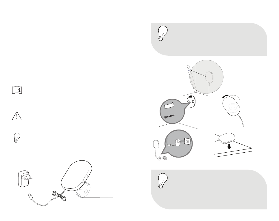
gateway
Power
Plug
LED light
Button
This guide is intended for Family Caregivers or Professionals
using the TENA SmartCareChange Indicator™/MC in a home
environment or a nursing home. The Change Indicator system
tracks and displays urine saturation levels in an absorbent
TENA incontinence product.
The TENA SmartCare Change Indicator is a system consisting of:
• an app, installed on one or more smartphones/handheld
devices.
• a reusable Change Indicator consisting of two parts;
a Sensor Strip and a Transmitter.
• a gateway that relays data from the Change Indicator.
Read the full TENA SmartCare Change Indicator
Instructions For Use before using the product.
REF
SN
IP65
FCC ID:
IC:
UDI:
MD
10
40
Symbols used in this guide:
WARNING
Care shall be taken to ensure safety and eiciency.
Failure to do so could cause damage to equipment
or lead to the receipt of incorrect data.
NOTE
Important information or advise/tip
REF
SN
IP65
FCC ID:
IC:
UDI:
MD
10
40
Parts you need to set-up gateway:
CLICK!
Screws or
adhesive tape
10 m (33 ft)
x2
or
Placement
CLICK!
Screws or
adhesive tape
10 m (33 ft)
x2
or
1
3Alternative
placement
NOTE
The gateway should be within 10 m (33 ft) of
the user and connected to an electric power
outlet to use the TENA SmartCare Change
Indicator System.
REF
SN
IP65
FCC ID:
IC:
UDI:
MD
10
40
NOTE
• If an internet connection cannot be established
please try to change location of the TENA
SmartCare gateway.
• It is preferred that the gateway is placed so it
has clear line of sight towards the Transmitter.
REF
SN
IP65
FCC ID:
IC:
UDI:
MD
10
40
2
CLICK!
Screws or
adhesive tape
10 m (33 ft)
x2
or
CLICK!
Screws or
adhesive tape
10 m (33 ft)
x2
or
4
5
Gateway installation
After attaching the gateway to a power outlet.
NOTE
The LED light can be diicult to see if it is
exposed to e.g. strong sunlight. Try to cover
the sunlight to improve readability.
REF
SN
IP65
FCC ID:
IC:
UDI:
MD
10
40
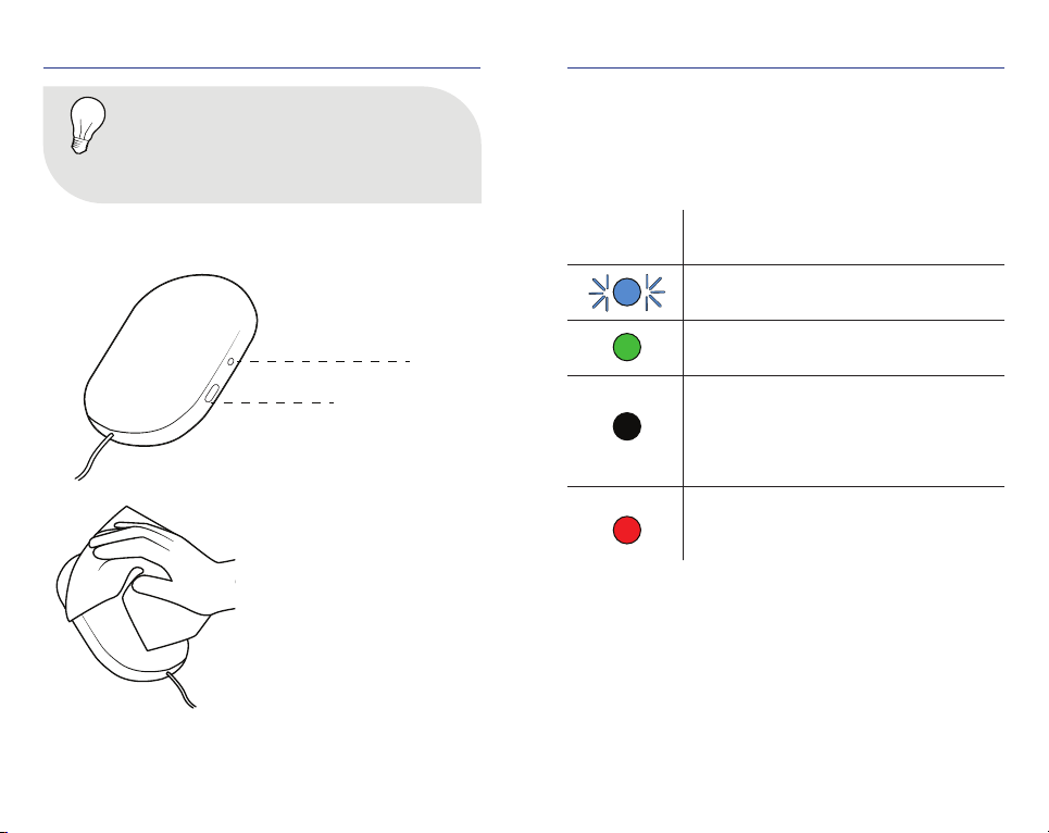
LED light
Button
Clean the gateway with a
dry cloth when needed.
Colour
LED light What it means
Blinking blue light:
Wait. The system is connecting.
Steady green light:
All is OK.
No light:
Green light disappears after a while and the
system goes into dark mode. Push the button
to see if it has power and connection. If no
light goes on, check the power connection.
Steady red light:
Error. See Troubleshoot section, p. 8-9,
in this guide for more information.
LIGHTS & BUTTONS & CLEANING LIGHTS & BUTTONS & CLEANING
6
7
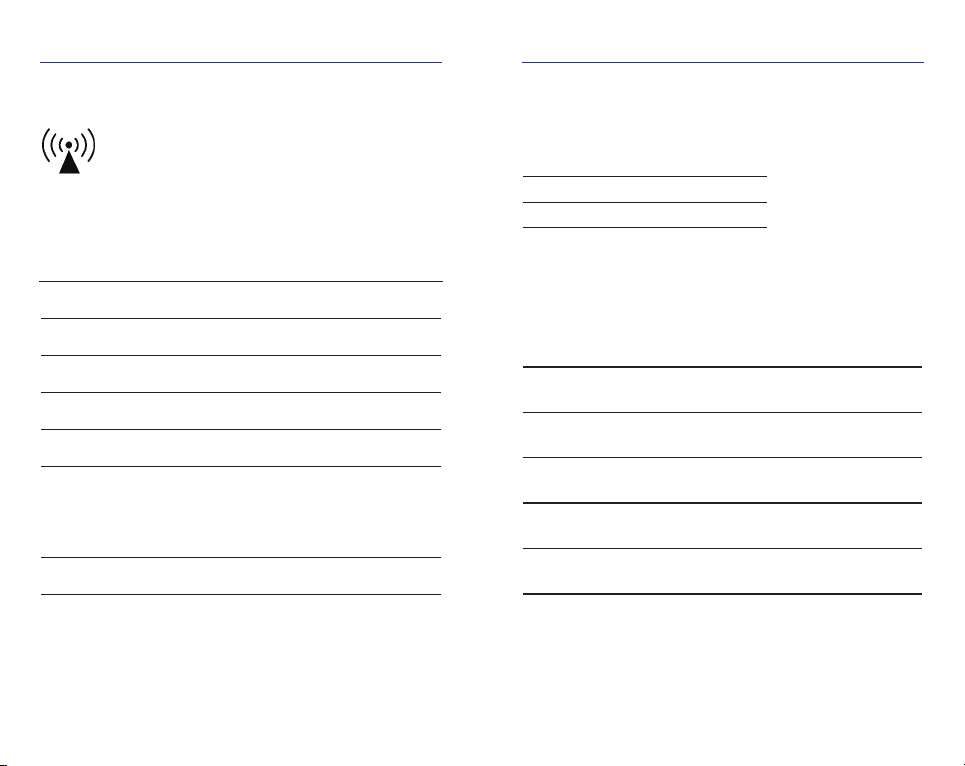
Type of communication BLE, LTE-M, 2 G
Frequency BLE 2.4 GHz
Peak Power 10 Watt
Average Power 0.7 Watt
Input Voltage 5 V
RF communications equipment (including peripherals
such as antenna cables and external antennas) should
be used no closer than 30 cm (12”) to the Change
Indicator. Otherwise, degradation of the performance
of this equipment could result.
Interference may occur in the vicinity of equipment
marked with this symbol.
REF
SN
IP65
FCC ID:
IC:
UDI:
MD
10
40
Product component dimensions (mm/ inch)
ITEM LENGTH WIDTH HEIGHT
Gateway 134 mm/ 5.28” 86 mm/ 3.39” 25 mm/ 0.98”
CONDITION MINIMUM MAXIMUM
Storage & transport temp. +10°C / 50°F +40°C / 104°F
Storage & transport humidity 65% Rh 90% Rh
Operating temp. +15°C / 59°F +45°C / 113°F
Operating humidity
(non-condensing) 15% Rh 90% Rh
Pressure 700 hPa 1060 hPa
Environmental conditions
Product weight (g/ ounce)
COMPONTENT WEIGHT
Gateway 174 g/ 6.14 oz
Mounting bracket 7 g/ 0.25 oz
TECHNICAL SPECIFICATION TECHNICAL SPECIFICATION

8
9
PROBLEM RESOLUTION
What is “Dark mode”?
The gateway LED light turns itself
o after a few seconds = goes into
dark mode in order to avoid distur-
bance during night. Press the button
to wake up the gateway again. If
nothing happens at a button-push,
please make sure the gateway is
connected to a power outlet.
There is something
wrong with the
connection to the
TENA SmartCare
Change Indicator
system.
• There may be no battery in
the transmitter or it is not
properly inserted. Please install
the battery and check the
installation.
• The transmitter may not be
correctly attached to the Sensor
Strip. Please check, and try again.
• The Transmitter code may be
wrong. Please check and try to
enter it again.
• The Transmitter may be to far
away from the gateway. Please
try to move the transmitter
closer to the gateway, within
10 m (33ft).
If it still does not work, please
contact TENA SmartCare support.
PROBLEM RESOLUTION
There is something
wrong with the gateway
connection.
• There is no power connection.
Please try to connect to another
power outlet.
• Push the button once. If there is
a green light it is OK. (It blinks
blue during setup.) If there is a
red light it is something wrong.
Please contact TENA SmartCare
support.
• Please try to take out the power
cord and replace it.
• Please try to move the gateway
to another location, maybe there
is no coverage in your location.
• Please contact your TENA Smart-
Care support if your gateway isn’t
activa ted in your warehouse - to
remote activation.
If it still does not work, please
contact TENA SmartCare support.
TROUBLESHOOT TROUBLESHOOT

10
11
IMPORTANT INFORMATION
• The gateway should not be sterilized.
• The gateway should not be used in an oxygen rich
environment.
• The gateway should not be used in presence of
ammable anaesthetics.
• Do not attempt to repair the gateway by yourself.
• Only use the power supply provided with the gateway.
• If the gateway connection cannot be established
it will not be able to send information and work as
expected. In such a case, please revert to a manual
process for checking the incontinence product. Check
the Troubleshooting section in this guide and if needed,
contact TENA SmartCare support.
• Do not open or modify the gateway. Doing so will result
in a void of warranty and can result in an unidentied
risk to patient, operator or third party.
• Changes or modications not expressly approved by
the party responsible for compliance could void the
user’s authority to operate the equipment.
• Save this user manual for future reference.
• If any changes to the installation are necessary, please
contact TENA SmartCare support.
• Devices shown are not actual size.
This device complies with part 15 of the FCC Rules. Operation is
subject to the following two conditions: (1) This device may not
cause harmful interference, and (2) this device must accept any
interference received, including interference that may cause
undesired operation.
NOTE:
This equipment has been tested and found to comply with the
limits for a Class B digital device, pursuant to part 15 of the FCC
Rules. These limits are designed to provide reasonable protec-
tion against harmful interference in a residential installation.
This equipment generates, uses and can radiate radio frequency
energy and, if not installed and used in accordance with the in-
structions, may cause harmful interference to radio communica-
tions. However, there is no guarantee that interference will not
occur in a particular installation. If this equipment does cause
harmful interference to radio or television reception, which can
be determined by turning the equipment o and on, the user is
encouraged to try to correct the interference by one or more of
the following measures:
• Reorient or relocate the receiving antenna.
• Increase the separation between the equipment and receiver.
• Connect the equipment into an outlet on a circuit dierent
from that to which the receiver is connected.
• Consult the dealer or an experienced radio/TV technician
for help.
WARNINGS IMPORTANT INFORMATION

12
13
This equipment complies with the ICES RF radiation exposure
limits set forth for an uncontrolled environment. This equipment
should be installed and operated with a minimum distance of
20cm between the radiator and any part of the human body.
Cet équipement est conforme aux limites d’exposition aux
radiations ICES dénies pour un environnement non contrôlé .
Cet équipement doit être installé et utilisé à une distance
minimale de 20 cm entre le radiateur et une partie de votre
corps.
This device contains licence-exempt transmitter(s)/receiver(s)
that comply with Innovation, Science and Economic Development
Canada’s licence-exempt RSS(s). Operation is subject to the
following two conditions:
• This device may not cause interference.
• This device must accept any interference, including interfer-
ence that may cause undesired operation of the device.
Le présent appareil est conforme aux CNR d’Industrie Canada
applicables aux appareils radio exempts de licence. L’exploitation
est autorisée aux deux conditions suivantes : (1) l’appareil ne
doit pas produire de brouillage, et (2) l’utilisateur de l’appareil
doit accepter tout brouillage radioélectrique subi, même si le
brouillage est susceptible d’en compromettre le fonctionnement.
WARNINGS IMPORTANT INFORMATION

14
15
LABELLING SYMBOLS
The following symbols appear on your TENA SmartCare
gateway or accessories and/or packaging:
REF
SN
IP65
FCC ID:
IC:
UDI:
MD
10
40
WEEE-marking.
Dispose of electrical components in
accordance with your local regulations.
REF
SN
IP65
FCC ID:
IC:
UDI:
MD
10
40
European Conformity mark
Radio Frequency Radiation Symbol
REF
SN
IP65
FCC ID:
IC:
UDI:
MD
10
40
Instruction manual
Storage- and transport temperarture
Humidity limitation
Atmospheric pressure limitation
65 % Rh
90 % Rh
700 hPa
1060 hPa

TENA
an Essity brand
91285
REF
SN
IP65
FCC ID:
IC:
UDI:
MD
10
40
FCC ID: 2ABIC3-91285 IC: 10866A-91285
Contains FCC ID: N7NWP77B Contains IC: 2417C-WP77B
Manufactured by: Essity Hygiene and Health AB
SE-405 03 Göteborg, Sweden
Visiting address: Mölndals Bro 2, Mölndal
Distributed in the US by: Essity HMS North America Inc.
Distributed in Canada by: Essity Canada Inc.
Cira Centre, 2929 Arch Street, Suite 2600.
Philadelphia, PA 19104
Made in Sweden www.essity.com
REF
SN
IP65
FCC ID:
IC:
UDI:
MD
10
40
Version: NA 2020-08-20
Table of contents
Other TENA Gateway manuals

Popular Gateway manuals by other brands


Rolls
Rolls LFP Connect Card user manual

THOMSON
THOMSON TG508 Setup and user guide

Pathway connectivity solutions
Pathway connectivity solutions Pathport OCT user guide

AudioCodes
AudioCodes MediaPack 114 Configuration guide

Cisco
Cisco Meraki Z3C installation guide

ZyXEL Communications
ZyXEL Communications ZyXEL ZyWALL USG-1000 Support notes

AudioCodes
AudioCodes Mediant 1000 user manual

Comcast
Comcast machineQ mQHub user guide

Lucent Technologies
Lucent Technologies PacketStar PSAX Brochure & specs

XAVI Technologies Corp.
XAVI Technologies Corp. X7968r user manual

ZyXEL Communications
ZyXEL Communications UAG4100 Application note

Volansys
Volansys Modular IoT Gateway Hardware user's guide