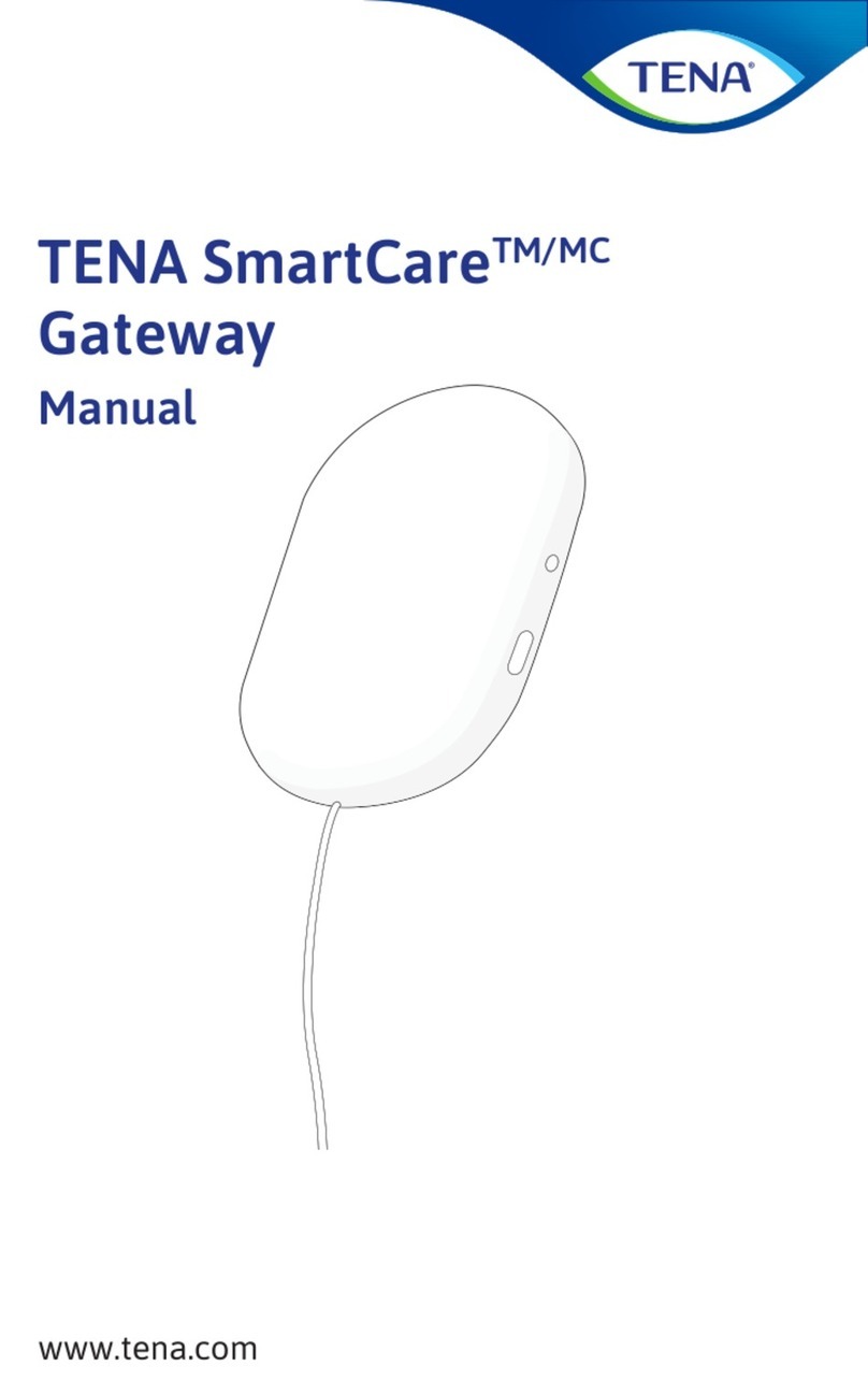
TENA SmartCare Gateway User manual

EN TENA SmartCareTM gateway manual p. 2
ES TENA SmartCareTM manual de uso del receptor p. 14
FR TENA SmartCareMC passerelle manuel p. 26
Manual
TENA SmartCareTM/MC
Gateway
EN, ES, FR

2
EN INFORMATION
This guide is intended for family caregivers or professional
caregivers using the TENA SmartCare Change IndicatorTM/MC
inahome environment or a care home. The Change Indicator
system tracks and displays urine saturation levels in TENA
incontinence products.
TENA SmartCare Change Indicator is a system consisting of:
• an app installed on one or more smartphones/handheld
devices,
• a reusable Change Indicator made up of two parts:
a sensor strip and a transmitter,
• a gateway that relays data.
Symbols used in this guide:
WARNING
Care shall be taken to ensure safety and eiciency.
Failure to do so could cause damage to equipment
or lead to the receipt of incorrect data.
NOTE
Important information or advice/tip.
MOUNTING
BRACKET
GATEWAY
POWER
ADAPTER
Button
LED light
Parts you need to set up the gateway:
Read the full TENA SmartCare Change Indicator
instructions for use before using the system.

3
Steady light
= connected
Blinking light
= connecting
No light
= OK
1
3
2
4
GATEWAY SETUP
EN
NOTE
The gateway should be within 33 ft (10 m) from
the Change Indicator and plugged into a power
socket to use the TENA SmartCare Change
Indicator system.
Placement
Click!
33 ft (10 m)
Light
NOTE
• If an internet connection cannot be established,
please try to change the location of the TENA
SmartCare gateway.
• It is advised for the gateway to be placed so
thatis has a clear line of sight towards the
ChangeIndicator.
You can also place the gateway
on a at surface
Screws or
adhesive strip

4
NOTE
The LED light can be diicult to see if it is
exposedtostrong sunlight, for example. Try
blockingthe sunlight to improve readability.
Button
LED light
EN LIGHTS, BUTTONS, CLEANING
Clean the gateway with
a dry cloth when needed

5
Gateway installation
Plug the gateway into a power socket.
LIGHTS, BUTTONS, CLEANING
EN
Color
LED light What it means
Blinking blue light:
Wait. The system is connecting. Allow up to
60 seconds for the LED light to start blinking.
Steady green light:
All is OK. Allow up to 60 seconds for the LED
light to turn green.
No light:
Green light disappears after a while, and
the system goes into dark mode. Push the
button to see if it has power and network
connection. If no light comes on, check the
power connection.
Steady red light:
Error. See the troubleshooting section on
pp. 8–9 of this guide for more information.

6
EN TECHNICAL SPECIFICATIONS
RF communications equipment (including peripherals
such as antenna cables and external antennas)
should be used no closer than 12" (30 cm) to the
Change Indicator. Otherwise, it could result in
degradation of the performance of this equipment.
Interference may occur in the vicinity of equipment
marked with this symbol.
Type of communication BLE, LTE-M, 2 G
Frequency BLE 2.4 GHz
Peak Power 10 Watts
Average Power 0.7 Watts
Input Voltage 5 V
Product component dimensions (mm/ inches)
ITEM LENGTH WIDTH HEIGHT
Gateway 134 mm/ 5.28" 86 mm/ 3.39" 25 mm/ 0.98"

7
TECHNICAL SPECIFICATIONS
EN
Product weight (g/ ounces)
COMPONENT WEIGHT
Gateway 174 g/ 6.14 oz
Mounting bracket 7 g/ 0.25 oz
CONDITION MINIMUM MAXIMUM
Storage & transport
temperature +10°C/ 50°F +40°C/ 104°F
Storage & transport humidity 65% Rh 90% Rh
Operating temperature +15°C/ 59°F +40°C/ 104°F
Operating humidity
(non-condensing) 15% Rh 90% Rh
Atmospheric pressure 700 hPa 1060 hPa
Environmental conditions

8
PROBLEM RESOLUTION
Connection error
(gateway)
1. Check the power supply, are the
power cable and power adapter
both connected properly?
2. If there is a blinking blue light,
the gateway is trying to connect.
3. If the gateway does not connect
after one minute, try moving it
to a place in the room where the
network connection is stronger.
4. Occasionally, the cellular
network may go down. If this
happens, revert to a manual
changing routine until the system
is up and running again.
If it still does not work, please
contact TENA SmartCare support.
EN TROUBLESHOOTING

9
PROBLEM RESOLUTION
Connection error
(Change Indicator)
1. Check if the transmitter battery
is installed properly.
2. Check if the transmitter is
properly attached to the
sensorstrip.
3. Check that you have registered
the correct transmitter code.
4. Try moving the gateway closer
to the Change Indicator, within
33 ft (10 m).
If it still does not work, please
contact TENA SmartCare support.
TROUBLESHOOTING
EN

10
IMPORTANT INFORMATION
• The gateway should not be sterilized.
• The gateway should not be used in an oxygen-rich
environment.
• The gateway should not be used near ammable anesthetics.
• Do not attempt to repair the gateway by yourself.
• Only use the power supply provided with the gateway.
• If the gateway connection cannot be established, it will not
beable to send information and work as expected. Insuch
a case, please revert to a manual process for checking
incontinence products.
• Do not open or modify the gateway.
• Changes or modications not expressly approved by the party
responsible for compliance, could void the user’s authority to
operate the equipment.
• Save this user manual for future reference.
• If any changes to the installation are necessary, please
contact TENA SmartCare support.
• Devices shown are not in actual size.
• The adhesive strip will not adhere well to dirty, dusty or oily
surfaces and may not adhere well to vinyl surfaces. Do not use
the adhesive strip on wallpaper, bare wood or on porous and
painted surfaces.
EN WARNINGS

11
IMPORTANT INFORMATION
EN
This device complies with part 15 of the FCC Rules. Operation is subject to the
following two conditions: (1) this device may not cause harmful interference and,
(2) this device must accept any interference received, including interference that
may cause undesired operation.
NOTE:
This equipment has been tested and found to comply with the limits for a Class B
digital device, pursuant to part 15 of the FCC Rules. These limits are designed to
provide reasonable protection against harmful interference in a residential
installation. This equipment generates, uses and can radiate radio frequency
energy and, if not installed and used in accordance with the instructions, may cause
harmful interference to radio communications. However, there is no guarantee
that interference will not occur in a particular installation. If this equipment does
not cause harmful interference to radio or television reception, which can be
determined by turning the equipment o and on, the user is encouraged to try
to correct the interference with one or more of the following measures:
• Reorient or relocate the receiving antenna.
• Increase the separation between the equipment and receiver.
• Connect the equipment into an outlet no a circuit dierent from that to
which the receiver is connected.
• Consult the dealer or an experienced radio/TV technician for help.
This device contains license-exempt transmitter(s)/ receiver(s) that comply
withInnovation, Science and Economic Development Canada’s license-exempt
RSS(s). Operation is subject to the following two conditions: (1) this device may
not cause interference and, (2) this device must accept any interference,
including interference that may cause undesired operation of the device.
Le présent appareil est conforme aux CNR d’Industrie Canada applicables aux
appareils radio exempts de licence. L’exploitation est autorisée aux deux
conditions suivantes : (1) l’appareil ne doit pas produire de brouillage, et (2)
l’utilisateur de l’appareil doit accepter tout brouillage radioélectrique subi,
même si le brouillage est susceptible d’en compromettre le fonctionnement.
This equipment complies with the ICES RF radiation exposure limits set forth
for an uncontrolled environment. This equipment should be installed and
operated at a minimum distance of about 8”/ 20 cm between the radiator and
any part of the human body.
Cet équipement est conforme aux limites d’exposition aux radiations ICES
dénies pour un environnement non contrôlé . Cet équipement doit être installé
et utilisé à une distance minimale de 8”/ 20 cm entre le radiateur et une partie
de votre corps.

12
WEEE mark
Dispose of electrical components
in accordance with your local regulations
European Conformity mark
Radio Frequency Radiation symbol
Instructions for use
Storage & transport temperature
10 °C
50 °F
40 °C
104 °F
Atmospheric pressure limitation
Humidity limitation
90% Rh
65% Rh
1060hPa
700hPa
The following symbols may appear on your TENA SmartCare
gateway or accessories and/or packaging:
EN LABELING SYMBOLS

Manufactured by: Essity Hygiene and Health AB
SE-405 03 Göteborg, Sweden
Visiting address: Mölndals bro 2, Mölndal
Distributed in the U.S. and Canada by:
Essity HMS North America Inc.
Cira Centre, 2929 Arch Street, Suite 2600
Philadelphia, PA 19104
Support phone number: 1-866-335-4735
www.tena.us www.tena.ca
Made in Sweden
91290
IC: 10866A-91290
Contains IC: 2417C-WP77B
FCC ID: 2ABK3-91290
Contains FCC ID: N7NWP77B

14
ES INFORMACIÓN
La presente guía está dirigida a familiares cuidadores o
cuidadores profesionales que usan TENA SmartCareChange
IndicatorTM/MC en el entorno de un hogar o un centro asistencial. El
sistema de indicador para cambiar verica y muestra los niveles
de saturación de orina en los productos absorbentes TENA.
TENA SmartCare Change Indicator es un sistema que consta de
lo siguiente:
• una aplicación instalada en uno o más teléfonos inteligentes/
dispositivos manuales;
• un indicador para cambiar reutilizable de dos partes,
una tira sensora y un transmisor;
• un receptor que envía datos.
Símbolos que se usan en esta guía:
ADVERTENCIA
Se tomarán precauciones para garantizar la seguridad
yla eciencia. No hacerlo podría dañar el equipo
ohacer que se reciban datos incorrectos.
NOTA
Información o consejo importante.
SOPORTE DE
MONTAJE
RECEPTOR
ADAPTADOR
DE CORRIENTE
Botón
Luz LED
Componentes que se necesitan para instalar el receptor:
Lea las instrucciones de uso completas del TENA
SmartCare Change Indicator antes de usar el sistema.

15
Steady light
= connected
Blinking light
= connecting
No light
= OK
1
3
2
4
INSTALACIÓN DEL RECEPTOR ES
NOTA
El receptor debe estar a menos de 10 m (33 pies)
del indicador para cambiar y conectarse a un
tomacorriente para poder usar el sistema TENA
SmartCare Change Indicator.
Colocación
¡Haga clic!
10m (33pies)
Luz
NOTA
• Si no puede establecer la conexión a Internet,
intente cambiar la ubicación del receptor TENA
SmartCare.
• Se recomienda que el receptor se coloque en
un lugar con una línea de visión despejada al
indicador para cambiar.
El receptor también se puede
colocar sobre una supercie plana.
Componentes que se necesitan para instalar el receptor:
Tornillos o
tira adhesiva

16
NOTA
Puede que sea difícil ver la luz LED si está expuesta
a, por ejemplo, luz del sol intensa. Intente bloquear
la luz del sol para mejorar la legibilidad.
Botón
Luz LED
ES LUCES, BOTONES, LIMPIEZA
Limpie el receptor con
unpaño seco cuando
seanecesario.

17
Instalación del receptor
Enchufe el receptor
LUCES, BOTONES, LIMPIEZA ES
Color de la
luz LED Signicado
Luz azul intermitente:
Espere. El sistema se está conectando. Espere
hasta 60segundos para que la luz LED
comience a parpadear.
Luz verde ja:
Todo está bien. Espere hasta 60segundos
para que la luz LED se ponga verde.
Sin luz:
La luz verde desaparece después de un
tiempo y el sistema pasa a modo oscuro.
Pulse el botón para determinar si tiene
conexión eléctrica y a Internet. Si la luz no se
enciende, verique la conexión eléctrica.
Luz roja ja:
Error. Para obtener más información, consulte
la sección de resolución de problemas en las
págs.20 y 21 de la presenteguía.

18
ES ESPECIFICACIONES TÉCNICAS
Los equipos de comunicaciones por radiofrecuencia
(entre ellos los periféricos, como los cables de
antena y las antenas externas) no deben usarse
amenos de 30cm (12”) del indicador para cambiar.
Delo contrario, eso podría provocar la degradación
del rendimiento de este equipo.
Puede haber interferencia en las cercanías de
cualquier equipo marcado con este símbolo.
Tipo de comunicación BLE, LTE-M, 2 G
Frecuencia BLE 2.4GHz
Potencia máx. 10vatios
Potencia promedio 0.7vatios
Tensión de entrada 5V
Dimensiones de los componentes del producto (mm/ pulg.)
ARTÍCULO LONGITUD ANCHO ALTURA
Receptor 134mm/ 5.28" 86mm/ 3.39" 25mm/ 0.98"

19
ESPECIFICACIONES TÉCNICAS ES
Peso del producto (g/ onzas)
COMPONENTE PESO
Receptor 174g/ 6.14oz
Soporte de montaje 7g/ 0.25oz
CONDICIÓN MÍNIMA MÁXIMA
Temp. de transporte y
almacenamiento +10°C/ 50°F +40°C/ 104°F
Humedad de transporte y
almacenamiento 65% HR 90% HR
Temp. funcionamiento +15°C/ 59°F +40°C/ 104°F
Humedad durante el
funcionamiento(sin condensación) 15% HR 90% HR
Presión atmosférica 700hPa 1060hPa
Condiciones ambientales

20
PROBLEMA SOLUCIÓN
Error en la conexión
(receptor)
1. Verique la fuente de
alimentación. ¿Tanto el cable de
alimentación como el adaptador
de corriente están correctamente
conectados?
2. Si la luz del receptor es azul
eintermitente, el receptor está
intentando conectarse.
3. Si pasado un minuto el receptor
no se conecta, intente moverlo
aun lugar de la habitación con
una mejor conexión a la red.
4. Ocasionalmente, es posible que la
red móvil se caiga. Si eso sucede,
use una rutina de cambio manual
hasta que el sistema vuelva a
estar activo y en funcionamiento.
Si aún no funciona, comuníquese
con el soporte técnico de TENA
SmartCare.
ES RESOLUCIÓN DE PROBLEMAS
Other manuals for SmartCare Gateway
1
This manual suits for next models
1
Table of contents
Languages:
Other TENA Gateway manuals
Popular Gateway manuals by other brands

Siemens
Siemens 5WG1 141-1AB31 Operating and mounting instructions

Cisco
Cisco VG420 Installing

TEKTELIC Communications
TEKTELIC Communications Kona Mega Gateway quick start guide

ZyXEL Communications
ZyXEL Communications ZyXEL ZyWALL 5 user guide

RTA
RTA 460PSDM-N34 Product user guide

ZyXEL Communications
ZyXEL Communications P-793H 601156 user guide