TenaControls CARL-BB User manual

Ten^Controls LLC Milford, M@ 01757 US@ www.ten^controls.com
Ten^Controls Brings Models to Life
© Cop right 2013 Ten^Controls LLC P^ge 1
Instructions for Model#: CARL-BB, the Standard Car Lighting
System for 1 25 Scale Model Cars
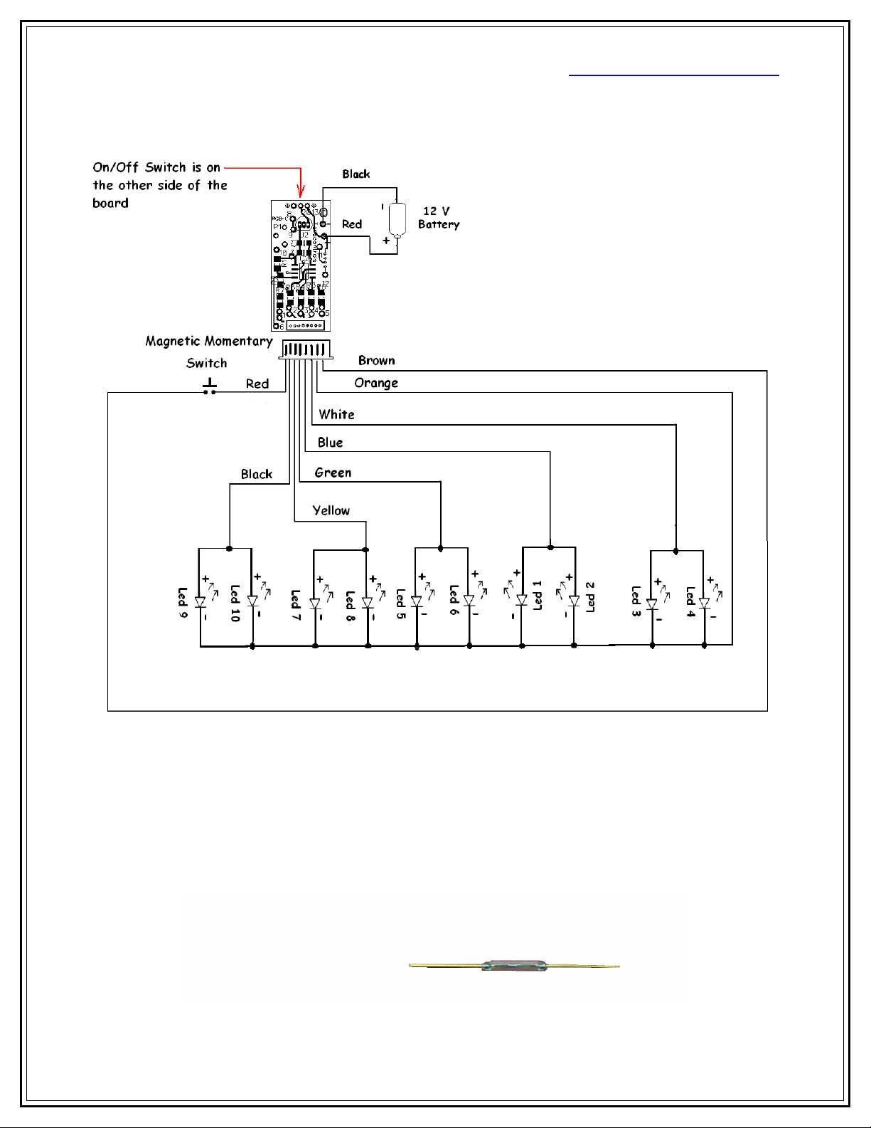
This unit is completely assembled and tested. The only thing you need to do is connect
up the led’s and the Momentary Magnetic Switch to the connection points as shown
below in the Master Wiring Diagram. Then just plug in the provided 12 volt battery into
the holder and throw the micro slide switch on. Hot glue drops on the four sides of the
board works well for locking into place.
Items you will need: Soldering Iron, solder, cutter, wire stripper and additional wiring.
**Note: When using the shrink tubing, you need to only slide the shrink tubing over one
leg of the led to keep it from shorting against the other leg. Then use heat gun or flame
from lighter to heat the shrink tubing until it shrinks around the wire connected to one
of the led legs.
How to distinguish a led:
Anode Side (+) Cathode Side (-)
Ten^Controls LLC Milford, M@ 01757 US@ www.ten^controls.com
Ten^Controls Brings Models to Life
© Cop right 2013 Ten^Controls LLC P^ge 2
Picture of magnetic switch

Ten^Controls LLC Milford, M@ 01757 US@ www.ten^controls.com
Ten^Controls Brings Models to Life
© Cop right 2013 Ten^Controls LLC P^ge 3
Rear Back Up Lights
1. Two White led’s, LED1-LED . The Two Anodes (+) of the Rear Back up Lights
led’s, LED1-LED2 connect to the Blue wire from the pc board. Then connect the
Cathode (-) of LED1-LED2 to the Orange wire from the pc board. See above
diagram.
Rear Driving Lights
2. Two Red led’s, LED3-LED4. The Two Anodes (+) of the Rear Driving Lights led’s,
LED3-LED4 connect to the White wire from the pc board. Then connect the
Cathode (-) of LED3-LED4 to the Orange wire from the pc board. See above
diagram.
Front Driving Lights
3. Two White LED5-LED6. The Two Anodes (+) of the Front Driving Lights led’s,
LED5-LED6 connect to the Green wire from the pc board. Then connect the
Cathode (-) of LED5-LED6 to the Orange wire from the pc board. See above
diagram.
Right Side Front & Rear Directional Lights
4. Two Orange LED7-LED8. The Two Anodes (+) of the Right Side Front and Rear
Directional Lights led’s, LED7-LED8 connect to the Yellow wire from the pc
board. Then connect the Cathode (-) of LED7-LED8 to the Orange wire from the
pc board. See above diagram.

Ten^Controls LLC Milford, M@ 01757 US@ www.ten^controls.com
Ten^Controls Brings Models to Life
© Cop right 2013 Ten^Controls LLC P^ge 4
Left Side Front & Rear Directional Lights
5. Two Orange LED9-LED10. The Two Anodes (+) of the Left Side Front and Rear
Directional Lights led’s, LED9-LED10 connect to the Black wire from the pc
board. Then connect the Cathode (-) of LED9-LED10 to the Orange wire from the
pc board. See above diagram.
6. Once all the above wiring is done and the Magnetic Switch is mounted in the area
of your choice. Slide the power on Switch to the on position, the front and rear
driving lights will come on. The first Swipe using the enclosed magnet across the
Magnetic Switch will turn the High Beams “on”. The second Swipe across the
Magnetic Switch will turn the Left Front and Rear Directional “on”. The third
Swipe across the Magnetic Switch will turn the Right Front and Rear Directional
“on”. The fourth Swipe across the Magnetic Switch will turn the Rear Brake
Lights “on”. The fifth Swipe across the Magnetic Switch will turn the Rear Back
up Lights “on”. The sixth Swipe across the Magnetic Switch will turn all four
directional Lights “on” to simulate Hazard lights. The seventh Swipe across the
Magnetic Switch will place the car lighting system on automatic sequencing
through all the above lighting phases. To return to manual mode just swipe across
the Magnetic Switch one more time.

Ten^Controls LLC Milford, M@ 01757 US@ www.ten^controls.com
Ten^Controls Brings Models to Life
© Cop right 2013 Ten^Controls LLC P^ge 5
Warranty
TenaControls warrants that the control boards sold meet TenaControls
specifications and are adequately contained, packaged and labeled and conform to the
promises and affirmations of fact made on the container and label. THE FOREGOING
WARRANTIES ARE EXCLUSIVE, AND ARE IN LIEU OF ALL OTHER WARRANTIES
(WHETHER WRITTEN, ORAL OR IMPLIED) INCLUDING WARRANTY OR
MERCHANTABILITY IN OTHER RESPECTS THAN EXPRESSLY SET FORTH ABOVE
AND WARRANTY OF FITNESS FOR A PARTICULAR PURPOSE.
In the event that there is a breach of express warranty by the manufacturer
made in connection with the purchase of this product, if any, the sole remedy of any
buyer shall be to return the product along with original sales receipt, at buyer’s
expense for repair (or replacement of the product if repair is impossible) to the
manufacturer’s facility in the Commonwealth of Massachusetts, located at 22 Hancock
Street, Milford, MA 01757. Some states do not allow the exclusion or limitation of any
incidental or consequential damages, so the above limitation may not apply to you.
Nothing herein contained shall be construed to be a waiver by the manufacturer of any
of the obligations imposed upon said buyer under the laws of the Commonwealth of
Massachusetts except as herein specifically stated.
This warranty is enforceable only by the buyer of the product or a person in the
buyer’s immediate family. This warranty is enforceable for a period of FIVE YEARS
from the date of purchase. Some states do not allow limitations on how long an implied
warranty lasts, so the above warranty may not apply to you. This warranty gives you
specific legal rights and you may also have other rights which vary from state to state.
Warranty Void if:
A) Product is altered in any way.
B) Used for other than its intended use.
C) Buyer mishandling.
Table of contents
Other TenaControls Light Fixture manuals

Popular Light Fixture manuals by other brands


Lightolier
Lightolier Calculite ProSpec PB4H3870 specification

Energetic Lighting
Energetic Lighting MXL2048-LED40K8040 installation instructions

Trilux
Trilux Oktalite IN.VOLA installation instructions

Audibax
Audibax Monster 200 Hybrid user manual

TECshow
TECshow NEBULA FX 3-in-1 user manual

Sound Sation
Sound Sation Twilight 60 ENDLESS user manual