Tensai TR-1030 User manual

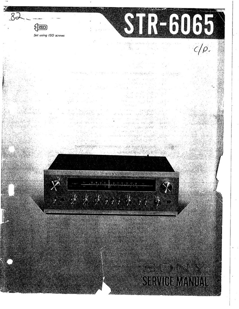
SERVICE
MANUAL
TENSAI
INTERNATIONAL
HI-Fl
STEREO
RECEIVER
MODEL
TR-
1030

CONTENTS
SPECIFICATIONS
GENERAL
TROUBLESHOOTING
CHART
DIAL
CORD
STRINGING
FM
ALIGNMENT
PROCEDURE
AM
ALIGNMENT
PROCEDURE
PROTECTION
CIRCUIT
TRANSISTOR
VIEW
DESCRIPTION
OF
EXPLODED
EXPLODED
VIEW
SCHEMATIC
DIAGRAM
BLOCK
DIAGRAM
P.C.
BORD
AND
PARTS
LIST
OADum
fw FP
RWWHNOD
—
“w
9.10.11.12
a
;
if
i
i
:
H
i
ial
eet
ce
eas
ere
dah:
SE:
Se
ee
eee
or
:

SPECIFICATIONS
Amplifier
section
Continuous
power
output
at
1KHz
both
channels
driven
T.H.D.
at
1W
at
rated
output
Power
bandwidth
Frequency
response
Damping
factor
Input
sensitivty
Cross
talk
S/N
ratio
(Unweighted)
Input
overload
Tone
control
Loudness
Filter
Program
AM,
FM,
MPX
AM
reception
a
sea
|
_
FM
section
4
ohms
2x35W
'
Useable
sensitivity
1.6UV
8
ohms
2x
25W
Tuning
range
87.5—109MHz
oY
:
T.H.D.
Mono
0.2%
eee
ae
Stereo
0.4%
S/N
ratio
Mono
60dB
10-50000
Hz
Stereo
55dB
50
Image
rejection
80dB
Phono
2.5mV
1.F.
rejection
90dB
Mic
2.5mV
AM
suppression
55dB
Aux
160mV
Intermodulation
80dB
Tape
160mV
Spurious
response
80dB
1KHz
60dB
Muting
level
SUV
10KHz
40dB
Frequency
response
20—15000Hz
.
Phono
70dB
19
KHz
rejection
50dB
Mic
65dB
38
KHz
rejection
60dB
Aux
85dB
Stereo
separation
45dB
120mV
fee
AM
section
nate
+10d8
Tuning
range
MW
:
525—1650
KHz
baer
eae
fe
LW
:
130—365
KHz
aie
nn
Useable
sensitivity
a
Zn
Low
708
T.H.D.
MW
:
ca
|
LW
:15
%
S/N
ration
MW
:
45dB
LW
:
40d8
1.F.
rejection
MW
:
40dB
,
LW
:
30dB
AGC
figure
of
merit
MW
:
60dB
LW
:
60dB
Frequency
response
MW
:
100—2500Hz
GENERAL
TROUBLESHOOTING
CHART
If
the
set
is
otherwise
operating
satisfactorily,
the
more
common
causes
of
trouble
may
be
generally
attributed
to
the
following:
1.
2.
Incorrect
connections
or
loose
terminal
contact
player,
tape
recorder,
antenna
and
line
cord.
Improper
operation.
Before
operating
any
au
instructions.
LW
:
100—2500Hz
5s,
Check
the
connections
of
speaker,
record
dio
component,
be
sure
to
read
the
manufacturer’s
Improper
location
of
audio
components.
The
proper
positioning
of
components,
such
as
speakers
and
turntable,
_
Defective
audio
components.
and
what
to
do
about
them.
Symption
4.
Constant
or
intermittent
noise
heard
at
times
Or
in
a
certain
area
2.
The
needle
of
the
signal
and
tuning
meter
does
not
move
sharply
3.
The
zero
point
of
the
meter
diverges
much
1.Noise
heard
at
a
particular
time
of
a
day
in
a
certain
area
of
any
part
of
dial
2.
High-frequency
noise
3.
Broadcasting
interference
is
vital
to
stereo.
The
followings
are
some
other
common
causes
of
mainfunction
Probable
Cause
1.Discharge
or
oscillation
caused
by
electrical
appliances,
such
as
flourescent
jamp,
TV
set,
D.C.
motor
rectifier
or
Oscillator
2.Natural
phenomena
such
as
atmospheric
static
or
thunderbolts
3.Insufficient
antenna
input
due
to
ferroconcrete
wall
or
long
distance
from
the
station
4.Wave
interference
from
other
electrical
appliances
1.The
set
is
located
in
a
weak
signal
area
2.Some
FM
or
TV
broadcasting
station
is
near
at
hand
1.Regional
difference
in
field
intensity
1.Due
to
the
nature
of
AM
broadcasts
1.
Adjacent
channel
interference
or
beat
interference
2.TV
set
tog
close
to
audio
system
1.Antenna’s
input
sensitivity
is
too
strong
What
to
do
1.Attach
a
noise
limiter
to
the
electrical
appliances
causing
the
noise,
or
attach
it
to
the
amplifiers
power
sources
2.{nstall
an
outdoor
antenna
and
ground
the
set
to
raise
the
signal-to-noise
ratio
3.Reverse
the
power
cord
plug
receptacle
connections
4.1f
the
noise
occurs
at
a
certain
frequency,
attach
a
wave
trap
to
the
antenna
input
5.Keep
the
set
at
a
proper
distance
from
other
electrical
appliances
1.Place
the
set
to
receive
maximum
signal
strength
2.Ground
the
set
to
the
earth
1.The
unit
is
not
at
fault
a
1.In
some
cases,
the
noise
can
be
eliminated
by
grounding
the
set
or
reversing
the
power
cord
plug-receptacie
connections
1.Although
such
noise
cannot
be
eliminated
by
the
set,
it
is
advisable
to
adjust
the
TREBLE
control
from
midpoint
to
left
and
switch
on
the
HIGH
FILTER
2.Keep
the
TV
set
at
a
proper
distance
from
the
audio
system
1.Connect
resistor
(1K-10K)
in
series
to
antenna
terminal.
wohl
=
ht
ete
a
ee
eg
ee
Se
Se
eee
roams
itiege
SHE
SH
SRA
IAL
Sees.
Chet
S833
SLO
SS
SB
UR
EDIE
hl
SSE
SES
AG
IS
TEST
SSG
BTEM
SSS
SE
EEA
ESR
ALAA
DAE
ERE
AENEAN
SEE
IEEE
IEEE
ERG
TAB
AEEN
GREE
EEGAEEEE
EENE
LRS
EER
LOTE
ABBE
EDIE
SLES
BLE
REIT

4
sb
2
one
MeN
Probable
Cause
What
to
do
Program
Symptom
EM
1.Noisy
-1.Poor
noise
limiting
effect
or
too
1.Install
the
antenna
for
maximum
signal
reception
low
S/N
ratio
due
to
insufficient
strength
,
2.1f
this
does
not
prove
effective,
use
an
antenna
input
Sie
ee
a
en
ee
Outdoor
antenna
designed
exclusively
Note:
FM
reception
is\affected
considerably
by
trarismission
condition
of
station
power
and
antenna
efficiency.
As
a
result,
you
may
receive
one
station
quite
well
while
receiving
another
station
poorly
2.Noise
heard
like
scratch
3.
Tuning
noise
between
stations
FM/MPX
4.
Noise
heard
during
:
&M/MPxX
reception
while
not
heard
during
FM
mono
reception
2.Clearness
of
channel
separation
is
decreased
during
reception.
1.The
stereo
indicator
blinks
on
and
off
Record
4.
Hum
or
howling
playing
or
tape
playback
2.Surface
noise
All
stereo
BALANCE
control
is
not
at
programs
midpoint
when
equal
sou
nd
comes
from
left
and
right
>
channels
DIAL
CORD
STRINGING
1.1gnition
noise
caused
by
starting
of
an
automobile
engine
1.This
results
from
the
nature
of
the
FM
reception.
As
the
station
signal
becomes
weak,
the
noise
limiter
effect
is
decreased
and
the
amplification
of
the
limiter,
in
turn,
is
enlarged
generating
noise
©
1.Weaker
signal
because
the
service
area
of
the
FM/MPX
broadcast
is
only
half
that
of
the
FM
mono
broadcast
1.Excess
heat
of
IC
.
1.Interference
2.Too
weak
RF
signal
1.Record
player
placed
too
close
to
speaker
2.Wire
other
than
shielded
wire
used
3.Loose
terminal
contact
‘4.Shielded
wire
too
close
to
line
cord,
tlorescent
lamp
or
other
electrical
appliances
5.Nearby
amateur
radio
station
Or
TV
transmission
antenna
1.Worn
or
old
record
2.Worn
needle
3.Needle
dusty
4.Improper
needle
pressure
It
is
important
to
adjust
for
equal
sound
comes
from
both
channels.
It
should
not
always
be
set
to
the
midpoint
for
FM.
When
you
use
a
TV
antenna
for
both
TV
and
FM
with
a
divider,make
sure
TV
reception
is
not
affected
—3.An
exclusively
long
antenna
may
cause
noise
1.Install
the
antenna
and
its
lead-in
wire
in
proper
distance
from
the
road
or
raise
the
antenna
input
as
described
above
1.Turn
the
MUTING
switch
on.
It
reduces
the
sensitivity,
and
therefore
it
should
be
used
sparingly
1.Install
the
antenna
for
maximum
antenna
input
|
2.Switch
on
the
high
filter
and/or
turn
the
TREBLE
control
from
midpoint
to
left
~
4.Circulation
of
air
is
important
to
the
set.
Be
sure
that-air
is
flowing
under
the
set
2.Operating
after
rest
some
time
~
1.The
indicator
is
not
at
fault,
adjust
VR
101
1.Place
a
cushion
between
the
player
and
the
speaker
or
place
them
away
from
each
other
2.The
connecting
shielded
wire
should
be
short
as
possible
:
3.Switch
on
the
LOW
FILTER
and
adjust
the
BASS
cantrol
from
midpoint
to
left
4.Consult
the
nearest
Radio
Regulatory
Bureau
1.Recondition
the
playback
head
of
the
tape
recorder
or
the
needle,
the
record
player
2.Adjust
the
TREBLE
control
from
midpoint
3.HIGH
FILTER
on
Set
the
MODE
switch
to
mono
and
then
set
the
BALANCE
control
to
a
position
where
equal
sound
comes
from
both
channels
past ssid
acl
aca
ena
ee
SS
SES
can
PSR
AUER
SOEs
So
RT
eee
Se
ee
|
'
{
2
a
i
|
H
i
\
i
{
}

FM
ALIGNMENT
PROCEDURE
Step
Align
Generator
-
Dial
Setting
Adjust
Adjust
for
poi
ete
ee
ee
ee
1.
IF
Front
end
IF
Maximum
noise
output
2.
Discriminator
1)
Sweep
generator
FM
detector
1101
Maximum
S
curve
2)
98MHz
400Hz
top
&
bottom
core
40KHz
deviation
98M
Hz
T101
Center
meter
Center
position
Top
core
T
101
Minimum
distortion
Front
End
IF
Minimum
distortion
i
ca
OSC
88M
Hz
400Hz
88MHz
Front
End
Lo
Maximum
40K
Hz
deviation
sis
eg
a
i
a
4.
csc
108MHz
400Hz
108MHz
Front
End
Tco
Maximum
40K
Hz
deviation
#
re
LL
-
5.
Reiterate
3&4
|
Fae
ego
a
Ih
ti
a
6.
High-frequency
9OMHz
400Hz
90MHz
Front
End
Maximum
Amp.
circuit
40KHz
deviation
LRI,LR2,
LA
a
a
eae
ee
7.
High-frequency
106MHz
400Hz
106MHz
Front
End
Maximum
Amp.
circuit
40K
HZ
deviation
TCR1,
TCR2,
TCA
eR
TA
TOT
A
8.
Reiterate
6
&
7
9.
FM
stereo
lamp
VR
101
19KHz
setting
with
counter
connected
to
P123
10.
Stereo
separation
98MHz
400Hz
98MHz
VR102
Maximum
output
difference
40K
Hz
deviation
between
P119,P120
output
from
L
output
and
that
from
R
output
of
SSG
nS
connect
the
output
of
FM
SSG
to
antenna
terminal
of
75
ohms
for
feeding
signal
and
Note:
To
align,
he
FM
output
P119
in
P120
to
VT
VM
and
oscilloscope
for
output
indication.
connect
t
AM
ALIGNMENT
PROCEDURE
Step
Align
|
SSG
Dial
Setting
Adjust
Adjust
tor
te
Fr
455KHz
+
30KHz
1FT1
TOO3
Best
IF
Curve
IF
T2
TO04
Maximum
2.
OSC
535KHz
535KHz
OSC
TO002
~
Maximum
Tuning
400Hz
30%
modulation
:
Oe
3.
Osc
1600KHz
1600KHz
OSC
Trimmer
Maximum
Tuning
|
400Hz
Front
end
AM
30%
modulation
nnn
nn
ne
UEEEEIEIIEnEI
UII
IIE
EEE
NEESER
4.
Reiterate2&3
en
5.
RF
AMP
600KHz
600KHz
RF
coil
TOO1
Maximum
Tuning
|
400Hz
30%
modulation
6.
External
600KHz
A00KHz
AM
External
Maximum
Tuning
Bar
Ant.
Bar
Ant.
sp
eh
a
es
igs
Est
ste
a
7.
Antenna
1400KHz
1400KHz
Front
end
Maximum
Tuning
Circuit
400Hz
30%
modulation
I
St
I
i
a
ee
Note:
To
align,
connect
AM
S.S.G.
to
AM
antenna
terminal
for
feeding
signal
and
connect
|
oscilloscope
and
VT
VM
to
POQO2
output
indicating.
Bist
centh
strwectd
warn
SL
Sit
EA
te
RN
OBIS
AR
RIE
Be
I
cs
i
4
i

i
et
RN
PROTECTION
CIRCUIT
x
Current
Limiter
““L’’
This
circuit
is
designed
to
protect
the
speaker
and
power
transistor
from.
damage
when
the
over
current
is
flowed
to
_
power
transistor
by
shorting
the
output
or
overload.
lf
the
over
current
to
R551,
R552
and
the
voltage
drop
across
the
resistors
more
than
turn
on
voltage
of
Q506
and
Q508
then
these
transistors
are
turned
On
and
the
input
of
Q504,
Q509
is
shunted.
Hence
this
circuit
protects
the
power
transistor
and
speaker
from
damage
by
limiting
the
over
current.
TRANSISTOR
VIEW
Q
O
WY)
2SK
30
a8)
:
ria)
=
O
|
Ai
:
Yo
M2
G}
2SA
777
a2
1e)
C
1509
CT
C
734
A
794
28D
586
A
841
B616
A
561
C
381
C
371
'
i
:
DESCRIPTION
OF
EXPLODED
VIEW
|
Ref.
No.
Parts
Name
Part
No.
Ref.
No.|
Parts
Name
|
PartNo
|
1)
Knob
for
Power,
Speakers
and
Felt
22-524
80-426
26)
Dial
Pulley
60-022
i
2)
Handle
38-001
27)
Front
End
3)
Knob
for
Selector
and
Felt
22-524,
80-426
28)
Tuning
Mechanism
Ass'y
60-902
4)
Knob
for
Tuning
22-527
29)
Master
Chassis
11-007
‘
5)
Front
Panel
20-021
30)
Dial
Roller
B.K.T.
32-045
6)
Felt
for
Lever
and
Push
80-428
31)
Dial
Roller
60-101
7)
Bezel
for
Push
40-204
32)
B.KK.T.
for
Support
32-098
8)
Dial
Lens
40-204
33)
Steel
Cabinet
21-505
9)
Dial
Scale
and
B.K.T.
40-109,
32-047
34)
35)
|
Elect.Cap.4700UF
/35WV
10)
Acry!
Reflector
40-214
36)
B.K.T.
for
Heat
Sink
32-005
11)
Lamp
House
30-013
37)
Heat
Sin’:
80-309
12)
Meter
for
Signal
and
Tuning
51-818,
51-817
38)
Power
Transformer
72-006
13)
Lamp
.
51-705
39)
P.C.B
14)
L.E.D.
and
L.E.D.
Socket
51-708,
70-502
40)
AC
Cora:
60-301,
40-503
15)
Power
and
Speaker
SW
52-306-30
41)
DE-EMP.
SW
52-101
16)
B.K.T.for
Lever
32-087
42)
RCA
Connector
4p
and
8p
51-201,
51-207
17)
Mic
Jack
51-401
43)
Back
Chassis
12-021
18)
Selector
SW
52-318
44)
System
Ground
51-902
19)
Front
Chassis.
10-019
45)
Din
Connector
51-301
20).
B.K.T.
for
Mic
Jack
32-086
46)
Speaker
Terminal
51-001
21)
P.C.B
47)
Antenna
Terminal
|
51-102
22)
Dial
Pointer
606-202
48)
AM
Antenna
Ass’y
)
72-416,
40-601
23)
Dial
Cord
49)
Fuse
Holder
and
Fuse
|
50-401
24)
Rubber
Foot
40-301
25)
Bottom
Cover
13-022

|
pene
NEE
RES
RENIN
REE
ee
eeK
Cee
neenetee
eee
Fon
aa
EXPLODED
VIEW

Pa
—
—:
ee
ee
Q
2
ee
TP
EPi22
QW6
Clo
9y
(81
2SK30
18)
+yCils
L
=
PII
75
OHM
O
od
{=
2
5
300
0HM
@
7,
Tg
i
2 3
4
&§
6
7
8
6
a
5
(1.99)
(4.98)
(1.98)
(6)
(6)
(5.6)
C6)
(U3)
C3)
33)
on
O)
a
HA
—1i37
IC
(ol
HA~1tI56
10102
=
(4.8)
(O41)
(2.4)
(14)
(5,695.6)
2.3
(0.9)
|
ie
15
#
1
t2
Ww
10
9
oe
AM
C)
|
oo
—_
+4
7
oOo?
/
=
Same
|-2K
cant)
/
(0
SC
LW
“osc
MW)
ols
ao
C)
7
volo
ole
©)
‘0
R
v,
]
/
|
|
/
,
|
{i
=A
Bs
=
Ww
os
»_9
75
US”
oS
50US
>.
+
pE-—EMP
Cc
MW
Cc
C2
=
=
6.3V
220MA
X6
2A
!
“lg
‘
414141914)
ois
;
y
as
:
ay
@
@®
@
@
(ki
a
-|t+
<
PHONGL
AUX
J
MIC
Ay
S
z
O-G
Pa
a
i
a:
:
:
«
ROOGO0000
OO
O00
IP
—
|
O
L
a
Fd
AC
240V-
5SOHZ
_
SO0OCOCOO0OO0O00000
0OO-O'20
00
=
ee
A
wis
R
O
=
MIC
|
O
”
L
rm
SPEAKER
.A
3
N
=
Q
O
PHONE
©
R
PHONO
39K
2.2716
=
iS
(T.T)
~
L
R
SPEAKER,
B
101/2W
O,
NOTE
2
|
CAPRQTORS
VALUTS
ARE
IN
UF
UNLESS
OThH=PWISE
NOTED,
P=PICO
tFARAD
2
RESISTORS
VALUES
ARE
IN
OnW.
1.
K=OHM
3.NOTED
DC
VOLTAGE
ARE
MEASURED
WITH
D0
V
M
AT
NO
INPUT
SIGNAL
aera
dat
RO
bia
each
sets
inlA
q

a
eee
o
BLOCK
DIAGRAM
84N
90
NOILDIS
dWV
NIVW
asnd
dS
3IWNIOA
4¥O19413S
YANVAdS
NOILOSS
TOYLNOD
3NOL
q1a3uL
aaa
wats
3ud
MO1
=
—
ato
ee
m
me)
|
4
JONV
IVE
>
t~
>
‘
=
“
“o
[\
al
8
dS
v
ds
-3NOHd
GV3H
7
rk
i
.
oR
¥
BK
in
i
a
+
Ora
934
|
ye
es
dW3-30
1S/W
Ly
;
£NOY
t
O
|
Ze
¥344Nd
—
iy
a
|
ino
7
ag371s
+98©
©)
HOLINOW
ad
VL
ONIgENa
es
Y,
MS
NOILLONNS
SS3NGNO1
aNn
ws
|
GN3
LNOH4
|
|
i
M1
MW
GND
ONS
0
00E

p.c.B
AND
PARTS
LIST
|
1
f
Di
S1003F
&
SW.
B.D.
Si006F
FM
B.
ee
wie
°
B.D.
$10108
Main
AMP
B.D.
S1000A,
vi
B.D.
$1003.0
Selector
Ssw.B.D.
S1023E
EQ
B.D.
Si008K
Symbol
Descripton
Location
|
Symbol
R303
|
10K
+5%
4W
E
|
R335
A7TKL5%
%W
c
C334
|
10uF
10WV
B
04
B
EK.
&
é
R336
1K
”
C
C335
|
0.02
uF
(M)
B
“206
29K
y
D
R338
1K
”
D
C336
0.02
uF
(M)
B
R307
18K
”
B
R339
1K
”
|
C
C338
10
uF
16
WV
B
R308
|
18K
y
B
R340
82K
”
A
C339
0.0022
uF
(M)
C
R309
10K
y
B
R341
A7K
”
D
C340
0.0022
uF
(M)
B
R310
|
4.7K
y
B
R342
1000
”
D
C341
0.47
uF
16
WV
(T)
A
R314
7K
y
B
R343
100K
G
C342
100
uF
26WV
D
R312
1K
”
B
R344
100K
A
C343
100
uF
16
WV
D
R313
8.2K
”
B
|
C350
0.01
FE
(M)
D
R314
68K
”
A
C301
|
330PF
FE
|
R315
4.7K.
Z
A
C302
0.068
uF
(M)
E
|
R316
|
560
r
C303
2.2uF
16
WV
(T)
D
Q301
2SC
1681
R317
5.6K”
A
C304
ATPF
C
L
“9302
2SA
841
BC
R318
56K
2
B
C305
47
uF
6.3
WV
Ee
|
0303
2SA
841
A
R319
iK
i
A
|
C306
10uF
10
WV
C
Q304
2SC
1681
C
320
18K
a
Bo
1.
>
6308
10uF
25
WV
B
|
Q305
2SA
841
c
R321
18K
a
B
C309
0.47
uF
16WYV
(T)
C
Q306
2SA
841
C
R322
10K
y
B
C301
0.02
uF
(M)
A
0307
2SA
564
D
R323
ATK
u
C
|
C311
©.02
uF
(M)
A
i=
R324
4.7K
a
C
|
Ca2)
0.0022
uF
(M)
C
R326
56K
”
C
C322.
|...
0.0022
uF:
(M)
B
|
VR301
100K
(A)
CD
Bo7
3.9K
ae
D
C323
10
uF
16WV
C
VR302
100K
(B)
B
R328
10K
K
E
C325
0.01
uF
(M)
B
VR303
100K
(B)
B
R323.
5.6K
”
=
C326
47PF
A
VR304
100K
(A)
CD
R330
8.2K
”
Cc
C329
330PF
E
VR305
|
100K
(B)
BC
R331
82K
”
Cc
C330
0.068
uF
(M)
E
VR306
100K
(B)
BC
Meany.
560
”
C
C331
2.2
uF
16WV
(T)
D
VR307
100K
(B)
D
:
33
5.6K
‘s
C
C333
47
uF
6.3WV
B
4334
|
68K
»
;
A
B
Symboi
|
Description
Location
Description
Location
oe
|
ey
R601
|
4,7Ki22
5%
%W
24B
|
cé6o6
|
100”uUF
25wV
ee
|
1A
ae
7
R6o2
|
4,7K02+5%
“ZW
2AB
C607
1OUF
16WYV
1A
R03
1K
+
5%
YW
1AB
C608
10UF
10WV
2A
R604
|
47Kt
5%
%W
1AB
C609
100UF
16WV
|
1A
R605
5662+
5%
1W
18
|
C610
0.04
7UF
18
R606
|
10K{2+5%
“ZW
1AB
R607
10KGZ£5%
”%W
1AB
Q601
2SC
1567
1A
R608
4.7KQ1+
5%
*W
2AB
Q602
2SC
732
1A8
R609
1KQIE
5%
ZW
1AB
|
Q603
2SC
733
1AB
R610
1.2KQ2+
5%
”%™W
1AB
Q604
2SA
564
24
R611
2.2K{2+
5%
YW
2AB
|
D601
30D,
1B
C601
0.0047
UF
1B
D602
30D,
1B
C602
0.004
7UF
1B
D603
30D,
2B
C603
0.0047UF
2B
D604
|
30D,
28
C604
0.004
7UF
2B
Dé6O5
HZ
7B
Zener
2A8
C805
100UF
25WV
|
2A
|
S$1010B
Supply
8.D.

$10030
AM
B.D.
S
ymboi
|
Despripticn
Location
ROOT
|
22MQ.25%
%W
1A
R002
|
sd
is
TA
R003
|
6.8K
OQ
”
TA
R004
|
1K
2
Y
1A
R005
|}
47K
Q
18
ROO6
|
100K
Q
”
1A
ROO7
|
10K
2
/
1h
ROO8
|
ATK
Q
y
1A
ROO
|
3.3K
2
y
|
1A
RO1O
|
10K
2
/
1A
R017
|)
4.7K
0
q
|
1A
R012
|
10K
Q
Y
2B
RO13
|
4.7K
Q
a
1B
RO14
|
47K
Q
”
12B
RO15
|
6.8K
"
1B
RO16
|
4700
a
12B
RO17
|
1K
”
2B
RO18
|}
2.2K
Q
”
12B
RO19
|
100K
Q
/
2B
RO2ZO
|
10K
Q
”
2B
RO21
|
10K
Q
“w
2B
RO22
|
4.7K
Q
”
2B
RO23
|
6.8K
Q
"
2B
RO24
|
4.7K
Q
”
oR
RO25
|
2:
7K.0
0
2B
RO26
|
5.6K
Q
”
2AB
RO27
|
10K2
”
2B
S1008K
EQ.
B.D.
Symboi
|
Descrintion
Location
Symbol
R201°
|}
220K
0O-+.5%
VN
|
R202.)
220i
O
“
R203
)
4.4K
0
R204
R205
R206
R207
R208
R209
R210
R211
med
2
R213
R214
R215
R216
R217
R218
R219
R220
i
4.7K
Q
”
S60K
0
7
560K
2
"
27K
Q
w
58KQ
Z
56K
”
27K0Q
”
33K
0
”
100K
“"
100K
Q
”
33K
0
”
820K
Q
Zs
820K
QO
”
T5K
2
u
15K
OQ
"
3:3K:2
"
220K
Q
4
Symbol
Description
|
Location
|
Ro28
|
1KQ
45%
4W
2B
Ro2z9
=|.4700
|
2K
ROZ0
|
100KQ
|
2B
ROZ1:
12200
28
RO32.
|
4.7K
RO33°
|
1500
2A
|
RO34
11000
2A
1B
1B
C001
|3P
410%
C002:
10.047
uF
1B
C003:
~'0.047
GF
C004
|0.047
uF
A
COO5
|
180P
+5%
(P)
2A
coos
|470P
2B
|
C007
|
0.01
uF
1B
C008
|
0:02°WF
2A
coo9
«|
47P
410%
C010.
|
4.7
uF
16WV
1A
COlt:-
SOOT
oF
|
1A
C012
400216
1A
C012)
710
GUT
ar
1
C014".
L0047
VE
12
COIS.
147
uF
16WV
28
COTE
10.07
Ge
2B
|
COU.
(220k
63Wv.
4
oR
C018
1.0022
ae
Semi
3
Symbol
Description
CO19
0.047
uF
+5%(M)
C020
O.1
uF
5SOWV
C071
22uF
16WV
C022
22
uF
16WV
T
O07
LW
OSC
TOO2
|
MW
OSC
TOO3
AM
IFT-1
T
004
AM
IFT-2
TOO5
MW
RF
TCOO1
30P(Trimmer)
DOO1
IN4149
DOG?
IN4749
DOOS3
MA
161
DOO4
MA
161
DOO5
IN
34
6
Q007
2SK
83
Q008
25K
495(842)
Q003
hs)
Oot
Oe.
Q004
Z25C
SiZ
Q005
Soars
Q006
Digs)
Oakes
Q007
2OG
or
2
Q008
pool
One
yaa
QO009g
Zo.
135
R221
R222
R223
C201
202
~.€203
C204
C205
C206
C207
C208
C209
C210
C241
C2t2
Q201
Q202
Q203
Q204
—
i
{
I
Description
220K0N4+5%
1,
W
47K
4.7K
Q
A7uF
16WV
4.7
uF
A.7
uF
100nuF
10WV
100uF
1OWV
0.0022
uF
+5%(M)
0.0022
uF
0.0082
.F
0.0082
uF
4.7uF
16WV
220nF
25WV
4.7uF
16WY
25C
1681
25C.1681
Z2SA
84)
25A
841
See
skeen
noe
|
Location
2B
2A
2B

Symbol!
R101
R102
R103
R104
R105
R106
R108
R109
R110
©
R111
RTT3
R115
R116
R117
R119
#120
m122
R123
R124
R126
R127
R128
R129
R130
R131
R132
R133
R134
R135
R136
R137
R138
R139
R140
R141
R142
R143
R144
si1003
=
AMB.D.
Description
100K
{2
+
5%
“YW
1M02
”
10082
”
68002
"
4.7KQ.
33002
"
56002
”
10082
”
4.7KQ.
33002
”
10KQ2
oo”
10KG2
22KQ.
II
KCoa
a
5.6K02
=”
6.8K{2
100KQ2
”
DOR
Ort
3300)"
1002
"
12KS2
000
8
1wKo2
1KO2
"
40KS2:0
0"
3:9KO)):
°.
3:9KG.
0.
VBS:
1.2KG2
T:2KS2
5.6KG2.
1”
5.6KQ.
68082
"
68082”
A7KG)
4.7K92
4
ATKQ
4.7K&2
100KQ2_
100K
S22"!
|
Location
:
1B
1A
R145
R147
R148
R150
R151
R152
R180
R182
VR101
VR102
C101
C102
C103
C105
C106
C107
C108
C109
C110
C111
C112
C113
Ci14
C115
C116
C118
C119
C120
C121
C122
C123
C124
C125
C126
C127
C128
C129
C130
1mM&2
"
22K
Gd
120K82
1MQ2
"
1M02
"
FIK
GQ
os
10KQ2
|
560KQ
ATK
semifixed
22K42
0.047uF
6
788
0.02UF
;
|
0.02UF
0.02uF
=
$59
0.047uF
0.0470F
0.047uF
0.47UF
16WV
(T)
180PF
+
10%
0.0474F
-.
+88
0.047uUF
IWF
5OWV
|
0.047uF
:
«+50
0.047uF
0.047uF
N
0.047UF
”
4.7UF
16WV
»
680PF
+
10%
0.02UF
+5%
(M)
0.02uUF
"
0.047uUF
470P
+
5%
(P)
0.22uUF
S50WV
0.47uF
SOWV
0.47uF
SOWV
4.7uUF
16WV
4.7uUF
16WV
0.01uF
+
5%
(MI)
C131
Ci3s2
Renee
C134
Cio
C136
C137
C138
|
C139
Cr101
CPtO2
CF103
D101
D102
D103
D104
D105
1C101
1C102
L101
LOZ
T101
LPF101
2104
Q102
Q103
Q104
Q105
Q106
J101-3
0.01uF
+
5%
(M)
(100
uF
1BWV
4.7uF
16WV
4.7UF
16WV
TUF
SOWV
TUF
SOWV
0.047uF
185
0.047
UF
0.1uF
SOWV
SFE
10.7MA
HA-1137
HA-1156
18UF
Choke
2.2UF
Choke
FM
Detector
Coil
170
BLR
28C
381
2SC
733
28C
732
28C
732
25C
733
2SK
30
Jump
Wire
Location

S1000A
MAIN
AMP
B.D.
A
B
|
C
|
[
T
ai
=
oneness
|
t—
——
t=
ae
|
a
Sa
ee
Pe
cia
|
iia
ee
a
a
ol
ag
|
a
52
TY
___,,
aszo
°“@
aa
Q5i7
213)
3
-
©
@=
oe
z
Q
507
yh,
Pe
dd
se
es
A
ee
C
B22
of
amy
cee
tae
lt
pe
ees
wl
8
ap
P5093
R55!
aaa
ORS
as
ae
|
|
wwe
:
e
ue
|
|
ae
is
a
|
gees
aa
‘
eee
aH
csoF
oe,
eae
saan
oo
286
a
rao
2]
0303
Q
F828
yy
ae.
|
Oe
at
et
“4
oe
:
g.48,
a
@
2
\
@
=
;
oaees
42
ee
g
re
sy
Ss
1
a
ae
GPS
ps07
Le
|
tp
ce
|
Te
:
|
Pe.
+
ee
a
ee
ER
|
R
549
28
4
S
©
©
)
|
i
MES
oe
eee
a
:
Le
>
SII.
P50
P.5IO
G
5
Ss
Description
bee.
ee
;
beats
|
ymbol
p
Location
Symbol
Description
Location
Svmbol
Description
Location
B50l,
J
1ke2
=o
4
[9c
R536
Cae
YAW
18
|
C518
0.02UF
-
4B
R602:
|
68k
020%
20
R537.
«|
3.9K§2
+
5%
“%W
2A
C520
1L.F
50WV
RB
R503.
jf
27K
S20
2C
|
R538.
|
3.9KS2+
5%
%W
28
C521
0.02UF
1D
R504
15K
OZ
2C
R541
1BKQ£5%
“W
SOA
C522
0.02UF
OB
R505
|
(1.2K
G2
v
IC
R542
=|
12002
5%
%W
1A
R506
SOR
52o4
2D
R543
0.2792
+
5%
2W
1A
Q501.--'|
280732
9D
R507
|
1682
pan
2D
|
R544
|
0.2782
+
5%
2W
1B
0502
|
28c
732
IC
R508
A70K%
Ser.
IC
R545
12002
+
5%
”~W
1B
0503:
|
9SA
777
2D
|
R509
|
68082
a
bo
K
R546
«|
3.382+5%
”W
2A
Q504
=|
25c
1509
|
|
4D
R510
ATOS2
"
K
|
R549
1092+
5%
“YW
2A
Q505
|
28D
536
1D
asi1
|
6802
1D
|
R550
|
15KY2+5%
“AW
1C
|
506
2SC
734
1D
Bao”
tei
See.
e
K
R551
22092
£
5%
YAW
1D
Q507
2SC
828
CD
R513
1.2KG2
0"
K
R552
22002
+
5%
~W
ve
Q508
ISA
561
C
R515
S.90KS2..
#
718
R553
22082
+
5%
“YW
1B
|
Q509
SA
777
iC
Sig.
-eekiver
1D
R554
=|
22082
5%
“%W
1A
Q510
|
2SB616
Let
R517
15K
G2
|
2D
R555
68K°2£5%
%W
2C
Q511
SC
732
2B
R512
12062
uy
1D
R556
68kK(2+5%
“AW
2B
Q512
|
28C
732
2B
R519
12082
"
1C
R560
|
15K02+5%
“~W
1A
Q513.
|
2SA777
28
R520
O.27S22.5%
2W
1D
R561
27082
5%
“YW
ak
Q514
2SC
1509
1A
R521
|
02782”
K
|
C501
|
470PF
2c
|
@515
|
28D
586
1A
R522
27082
"
2D
C502
0.47LF
/50WV
2c
Q516
2SC
734
TA.
R523°
|
3.382
x
2D
C503
1UF/5OWV
zc:
|
'O5%7
2SC
828
1AB
P5948
i
2D
C504
10LF
10WV
2D
|
Q518
|
2SA
561
2B
R525
|
1K62
+
5%
“ZW
2B
C506
39PF
2D
«|
G5IG.
fh
OSK-777
1B.
R526
BSL.
na
2A
C507
22UF
35WV
2C
Q520
2SB
616
1B
R6I7.
|
27KSes
2B
C508
|
«0.047uF
ores
oy
R528
|
15Kk2e
6
2B
C509
1UF
50WV
2B
=|
=L501
2.7KH
Choke
2D
P60
%
|
SOK
S
2,
foe
2K
C510
AT7OPF
2B
L502
2.7UH
Choke
2A
R530.
1
15KoL
2A
C511
0.47UF
50WV
2B
Reet
arOKse
2B
C512
10UF
10WV
FS
D501
MZ11B
Tener
2BC
R532
68082
ef
TAS.
C514
39PF
oA
D502
MA150
2A
R533.
|
47002.
1B
C515.
|
22uF
35WV
2B
D503.
=|
MA150
2C
R534.
|
68082”
1B
C516
|
0.04
7uF
2A
D504.
—-|
MA150
2B
|
R535.
«|
1.5KS2
p18
C517.
|
0.02"F
1¢
=|
D505
|
MA150
2D.
Symbol
Description
Location
a
R403
3.3KN
+5%
4W
1B
R404
3.9KQ
.
1B
R405
|
47KQ
1A
R406
56K
1B
R407
2.2KQ
1A
R408
220K
1A
R409
|
82K
1B
R411
3.3K
-
1A
R412
220K.
.
1A
R413
10KQ
2B
R414
2200
1B
R415
|
1KQ
2B
R440
1.5KQ
1A
C405
G.0047
uF
1B
C406
100uF
16WV
1B
C407
|
100P
~
1B
C408
100uF
1OWV
1A
c409
4.7
uF
16WV
1A
Q401
2SC
1681
|
1B
Q402
2SC
732
|
1A
D401
1N4149
1B
D402
1N4149
1B
Table of contents
