TERABEAM Gigalink 6451e Manual

Proxim Wireless
Gigalink 6451e
Field Installation and Service Manual
THIS DEVICE COMPLIES WITH PART 15 OF THE FCC RULES. OPERATION IS SUBJECT TO
THE FOLLOWING TWO CONDITIONS. (1) THIS DEVICE MAY NOT CAUSE HARMFUL
INTERFERENCE, AND (2) THIS DEVICE MUST ACCEPT ANY INTERFERENCE RECEIVED,
INCLUDING INTERFERENCE THAT MAY CAUSE UNDESIRED OPERATION.
IF THIS PRODUCT IS SUSPECTED OF CAUSING HARMFUL INTERFERENCE WITH OTHER
EQUIPMENT, DISCONTINUE OPERATION IMMEDIATELY AND CONTACT TERABEAM.
THE INSTALLER OF THIS RADIO EQUIPMENT MUST ENSURE THAT THE ANTENNA IS
LOCATED OR POINTED SUCH THAT IT DOES NOT EMIT RF FIELD IN EXCESS OF HEALTH
CANADA LIMITS FOR THE GENERAL POPULATION; CONSULT SAFETY CODE 6,
OBTAINABLE FROM HEALTH CANADA’S WEBSITE WWW.HC-SC.GC.CA/RPB.
FCC ID # O2700001-30-30, IC ID #: 4505A-00013031


Proxim Wireless
Gigalink 6451e
Field Installation and Service Manual
September 2006
Document Number: 040-1234-0000
Revision: F
This manual is valid for the Proxim Wireless®Gigalink™ transceiver.
Copyright © 2006 Proxim Wireless
All Rights Reserved
Terabeam is a registered trademark of Proxim Wireless.
Gigalink™ and Gigamon™ are trademarks of Proxim Wireless.
Federal Communications Commission (FCC) Compliance Statement
This equipment is designed to comply with the limits for a Class A digital device, pursuant to Title
47, Volume 1, Part 15.255 of the FCC rules. These limits are designed to provide reasonable
protection against harmful interference when the equipment is operated in a commercial environment.
This equipment generates, uses, and can radiate radio frequency energy and, if not installed and used
in accordance with the field installation and service manual, could cause interference with radio
communications. Operation of this equipment in a residence may cause interference with other
devices, in such case the user will be required to correct the interference at his own expense.
Furthermore, any changes or modifications to this equipment without the expressed approval of
Proxim Wireless are strictly prohibited and would void the user’s authority to operate the equipment.
Operation is subject to the following two conditions: this device may not cause harmful interference
and this device must accept any interference received, including interference that may cause
undesired operation. If this product is suspected of causing harmful interference with other
equipment, discontinue operation immediately and contact Terabeam.
The information in this document is subject to change without notice. Although every effort has been
made to make this field installation and service manual accurate and complete, Proxim Wireless
assumes no responsibility for any errors that may appear in this document.
Terabeam - HXI
22 Parkridge Road
Haverhill, MA 01835
(978) 521-7300
www.proxim.com
Safety Information
The Gigalink 6451e does not pose a hazard under any reasonably foreseeable condition of normal
operations.
The Gigalink 6451e is an IEC Class 1 laser product in accordance with the International
Electrotechnical Commission (IEC) Standard (IEC 60825-1:1993+A1:1997+A2:2001). The Gigalink
6451e also complies with the U.S. Food and Drug Administration (FDA) performance standards for
laser products (21 CFR 1040.10 and 1040.11) as modified by Laser Notice No. 50, dated July 26,
2001. Accessible emission levels are well below maximum permissible exposure (MPE) limits.
WARNING – Service of this equipment is only permitted by Terabeam-authorized
personnel who follow approved servicing procedures.
CAUTION –The use of controls or the performance of adjustments or procedures other
than those specified herein may result in hazardous radiation exposure.

Table of Contents
1 Introduction........................................................................................................................1-1
1.1 Purpose ...................................................................................................................................1-1
1.2 Organization ...........................................................................................................................1-1
1.3 Installation Assumptions ........................................................................................................1-2
1.4 Job Site Safety........................................................................................................................1-2
1.5 Revisions ................................................................................................................................1-2
1.6 Technical Assistance ..............................................................................................................1-2
2 System Overview................................................................................................................2-1
2.1 General Description................................................................................................................2-1
2.2 Gigalink Components.............................................................................................................2-2
2.3 Optional Universal AC Power Module ..................................................................................2-7
3 Pre-Installation Planning........................................................................................3-1
3.1 Location Criteria.....................................................................................................................3-1
3.2 Mounting ................................................................................................................................3-2
3.3 Electrical Service....................................................................................................................3-3
3.4 Network Planning...................................................................................................................3-5
3.5 Tools and Equipment..............................................................................................................3-7
4 Installation................................................................................................................4-1
4.1 Unpacking ..............................................................................................................................4-1
4.2 Mount Installation ..................................................................................................................4-1
4.3 Transceiver Installation ..........................................................................................................4-4
4.5 Electrical Connections............................................................................................................4-6
4.6 Network Connections .............................................................................................................4-9
5 Setup and Operation................................................................................................5-1
5.1 Gigamon Software Installation and Setup..............................................................................5-1
5.2 Final Alignment......................................................................................................................5-3
5.3 Removing Gigamon Software ................................................................................................5-5
5.4 Transceiver MIB.....................................................................................................................5-5
6 Using the Gigamon Application..............................................................................6-1
6.1 Overview ................................................................................................................................6-1
6.2 Main Window.........................................................................................................................6-2
6.3 Monitoring Gigalink Terminals..............................................................................................6-6
6.4 Configuring Gigalink Terminals ..........................................................................................6-11
7 Monitoring and Routine Maintenance...................................................................7-1
Table of Contents iii
Proxim Wireless
Gigalink 6451e Field Installation and Service Manual
Document Number: 040-1234-0000 / Revision: F
Release Date: 10/14/04 / PrintDate: 09/27/06
Proprietary and Confidential

7.1 Monitoring ............................................................................................................................. 7-1
7.2 Maintenance........................................................................................................................... 7-1
8 Troubleshooting and Repair...................................................................................8-1
8.1 Troubleshooting ..................................................................................................................... 8-1
8.2 Technical Assistance.............................................................................................................. 8-4
9 Safety and Regulatory Compliance........................................................................9-1
9.1 Safety Overview .................................................................................................................... 9-1
9.2 Regulatory Compliance ......................................................................................................... 9-1
Appendix
A DC Power Cord Assembly
B Site Survey Checklist
C Handling and Connecting Fiber Optic Cable
D Transceiver MIB
E Revised Outdoor Power Module design
iv Table of Contents
Proxim Wireless Gigalink 6451e Field Installation and Service Manual
Document Number: 040-1234-0000 / Revision: F
Release Date: 10/14/04 / PrintDate: 09/27/06
Proprietary and Confidential

Tables
2-1 System Specifications.............................................................................................................2-2
2-2 Optional Universal AC Power Module Specifications...........................................................2-2
3-1 Recommended Wire Gauge for Various DC Wire Lengths ...................................................3-4
3-2 DC Connector Wiring Assignments.......................................................................................3-5
3-3 Values for Gigalink Optical Interface Parameters..................................................................3-6
4-1 DC Connections Inside the Universal AC Power Module .....................................................4-9
6-1 Descriptions of Logged and Saved Data ................................................................................6-9
6-2 Ranges for SNMP Trap Threshold Settings .........................................................................6-13
8-1 Indicators and Status ..............................................................................................................8-3
Figures
2-1 Gigalink Transceiver ..............................................................................................................2-1
2-2 Gigalink Terminal Components .............................................................................................2-3
2-3 Gigalink Transceiver Connector Interfaces............................................................................2-3
2-4 DC Power Connector Assembly.............................................................................................2-4
2-5 Fiber Loop-Back Jumper Cable..............................................................................................2-4
2-6 Adapter Cable.........................................................................................................................2-5
2-7 100Base-TX Adapter Cable ...................................................................................................2-5
2-8 Mount Arm.............................................................................................................................2-6
2-9 Pole-Mounted Gimbal ............................................................................................................2-6
2-10 Optional Universal AC Power Module ..................................................................................2-7
3-1 Standard Pole Mount ..............................................................................................................3-3
3-2 DC Power Cabling Diagram...................................................................................................3-4
3-3 AC Power Cabling Diagram with Optional Universal AC Power Module............................3-4
3-4 Gigalink Network Cabling Diagram ......................................................................................3-6
4-1 Attaching the Mount Arm to the Pole-Mounted Gimbal........................................................4-2
4-2 Attaching the Pole-Mounted Gimbal to the Pole ...................................................................4-2
4-3 Spotting Scope Attached to the Mount Arm ..........................................................................4-3
4-4 Adjusting the Elevation ..........................................................................................................4-3
4-5 Adjusting the Azimuth ...........................................................................................................4-4
4-6 Attaching the Transceiver to the Mount Arm.........................................................................4-4
4-7 Mounting Hardware for the Universal AC Power Module ....................................................4-5
4-8 DC Power Interface ................................................................................................................4-7
4-9 Connections for the Universal AC Power Module.................................................................4-8
Table of Contents v
Proxim Wireless
Gigalink 6451e Field Installation and Service Manual
Document Number: 040-1234-0000 / Revision: F
Release Date: 10/14//04 /Print Date: 09/27/06
Proprietary and Confidential

5-1 Initial Gigamon Main Window.............................................................................................. 5-1
5-2 Select Gigalink Dialog Box ................................................................................................... 5-2
5-3 Gigamon Main Window (Run Mode).................................................................................... 5-2
5-4 Gigamon Main Window (Non-Graph Mode) ........................................................................ 5-3
6-1 Main Window (Graph Mode) ................................................................................................ 6-2
6-2 Main Window (Non-Graph Mode) ........................................................................................ 6-2
6-3 Select Gigalink Dialog Box .................................................................................................. 6-6
6-4 Save Gigalink Info in a File as Dialog Box ........................................................................... 6-7
6-5 Sample of Gigamon Save Info As Logfile............................................................................. 6-8
6-6 Select Logging Rate Screen ................................................................................................... 6-9
6-7 Sample of Saved Gigalink Data........................................................................................... 6-10
6-8 Gigalink Menu Screen with Logging Activated .................................................................. 6-10
6-9 Gigalink Settings Dialog Box with Default Values ............................................................. 6-11
8-1 Initial Gigamon Main Window.............................................................................................. 8-1
8-2 Select Gigalink Dialog Box ................................................................................................... 8-2
8-3 Gigamon Main Window (Run Mode).................................................................................... 8-2
vi Table of Contents
Proxim Wireless Gigalink 6451e Field Installation and Service Manual
Document Number: 040-1234-0000 / Revision: F
Release Date: 10/14/04 / PrintDate: 09/27/06
Proprietary and Confidential

Acronyms and Abbreviations
ANSI American National Standards Institute
ASTM American Society for Testing and Materials
AWG American Wire Gauge
BER bit error rate
CDRH Center for Devices and Radiological Health
CFR Code of Federal Regulations
CSA Canadian Standards Association
FCC Federal Communications Commission
FDA Food and Drug Administration
Gbps Gigabits per second
ID inside diameter
IEC International Electrotechnical Commission
ISO International Standards Organization
LED light-emitting diode
MMW millimeter wave
NFPA National Fire Protection Agency
OD outside diameter
RF radio frequency
RSSI receive signal strength indicator
RX receive
SNMP simple network management protocol
TAC technical assistance center
TX transmit
Acronyms and Abbreviations vii
Proxim Wireless
Gigalink 6451e Field Installation and Service Manual
Document Number: 040-1234-0000 / Revision: F
Release Date: 10/14/04 / PrintDate: 09/27/06
Proprietary and Confidential


1 Introduction
Purpose
The purpose of this document is to present guidance for the installation, alignment, and maintenance
of Terabeam®Gigalink™ 6451e terminal, a high-performance, millimeter wave (MMW) radio
communication system. The Gigalink 6451e supports Gigabit Ethernet/1000Base-SX/LX (1 Gbps).
This document presents a brief overview of the Gigalink and its components and includes discussions
of system requirements; installation and assembly; alignment; software setup; monitoring and routine
maintenance; and troubleshooting. Information relevant to safety is also provided. It is
recommended that users read this manual in its entirety prior to installation.
Organization
This field installation and service manual is organized into chapters as follows.
• Chapter 1, Introduction. Summarizes the purpose and organization of the document.
• Chapter 2, System Overview. Describes system components.
• Chapter 3, Pre-Installation Planning. Outlines planning activities to be completed prior to
installation, including the verification of equipment location and mount selection, network design,
and determination of materials and tools that will be needed for assembly, installation, and
alignment.
• Chapter 4, Installation. Provides guidelines for unpacking and procedures for the installation
and assembly of terminals.
• Chapter 5, Setup and Operation. Provides step-by-step procedures for equipment pointing,
power up, configuration setup, and link alignment.
• Chapter 6, Gigamon Software. Details software use, including selecting, configuring, and
monitoring terminals, and saving monitoring data.
• Chapter 7, Monitoring and Routine Maintenance. Presents recommendations for the
inspection, monitoring, and maintenance of system components.
• Chapter 8, Troubleshooting and Repair. Provides troubleshooting guidelines.
Chapter 1 Introduction 1-1
Proxim Wireless
Gigalink 6451e Field Installation and Service Manual
Document Number: 040-1234-0000 / Revision: F
Release Date: 10/14/04 / PrintDate: 09/27/06
Proprietary and Confidential

Installation Assumptions
This manual has been prepared to permit technicians who have no prior experience with MMW radio
equipment to install, align, troubleshoot, and maintain Gigalink terminals. It is assumed that
individuals using this manual are knowledgeable and experienced in the following areas:
• Installation of electronic equipment and associated mounting structures in a variety of building
environments, including the use of standard tools required for installation
• Installation and launching of software applications
• Basic problem-isolation and troubleshooting
• IP networking
• Handling, cleaning, inspection, and connection of fiber optic cable
Job Site Safety
Installation of the Gigalink terminal involves activities, such as rooftop construction, which, if done
improperly, could pose a safety hazard to the installer. The installer is responsible for compliance
with all applicable laws, regulations, and building and safety codes. Furthermore, in general,
employers are responsible for the safety of their employees and must comply with all applicable
worker safety regulations, including the need to provide training and personal protective equipment.
Revisions
Changes to this manual may be made from time to time. When this occurs, these changes will be
issued as errata and posted on the Terabeam Extranet (www.terabeam.com). Customers are advised
to check the Web site periodically and prior to installation for applicable errata.
Technical Assistance
Terabeam has established a technical assistance center (TAC) to answer questions and provide
guidance regarding installation and service. For calls from the United States, the toll-free number is
1-866-837-2227.
1-2 Chapter 1 Introduction
Proxim Wireless Gigalink 6451e Field Installation and Service Manual
Document Number: 040-1234-0000 / Revision: F
Release Date: 10/14/04 / PrintDate: 09/27/06
Proprietary and Confidential

2 System Overview
General Description
The Proxim Wireless Gigalink MMW radio communication system operates in the FCC Part 15.255
unlicensed band that covers the frequency range of 57.05 to 64.0 GHz. In view of the unlicensed
status of this band, a Federal Communications Commission (FCC) license or special authorization is
not required to operate Gigalink systems.
Note:
Under no circumstances should the protective covers of the Gigalink transceiver be
removed. Any non-authorized removal of the covers or any attempts to change this
equipment are strictly prohibited and will void the Proxim Wireless warranty as well as
the user's authorization to operate this equipment.
To establish a MMW link, one high-band and one low-band Gigalink terminal must be installed.
Although the Gigalink terminal is DC powered, an optional universal AC power module is available
from Proxim Wireless to enable AC power to be used for the terminal. The Gigalink terminal is
shown in Figure 2-1. The transceiver specifications are provided in Table 2-1. Specifications for the
optional universal AC power module are provided in Table 2-2.
Figure 2-1: Gigalink Transceiver
Transceiver
Standard
outdoor mount
Chapter 2 System Overview 2-1
Proxim Wireless
Gigalink 6451e Field Installation and Service Manual
Document Number: 040-1234-0000 / Revision: F
Release Date: 10/14/04 / PrintDate: 09/27/06
Proprietary and Confidential

Table 2-1: System Specifications
Parameter Specification
Transceiver dimensions (H x W x D) 34.5 x 34.8 x 19.6 cm (13.6 x 13.7 x 7.7 in.) not including bracket
37.3 x 34.8 x 19.6 cm (14.7 x 13.7 x 7.7 in.) including bracket
Transceiver weight 7.7 kg (17 lbs)
Environmental -30°C to 50°C (-22°F to 122°F) operating temperature
-30°C to 85°C (-22°F to 185°F) storage temperature
Humidity up to 95%, non-condensing
DC input voltage -48 VDC nominal (-40 VDC to -57 VDC)
Maximum DC input current 2.0 amps
DC power consumption 100 watts
Table 2-2: Optional Universal AC Power Module Specifications
Parameter Specification
Universal AC power module dimensions (H x W x D) 22.2 x 14.6 x 5.4 cm (8.75’ x 5.75’ x 2.125’ in.)
Universal AC power module weight 1.6 kg (3.5 lbs)
AC power consumption 150 W
AC input voltage 84 - 264 VAC, 50/60 Hz
Maximum AC input current 2.2 amp
Gigalink Components
The Gigalink terminal has eight primary components and comes ready to mount (see Figure 2-2).
These components are described in detail in the subsections that follow. The primary components of
the Gigalink include:
• Gigalink transceiver
• DC power connector assembly
• Fiber loop-back jumper cable
• Adapter cable and SC-SC coupler
• 100Base-TX adapter cable
• Pole-mounted gimbal
• Mount arm (and associated hardware)
2-2 Chapter 2 System Overview
Proxim Wireless Gigalink 6451e Field Installation and Service Manual
Document Number: 040-1234-0000 / Revision: F
Release Date: 10/14/04 / PrintDate: 09/27/06
Proprietary and Confidential
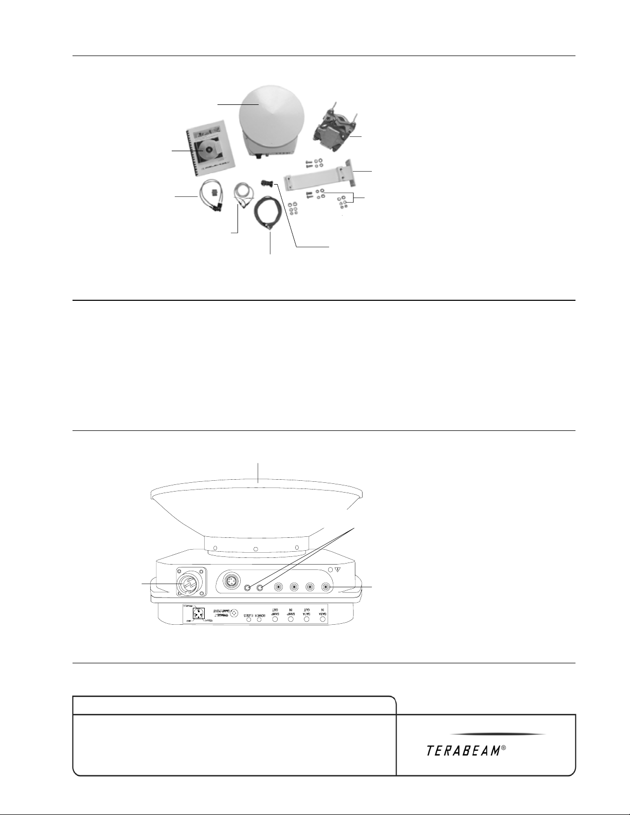
Figure 2-2: Gigalink Terminal Components
Transceiver
Software and
documentation
Adapter cable
and SC-SC coupler
Fiber loop-back
jumper cable
10 base-T
SNMP adapter cable
DC power
connector assembly
Spotting scope
Hardware
Mount arm
Pole-mounted
gimbal
2.1.1 Gigalink Transceiver
Gigalink transceivers are either high band or low band. To establish a link, it is necessary to have one
high-band and one low-band transceiver. The band (i.e., frequency) is printed on the transceiver’s
identification label (see Section 9.2.4, Labeling Requirements). All Gigalink electrical and network
connections are made at the base of the transceiver and are clearly labeled (see Figure 2-3). Two
light-emitting diodes (LEDs) indicate the status of the power and fuses. No network cables or power
cords are provided with the Gigalink.
Figure 2-3: Gigalink Transceiver Connector Interfaces
DC power
interface
LEDs
Fiber connections
Antenna
Note: The transceiver is shown with the
connector interface caps removed.
Chapter 2 System Overview 2-3
Proxim Wireless
Gigalink 6451e Field Installation and Service Manual
Document Number: 040-1234-0000 / Revision: F
Release Date: 10/14/04 / PrintDate: 09/27/06
Proprietary and Confidential
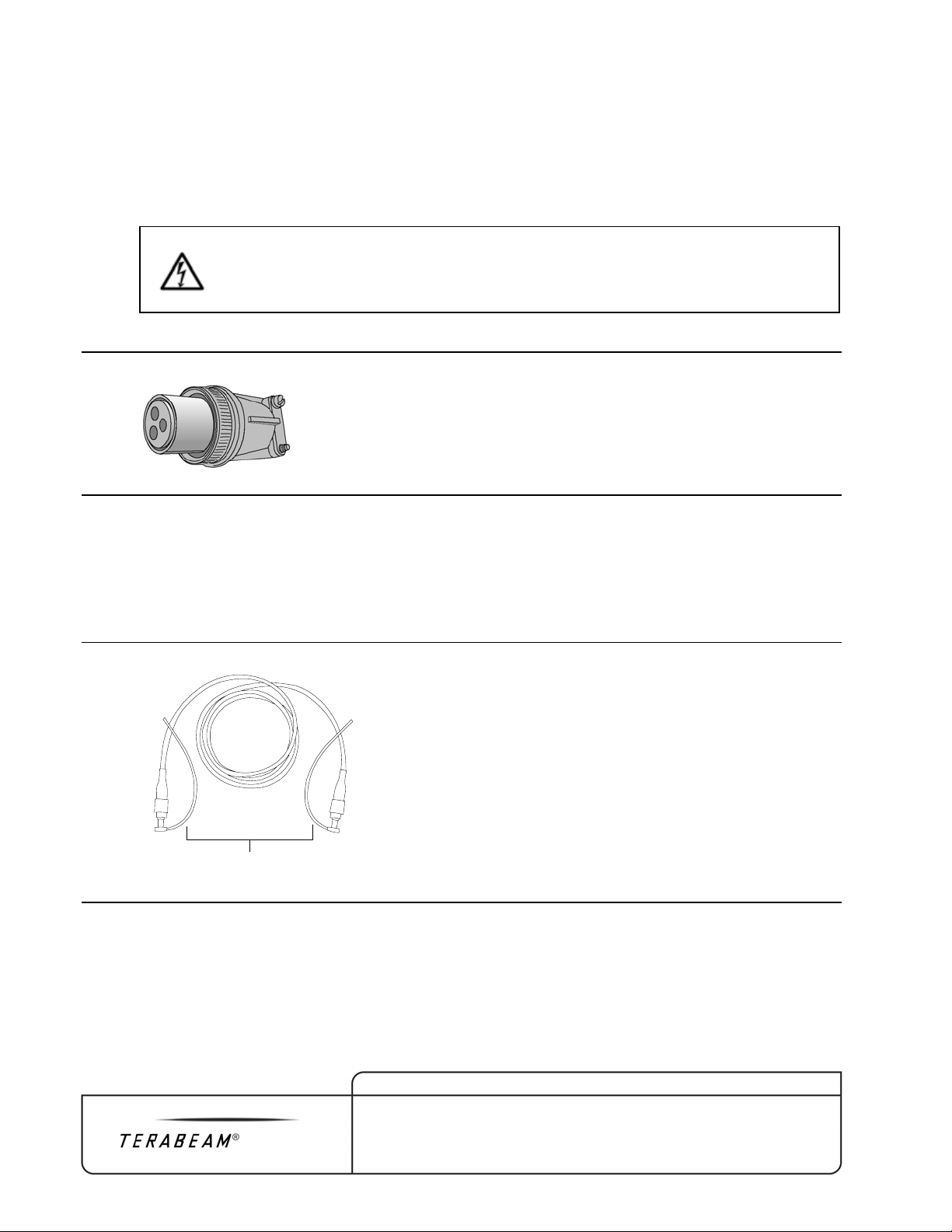
2.1.2 DC Power Connector Assembly
Each Gigalink is supplied with a military-style DC power connector assembly suitable for terminating
a standard three conductor, 12- to 16-AWG wire (see Figure 2-4). Wire specifications are provided in
Section 3.3, Electrical Service. Detailed DC power connector assembly instructions are provided in
Appendix A.
Warning – The DC power cable must be assembled by a qualified technician
according to the instructions provided in Appendix A and in compliance with all
applicable local electrical codes. Improper wiring of the DC power cable can cause
damage to the Gigalink transceiver and/or electric shock.
Figure 2-4: DC Power Connector Assembly
2.1.3 Fiber Loop-Back Jumper Cable
The fiber loop-back jumper cable is used during initial alignment or to facilitate troubleshooting (see
Figure 2-5). The two FC connectors on the cable attach to the FC data ports on the Gigalink
transceiver to loop back the data.
Figure 2-5: Fiber Loop-Back Jumper Cable
FC
connectors
2-4 Chapter 2 System Overview
Proxim Wireless Gigalink 6451e Field Installation and Service Manual
Document Number: 040-1234-0000 / Revision: F
Release Date: 10/14/04 / PrintDate: 09/27/06
Proprietary and Confidential
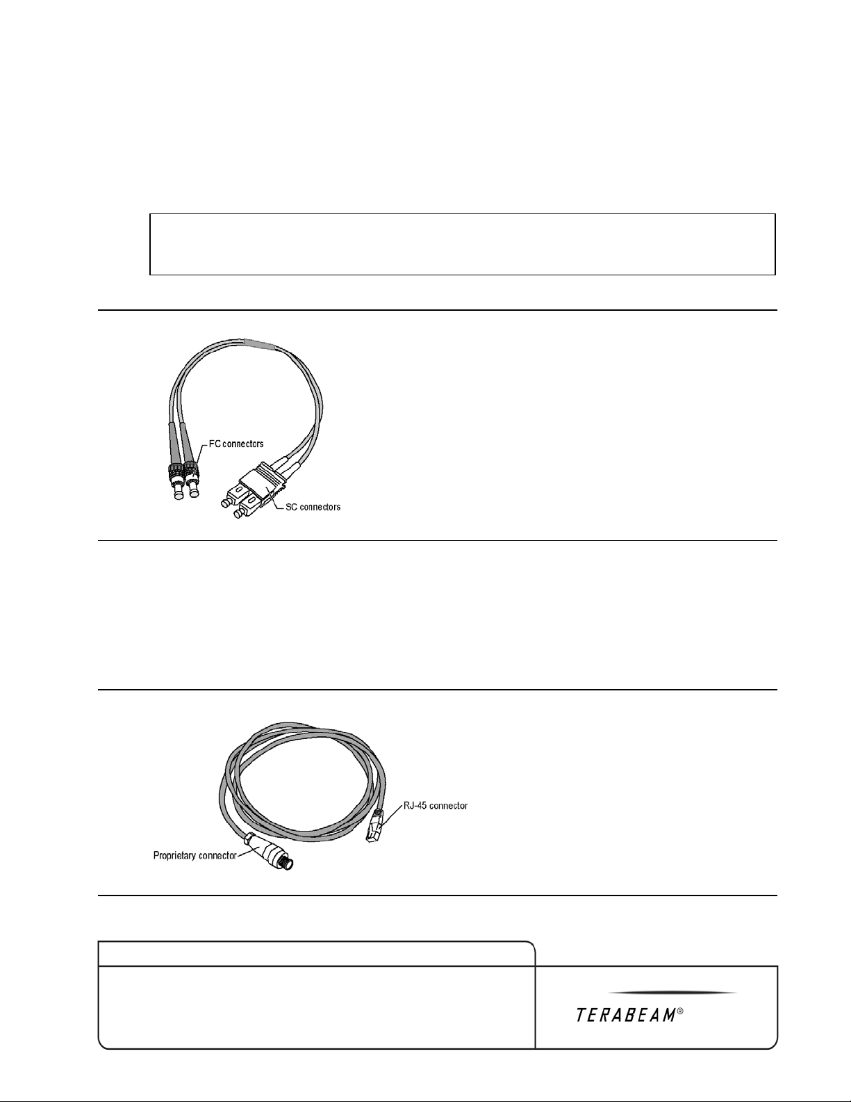
2.1.4 Adapter Cable
The adapter cable is used to temporarily connect the transceiver to test or other equipment during
initial alignment or to facilitate troubleshooting (see Figure 2-6). The two FC connectors on the cable
attach to the FC data ports on the Gigalink transceiver. The two SC connectors attach to standard
SC-terminated cables through use of provided SC-SC coupler.
Note: The adapter cable is not a weatherproof cable and should only be used for temporary
connections.
Figure 2-6: Adapter Cable
2.1.5 100Base-TX Adapter Cable
A 100Base-TX (SNMP) adapter cable is used to connect the transceiver to the field service laptop for
installation and onsite monitoring (see Figure 2-7). The 2.2-m (86-in.) cable is fitted with an RJ-45
connector at one end for connection to the laptop and has a proprietary connector at the other end for
connection to the transceiver.
Figure 2-7: 100Base-TX Adapter Cable
Chapter 2 System Overview 2-5
Proxim Wireless
Gigalink 6451e Field Installation and Service Manual
Document Number: 040-1234-0000 / Revision: F
Release Date: 10/14/04 / PrintDate: 09/27/06
Proprietary and Confidential
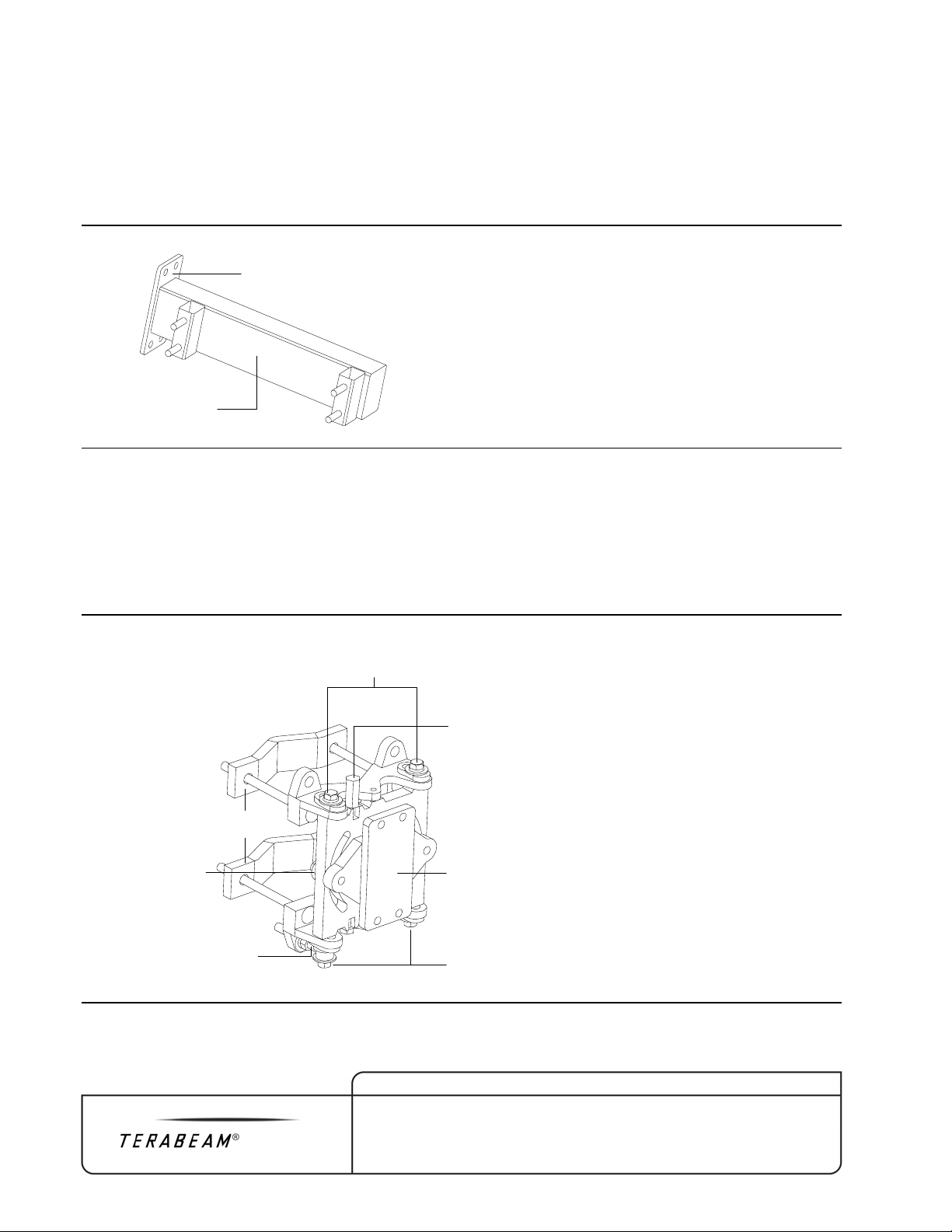
2.1.6 Mount Arm
The mount arm holds the transceiver is attached to the pole-mounted gimbal (see Figure 2-8).
Features of the mount arm include a mount arm interface plate and the transceiver interface, which
has four 3/8-16 studs that fit into holes located in the housing on both sides of the Gigalink
transceiver.
Figure 2-8: Mount Arm
Mount arm
interface plate
Transceiver
interface
2.1.7 Pole-Mounted Gimbal
The pole-mounted gimbal is a pre-assembled mount that allows the Gigalink transceiver to be
attached to a pole and then rotated for precise alignment (see Figure 2-9). Key features of the mount
include the pole clamps, the mount arm interface plate, the elevation axis bolts and adjustment screw,
and the azimuth hex bolts and azimuth axis eyebolt.
Figure 2-9: Pole-Mounted Gimbal
Elevation axis
adjustment screw
Mount arm
interface plate
Elevation
axis bolts (2)
Azimuth
axis eyebolt
Azimuth
hex bolts
Azimuth hex bolts
Pole
clamps
2-6 Chapter 2 System Overview
Proxim Wireless Gigalink 6451e Field Installation and Service Manual
Document Number: 040-1234-0000 / Revision: F
Release Date: 10/14/04 / PrintDate: 09/27/06
Proprietary and Confidential

Optional Universal AC Power Module
Refer to Appendix E, Universal AC Power Module.
Chapter 2 System Overview 2-7
Proxim Wireless
Gigalink 6451e Field Installation and Service Manual
Document Number: 040-1234-0000 / Revision: F
Release Date: 10/14/04 / PrintDate: 09/27/06
Proprietary and Confidential

Table of contents
Other TERABEAM Radio manuals


