3
Safety Measures
STANDARD RISK
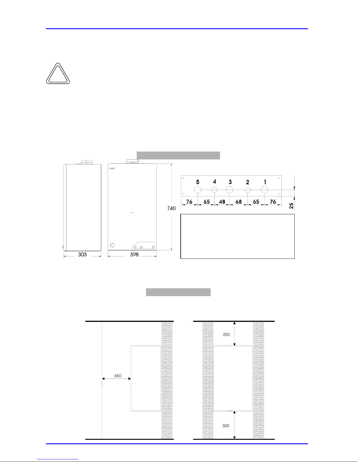
The appliance must be installed on a vibration-free
solid wall.Noise during operation.
Electric shock when coming into contact with live
wires.
Explosion, fire or intoxication due to gas leakage
from damaged tubes.
Be careful not to damage or perforate the wall or
the existing electrical cables and pipes.
Damage to existing systems
Flooding due to leakage of liquid from damaged
tubes.
Use appropriate cable section to carry out the
electrical connections.Fire risk due to overheating caused by electrical
current flowing through undersized cables.
Electric shock when coming into contact with live
wires.
Explosion, fire or intoxication due to gas leakage
from damaged tubes.
Protect pipes and connection cables so that they
cannot be damaged
Flooding due to leakage of liquid from damaged
tubes.
Electric shock when coming into contact with live
wires that are not properly installed.
Explosion, fire or intoxication due to incorrect
ventilation of discharge fume pipes.
Make sure that the area where the appliance is
installed and the systems to which it is connected
comply with the regulations in force
Damage to the appliance due to malfunction.
Risk of personal injury from ejected splinters or
fragments, dust inhalation, impacts, cuts,
punctures and scratches.
Use adequate tools correctly (make sure that the
tools are not damaged and that the handles are
complete and correctly fixed). Secure them.
Replace them after use.
Damage to the appliance or adjacent objects due
to ejected splinters, knocks and cuts.
Risk of personal injury from ejected splinters or
fragments, dust inhalation, impacts, cuts,
punctures, scratches, noise or vibration.
Use adequate electrical equipment correctly (make
sure that the feed cable and the plug are not
damaged and that the parts with rotary and
reciprocating motions are adequately fixed). Make
sure that the feed cables do not cause an
obstruction and are correctly secured. Disconnect
and replace them after use.
Damage to the appliance or adjacent objects due
to ejected splinters, knocks and cuts.
Make sure that the rolling ladder is sturdy and
firmly set against the wall, that the steps are not
damaged or slippery, and that the ladder is fitted
with a handrail up to the top and with a protected
platform.
Risk of personal injury due to accidental falls from
a height or from the severing of limbs (double-
sided ladder).
Make sure that the fall-safe ladder is sturdy and
firmly set against the wall, that the steps are not
damaged or slippery. Make sure that ladder does
not move when in use. Any operation requires the
assistance of a second person.
Risk of personal injury due to accidental falls from
a height.
Make sure that, when carrying out interventions at
a height (of at least two-metres) all safety
measures for preventing accidental falls-protection
guards surrounding the working area or personal
harnesses-have been taken. Make sure that there
are no dangerous objects in the path of a possible
fall and that the fall would be cushioned by a semi-
rigid or soft surface.
Risk of personal injury due to accidental falls from
a height.