Terra PA420T User manual

Programmable multiband ampliers PA420T, PA321TP
Vers. 1.01
1
EN
Manual in .pdf
Product description
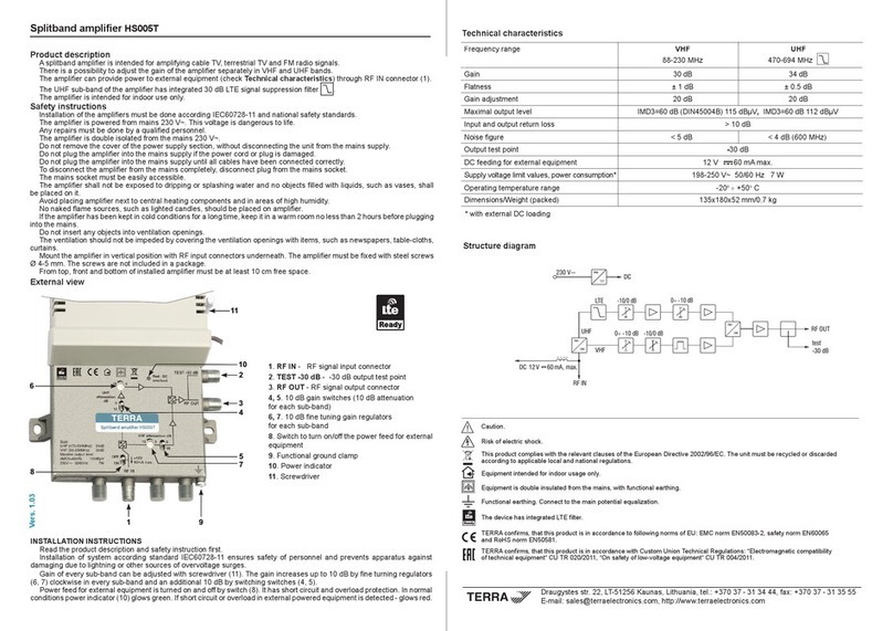
Programmable multiband ampliers with digital ltering are designed to amplify DTT signals in the VHF and UHF bands and
FM radio signals. These ampliers have up to 20 programmable high selectivity digital lters for DTT with a wide individual
AGC range and can be programmed to lter any VHF (170 ... 230 MHz), UHF (470 ... 694 MHz) channel.
The ampliers are also characterized by easy installation, a wide input level range, high selectivity, low power consumption,
high output level, output test point and LED indication (see Installation section). Each of the 20 lters allows to balance
adjacent channels due to high selectivity. Channels are automatically aligned according to the programmed UHF output
level and equalizer value. VHF channels will be adjusted according to the programmed UHF output level, the FM input has
a programmable gain control. DC power is provided through certain DTT inputs (switchable), see Specication.
The series consist of:
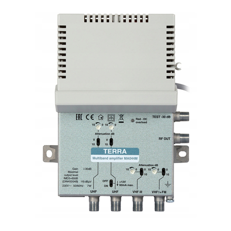
PA420T has 3 DTT inputs (2xVHF/UHF and 1xUHF) with 5G LTE ltering and 1 FM input. It has its own power supply.
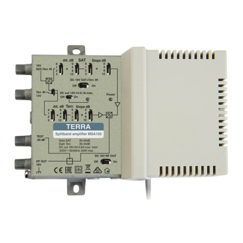
PA321T has 2 DTT inputs (VHF/UHF) with 5G LTE ltering and 1 FM input. It has two powering modes:
- via DC IN (DC jack) from external 12 V DC power supply;
- via RF output from suitable receiver or 12 V DC power supply using power inserter.
The housing of ampliers meets more stringent screening requirements according to EN50083-2, class A.
The ampliers are intended for indoor use only.
Safety instructions
Installation of the ampliers must be done according to IEC60728-11 and national safety standards.
The amplier PA420T is powered from mains 230 V~. This voltage is dangerous to life.
The amplier PA420T is double isolated from the mains 230 V~.
The amplier PA321TP is powered from the external stabilized power supply +12 V DC. This voltage is not dangerous to life.
Any repairs must be done by skilled personnel.
Do not remove the cover of the power supply section, without disconnecting the unit from the mains supply.
Do not plug the amplier into the mains supply if the power cord or plug is damaged.
Do not plug the amplier into the mains supply until all cables have been connected correctly.
The mains socket must be easily accessible.
The amplier shall not be exposed to dripping or splashing water.
Avoid placing amplier next to central heating components, near highly combustible materials and in areas of high humidity.
If the amplier has been kept in cold conditions for a long time, keep it in a warm room no less than 2 hours before plugging
it into the mains.
Do not insert any objects into ventilation openings.
The ventilation should not be impeded by covering the amplier with items, such as newspapers, table-cloths, curtains.
Mount the amplier on not ammable wall or in not ammable installation box in vertical position with power supply unit on
the right side. Mount in locations where children not likely to be present.
From top, front and bottom of installed amplier must be at least 10 cm free space.
MONTAGE VIEW
Mount the amplier on the vertical position with power supply unit on the right side. The amplier must be xed with steel
screws Ø 4-5 mm. The screws are not included in a package.
IMPORTANT WARNINGS!
Before connecting any products to a system, it is essential to make sure the system power supply is switched o. Avoid
short-circuit or overload of any power supply. Never “HOT-SWAP” any system components as this may result in damage to
the newly introduced or existing components.
Scan for downloading TERRnet App
from Google Play:

2
External view of amplier PA420T
1- IN 1 / DC out - VHF / UHF input 1, DC output. F type.
2- IN 2 / DC out - VHF / UHF input 2, DC output. F type.
3- IN 3 - UHF input. F type.
4-FM - FM input. F type.
5- RF OUT - RF signal output connector (combined DTT and FM inputs). F type.
6- TEST -30 dB - RF output signal test point. F type.
7- Control - programming port.
8- Adjust - adjust LED (green)
9- Error - error LED (red)
10 -power cord
11 -functional ground clamp
12 -mounting supports
Figure 1. External view of the amplier PA420T
1
3
2
5
4
6
7
8 9
10
11
12
position of
control port
7
12

External view of amplier PA321TP
1- IN 1 / DC out - VHF / UHF input 1, DC output. F type.
2- IN 2 - VHF / UHF input 2. F type.
3-FM - FM input. F type.
4- RF OUT / DC IN - RF signal output connector (combined DTT and FM inputs) / DC IN. F type.
5- TEST -30 dB - RF output signal test point. F type.
6- DC IN 12 V - DC entry 3.5/1.3 mm. DC jack.
7- Control - programming input.
8- Adjust - adjust LED (green)
9- Error - error LED (red)
10 -functional ground clamp
11 -mounting supports
Figure 2. External view of the amplier PA321TP
The power supply unit 12 V DC SYS1381N-1212-W2E:
3.5 mm/1.3 mm DC jack;
The power supply is supplied with the amplier.
3
Requirements for external power supply unit (PSU)
• Output voltage 12 V
• Output current recommended to use
PSU with 50% extra power reserve
• Ripple at single and/or < 10 mV p-p
double mains frequency
• Ripple & noise < 200 mV p-p
• Short circuit protection
• Double insulated (marked )
• Meet EN 55022 class B conducted emissions requirements,
measuring with grounded load
Installation and conguration instructions
Read the safety instruction rst.
Fit amplier on mounting place and connect all necessary RF cables, connect 75 Ω loads to the unused F sockets,
power on amplier. Adjust (green) and Error (red) LED’s blinking simultaneously briey. Adjust LED light up after that.
All congurations will be made with TERRnet App (see TERRnet App).
Connect Windows PC or Android smartphone to the amplier.
Select the necessary country (channels chart).
Select the necessary channels, output level, equalizer, FM gain and send it to the device.
Input channels numbers can’t be the same in dierent inputs.
Don’t select empty channels.
Reduce output level if use more than 6 MUX (see Technical characteristics).
Keep FM max output level 10 dB less than DTT signals.
During the parameters sending Adjust LED blinking (green). Error LED blinking (red) if the input level is too low or too
high for at least one selected channel.
7
1
2
3
4 5
6
8 9
10
11
11

4
Technical characteristics
Type PA420T
* programming from Android device via OTG cable, this cable is sold separately
** without external DC load, with maximal external DC load - 9 W
RF inputs
Frequency range FM 87-108 MHz
2xVHFIII/UHF1 174-240 MHz / 470-694 MHz
UHF 470-694 MHz
RF input level FM 69-89 dBµV
VHF/UHF 50-100 dBµV
Gain FM 29 dB
VHF/UHF 63 dB max.
Noise gure 7 dB
AGC VHF/UHF 46 dB in each lter
Slope adjustment FM -
VHFIII/DAB/UHF 5 dB
Selectivity VHF/UHF ±1 MHz > 30 dB
FM ±20 MHz > 20 dB
LTE 5G
Number of channels 20 max.
Number of lters 20 max.
RF output
Output level FM 106 dBµV max.
UHF 113 dBµV max. (1 - 6 MUX)
110 dBµV max. (7 - 12 MUX)
109 dBµV max. (13 - 16 MUX)
108 dBµV max. (17 - 20 MUX)
VHF 3 dB less than UHF
RF output adjustment FM 0 ÷ -20 dB
VHF/UHF common 0 ÷ -20 dB
VHF/UHF each channel ± 3 dB
RF test 30 dB
Powering
DC feeding VHFIII/UHF1
12 V 100 mA per input, OFF/ON
for external VHFIII/UHF2
Power consumption 230 V~ 50/60 Hz 6 W**
General
Return loss > 10 dB
Operating temperature -200 C ÷ +500 C
Dimensions/Weight (packed) 192x147x55 mm/0.66 kg
Recommended accessories:
1. Power supply SYS1381N-1212-W2E (12 V 1 A) (for PA321T).
2. Power inserter PI018 (for PA321T).
3. OTG cable.
Software update
Download the new software version to Windows PC. Connect the amplier to the PC (see TERRnet App). Remove the
plastic cap from the “F” connector nearest to the “Control” connector. Connect 75 Ω load to it. Power amplier. Copy the new
software le to the appeared disk in the le browser. Remove 75 Ω load and reconnect power.
pr.
pr.
pr.
pr.
pr.
software control
pr.

Type PA321TP
* power inserter is sold separately
** programming from Android device via OTG cable, this cable is sold separately
*** PA321TP is packed with external power supply SYS1381N-1212-W2E
**** without external DC load, with maximal external DC load - 0.55 A max.
RF inputs
Frequency range FM 87-108 MHz
2xVHFIII/UHF1 174-240 MHz / 470-694 MHz
RF input level FM 69-89 dBµV
VHF/UHF 50-100 dBµV
Gain FM 29 dB
VHF/UHF 63 dB max.
Noise gure 7 dB
AGC VHF/UHF 46 dB in each lter
Slope adjustment FM -
VHFIII/UHF 5 dB
Selectivity VHF/UHF ±1 MHz > 30 dB
FM ±20 MHz > 20 dB
LTE 5G
Number of UHF channels 20 max.
Number of lters 20 max.
RF output
Output level FM 106 dBµV max.
UHF 113 dBµV max. (1 - 6 MUX)
110 dBµV max. (7 - 12 MUX)
109 dBµV max. (13 - 16 MUX)
108 dBµV max. (17 - 20 MUX)
VHF 3 dB less than UHF
RF output adjustment FM 0 ÷ -20 dB
VHF/UHF common 0 ÷ -20 dB
VHF/UHF each channel ± 3 dB
RF test 30 dB
Powering***
DC feeding for external VHFIII/UHF1 12 V 100 mA per input, OFF/ON
Supply voltage via 3.5/1.3 mm DC jack 12 ± 1 V
via RF output 12 ± 1 V
Current consumption 12 V 450 mA****
General
Return loss > 10 dB
Operating temperature -200 C ÷ +500 C
Dimensions/Weight (packed) 100x147x55 mm/0.54 kg
Technical characteristics
This product complies with the relevant clauses of the European Directive 2002/96/EC. The unit must be recycled or discarded
according to applicable local and national regulations.
Equipment intended for indoor usage only.
Equipment is double insulated from the mains, with functional earthing.
Functional earthing. Connect to the main potential equalization.
This product is in accordance to following norms of EU: EMC norm EN50083-2, safety norm EN IEC62368-1, RoHS norm EN50581.
This product is in accordance with Custom Union Technical Regulations: “Electromagnetic compatibility of technical equipment“
CU TR 020/2011, “On safety of low-voltage equipment“ CU TR 004/2011.
This product is in accordance with safety standard AS/NZS 60065 and EMC standards of Australia.
Draugystes str. 22, LT-51256 Kaunas, Lithuania, tel.: +370 37
-
31 34 44, fax: +370 37
-
31 35 55
E-mail: [email protected], http://www.terraelectronics.com
software control
pr.
pr.
pr.
pr.
pr.
This manual suits for next models
1
Table of contents
Other Terra Amplifier manuals
Popular Amplifier manuals by other brands
Alpine
Alpine PDX-M6 Service manual

Behringer
Behringer Ultrabass BXL1800 user manual

Studiomaster Professional
Studiomaster Professional XPA 40 instruction manual
Studio Technologies
Studio Technologies 80 M80-00273 user guide
Busch-Jaeger
Busch-Jaeger 8211 U operating instructions

Redgum
Redgum RGM175ENR owner's manual
Beale Xpress
Beale Xpress IA-1250 user guide

Contacta
Contacta PLALS-V Setup guide
Carson
Carson SA-430 Installation and operating instructions

Melles Griot
Melles Griot 13 AMP 003 Operator's manual

Genz Benz
Genz Benz NEOX400-210T owner's manual
Soundstream
Soundstream RUBICON 204 Owner's manual and installation guide
