Terra UA410 User manual
Product description
The output amplier UA410 is intended to amplify and summarize signals in modular system as well as stand-alone unit.
The UA410 has wide range of output level selection, which includes interstage and input gain adjustments.
Two selectable input modes: input + input test point or two inputs.
Both output and switchable input test points are directional.
The output amplier is intended for indoor use only.
Safety instructions
Installation of the amplier must be done according IEC60728-11 and local safety standards.
The amplier is powered from power supply unit (PSU) +12 V. This voltage is not dangerous to life.
Output of PSU +12 V must have a short circuit protection.
Any repairs must be done by a qualied personnel.
Do not plug the PSU +12 V into the mains socket until all modules cables have been connected correctly;
The mains socket of PSU +12 V must be easily accessible;
To disconnect the amplier, disconnect the PSU +12 V from the mains.
The amplier shall not be exposed to dripping or splashing water and no objects lled with liquids, such as vases, shall
be placed on it;
Avoid placing amplier next to central heating components and in areas of high humidity;
No naked ame sources, such as lighted candles, should be placed on amplier;
If the amplier has been kept in cold conditions for a long time, keep it in a warm room no less than 2 hours before
plugging into the mains;
The ventilation should not be impeded by covering the ventilation openings with items, such as newspapers, table-cloths,
curtains;
Mount the amplier in vertical position;
From top, front and bottom of installed amplier must be at least 10 cm free space.
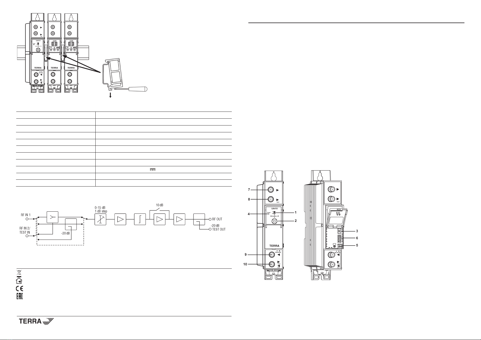
External view
1 - 10 dB attenuation switch
2 - 15 dB attenuation rotary switch with 1 dB step
3 - input mode switch (input and input test or 2 inputs)
4 - power on LED indicator
5 - +12 V powering input (screw terminal)
6 - powering and power distribution bus connector
7 - ► - RF output (F socket)
8 - ► - RF output test point (F socket)
9 - ◄ - RF input (F socket)
10 - ►/◄ - switchable: RF input test point / auxiliary input
(F socket)
Figure 1. External view of the amplier
Draugystes str. 22, LT-51256 Kaunas, Lithuania, tel.: +370 37
-
31 34 44, fax: +370 37
-
31 35 55
E-mail: [email protected], http://www.terraelectronics.com
Technical specications
Output amplier UA410
Frequency range 47-862 MHz
Gain, switchable 30/40 dB
Output level CTB (-60 dB, EN50083-3) 110 dBµV
Output level CSO (-60 dB, EN50083-3) 111 dBµV
Noise figure (2 inputs / input and test point) 11 / 8 dB
Gain adjustment 15 dB by 1 dB step
Test points -20 dB ±0.75 dB
Supply voltage 12 ±1 V
Current consumption 0.8 A
Operating temperature range 0o÷ + 50oC
Dimensions/Weight (packed) 198x107.5x48.5 mm/1.2 kg
Structure diagram
Figure 7. Structure diagram
Figure 6. Mounting or removing to/from
DIN rail of plastic spacers (supplied).
This product complies with the relevant clauses of the European Directive 2002/96/EC. The unit must be recycled
or discarded according to applicable local and national regulations.
Equipment intended for indoor usage only.
TERRA conrms, that this product is in accordance to following norms of EU: EMC norm EN50083-2,safety norm EN60065 and RoHS norm EN50581.
TERRA conrms, that this product is in accordance with Custom Union Technical Regulations: “Electromagnetic compatibility of technical
equipment“ CU TR 020/2011, “On safety of low-voltage equipment“ CU TR 004/2011.
Vers. 1.01

Installation instructions
1. Read the safety instructions rst.
2. Mount the amplier on the DIN rail or on the wall following the mounting instructions listed below.
3. Connections of the cables must be made according to the diagram in Figure 2. There are two ways for power supply
connection: 12 V DC voltage can be supplied through DC input terminal or units of the system can be joined together using
power distribution bus while only one of them connected to 12 V power supply unit.
4. Power supply can be connected only when all connections are nished.
Operating
Input mode can be selected using input mode switch (3). One or two inputs modes are available. The one input mode
offers input test feature, while the two inputs mode enables to summarize and amplify signals from both: RF input and auxilary
input. The amplier offers wide range of attenuation. Attenuation interstage switch (1) allows to provide output signal level
attenuated by 10 dB. Fine tunning of the output level can be achieved using attenuation rotary switch (2), which broadens
attenuation range up to 15 dB with 1 dB steps adjustment.
Installation examples:
Connection of cables
Mounting on DIN rail
Figure 4. Mounting to DIN rail
Figure 5. Mounting from DIN rail
Perpendicular to the wall Parallel to the wall
Figure 3. Mounting of amplier
Figure 2. Installation example 2
UA410
Mounting
Mounting on a wall by screws Mounting on a bracket (supplied)
Figure 1. Installation example 1
Other Terra Amplifier manuals


