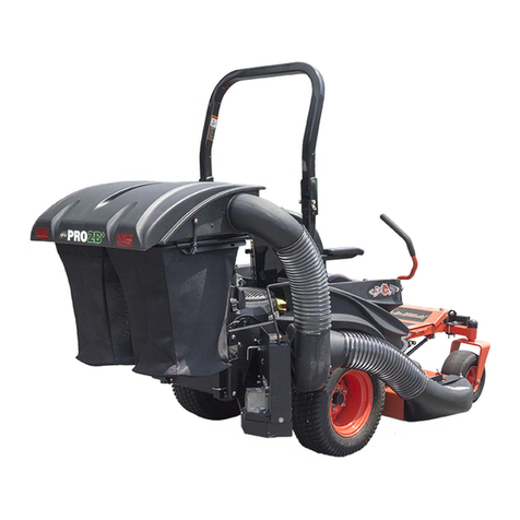
TerraKing TKV 20 User manual

OPERATOR’S MANUAL
TKV 20 Material Collection System
TK95044
8/8/2018
For your safety, please read and save all
safety and operating instructions prior to
using equipment.
GREY
PMS 427
CMYK C19 M15 Y16 K0
RGB R204 G204 B204
Hex #CCCCCC
Threa Light Ash
BLUE
PMS 647
CMYK C91 M60 Y4 K0
RGB R20 G103 B172
Hex #1268AC
Thread Farm Blue
ORANGE
PMS 715
CMYK C0 M69 Y98 K0
RGB R243 G113 B33
Hex #F37121
Thread Tennessee Orange
BLACK
PMS TBD
CMYK C0 M0 Y0 K100
RGB R0 G0 B0
Hex #000000
Thread Black
GREY
PMS 428
CMYK C27 M17 Y17 K0
RGB R195 G197 B200
Hex #c3c5c8
Thread Light Gray
BLUE
PMS 287
CMYK C100 M87 Y20 K10
RGB R32 G61 B124
Hex #203d7c
Thread Dark Royal
GOLD
PMS 3965
CMYK C1 M14 Y99 K0
RGB R254 G212 B2
Hex #231f20
Thread NFL Yellow

2
Introduction
Table of Contents
Introduction .................................................................... 2
Product Compatibility .................................................... 2
Safety Labels ..............................................................3-5
Safety ............................................................................. 6
Parts in Kit ..................................................................... 7
Tractor and Other Requirements ................................... 7
Assembly .................................................................. 8 -11
Operation ..................................................................... 12
Troubleshooting ...................................................... 13-14
Maintenance ........................................................... 15 -17
Specifications............................................................... 18
Warranty....................................................................... 20
Using Your Operator’s Manual
Read this entire manual in its entirety, especially the safety
information, before operating.
This manual is an important part of your TKV 20 Material
Collection System (MCS). Keep this manual in a
convenient location so that it can be accessed easily.
Use the safety and operating information in this manual
in order to operate and service the attachment safely and
correctly.
If you have any questions or concerns with the assembly,
installation, or operation of the TKV 20, contact TerraKing
Warranty information regarding the TKV 20 can be found in
the Warranty section of this manual.
Product Compatibility
The TKV 20 is designed for use on sub-compact and
compact tractors with mid-mount side discharge mower
decks. Refer to the Tractor Requirements section
on page 7 and to your tractor’s operators manual to
determine compatibility.

3
Safety Labels
Understanding the Machine Safety Labels
Safety labels shown in this section are placed in
important areas on your machine to draw attention to
potential safety hazards.
On your machine safety labels, the words DANGER,
WARNING, and CAUTION are used with this safety-alert
symbol. DANGER identies the most serious hazards.
This manual explains potential safety hazards whenever
necessary in special messages that are identied with the
word, CAUTION, and the safety-alert symbol.
Be sure to replace missing or damaged safety labels.
Use this manual for correct safety label placement.
Additional safety information on parts and components
sourced from suppliers might not be represented in this
section.
ST48295
AVOID INJURY FROM
MOVING PARTS
• Keep hands, fingers
and feet away
• Disconnect power
before servicing
ST48453
AVOID INJURY FROM
MOVING PARTS
• Do not operate without
shields in place
• Disconnect PTO
before servicing
ST48454
AVOID INJURY FROM
MOVING PARTS
• Do not operate without
hose connected
• Disconnect PTO
before servicing
DANGER
ROTATING DRIVELINE:
CONTACT CAN CAUSE DEATH
KEEP AWAY!
DO NOT OPERATE WITHOUT:
• All driveline gua rds, tractor and equipment
shields in place
• Dr ivelines securely attached at both ends
• Dr iveline guards that turn fre ely on driveli ne

4
Safety Labels
ST48454
AVOID INJURY FROM
MOVING PARTS
• Do not operate without
hose connected
• Disconnect PTO
before servicing
WARNING
To Avoid Injury From Thrown Objects
• Keep bystanders away
• Shut off engine before opening hopper top
• Keep chutes in place
• Never allow riders on hopper top or on frame
• Disconnect power before servicing
DANGER
Bagger May Impair Rear Vision
• Look down and behind before and while backing
WARNING
To Avoid Injury From Moving Parts
• Do not operate without hose connected
• Disconnect PTO shaft before servicing
CAUTION
To Avoid Injury
• Install front ballast per tractor’s operator’s manual
ST48295
AVOID INJURY FROM
MOVING PARTS
• Keep hands, fingers
and feet away
• Disconnect power
before servicing
WARNING
Avoid Injury From Moving Parts
• Keep hands, feet and clothing away
• Disconnect mechanical and electrical power
before servicing

5
CAUTION
No Step
• Do not step, stand or sit on this surface
• Improper use may cause injury and/or equipment damage
Safety Labels
DANGER
ROTATING DRIVELINE:
CONTACT CAN CAUSE DEATH
KEEP AWAY!
DO NOT OPERATE WITHOUT:
• All driveline guards, tractor and equipment
shields in place
• Drivelines securely attached at both ends
• Driveline guards that turn freely on driveline
DANGER
Rotating Driveline: Contact Can Cause Death
Keep Away!
Do Not Operate Without:
• All driveline guards, tractor and equipment
shields in place
• Drivelines securely attached at both ends
• Driveline guards that turn freely on driveline
ST48453
AVOID INJURY FROM
MOVING PARTS
• Do not operate without
shields in place
• Disconnect PTO
before servicing
WARNING
To Avoid Injury From Moving Parts
• Do not operate without shields in place
• Disconnect PTO shaft before servicing

6
Safety
General Safety
• The TKV 20 is limited to collecting only grass or leaves.
• Be aware when maneuvering your machine because
the TKV 20 increases vehicle length and also alters its
center of gravity.
• Be aware of the potential pinch point when closing
the tailgate and lid.
• DO NOT allow anyone to ride in or on the TKV 20.
Operating Safely
• Read the tractor and this operator’s manual carefully.
Be thoroughly familiar with the controls and the
proper use of the equipment. Know how to stop the
tractor and disengage the controls quickly.
• The TKV 20 is only intended for use in lawn and property
maintenance applications. TerraKing does not advise
or recommend this product for any other uses.
• Do not modify the TKV 20’s safety devices. Unauthorized
modifications may impair its function, safety, and
void the warranty.
• Do not let children or an untrained person
operate machine.
• Make any necessary adjustments before you
operate. Never attempt to make any adjustments
while the engine is running, unless if recommended
in adjustment procedure.
• Look behind machine before and while you back up.
Back up carefully.
• Do not let anyone, especially children, ride on
machine or attachment. Riders are subject to injury
such as being struck by foreign objects and being
thrown off. Riders may also obstruct the operator’s
view and alter weight distribution, resulting in the
machine being operated in an unsafe manner.
• Disengage any power to the attachment when the
machine is transported or not in use.
Parking Safety
1. Stop machine on a level surface
2. Lock the park brake
3. Stop the engine
4. Remove the key
5. Wait for engine and all moving parts to stop before
leaving the operator’s seat
Practice Safe Maintenance
• Only qualified, trained adults should service this machine.
• Understand service procedure before doing work.
Keep area clean and dry.
• Do not operate the engine in a confined space where
dangerous carbon monoxide fumes can collect.
• Never lubricate, service or adjust the machine or
attachment while it is moving. Keep safety devices in
place and in working condition. Keep hardware tight
and check regularly.
• Keep hands, feet, clothing, jewelry, and long hair away from
any moving parts, to prevent them from getting caught.
• Lower the TKV 20 completely to the ground or to an
existing attachment mechanical stop before servicing.
Disengage all power and stop the engine. Lock park
brake and remove the key. Let machine cool.
• Before servicing machine or attachment, carefully
release pressure from any components with stored
energy, such as hydraulic components and springs.
• Release hydraulic pressure by lowering attachment
or cutting units to the ground or to a mechanical stop
and move hydraulic control levers.
• Securely support any machine or attachment elements that
must be raised for service work. Use jack stands or lock
service latches to support components when needed.
• Keep all parts in good condition and properly installed.
Fix damage immediately. Replace worn or broken parts.
Replace all worn or damaged safety and instruction decals.
• Check all hardware at frequent intervals to be sure the
equipment is in safe working condition.
Wear Appropriate Safety Equipment
• Always wear eye protection when operating the machine.
• Wear close fitting clothing and safety equipment
appropriate for the job.
• While operating this machine, always wear substantial
footwear and long trousers. Do not operate the
equipment when barefoot or wearing open sandals.
• Wear a protective hearing device such as earplugs.
Loud noise can cause impairment or loss of hearing.
PLEASE READ: CRITICAL SAFETY WARNINGS
• DO NOT operate with the Steel Coil Hose off or
with the Cleanout Door open.
• DO NOT remove the Steel Coil Hose or open the
Cleanout Door while the tractor is running.
• DO NOT get near the rear of the tractor when the
PTO is engaged.
• DO NOT operate without front ballast.

7
Parts in Kit
A B
C D
Main Components
Description Qty.
ATKV 20 Main Assembly 1
B5' of 8"dia. Steel Coil Hose 1
CHose Clamps 2
DPTO Shaft 1
ESMV Sign 1
FPlastic End Cap 4
Other Requirements
Front Ballast
A full TKV 20 can weigh upwards of 600 pounds. Refer
to the manufacturer or dealership for proper ballasting
requirements.
Boot Kit (See Dealer)
A boot for your mower deck is required to attach the
TKV 20’s 8" dia. hose. Please consult your dealer to
acquire this part for your tractor.
Front Weight Bracket Kit
Part # TK95054 - Fits Kubota BX2360, BX2660, BX2370,
BX2670, BX2380, BX2680
Properly ballasting your tractor is important to ensure safe
operation with the TKV 20, especially when full.
A minimum of 200 lbs. (91 kg) is required.
Stay Chain Kit
Part # TK95052 - Fits Kubota BX2380, BX2680
Part # TK95053 - Fits Kubota BX2350, BX2360, BX2660,
BX2370, BX2670
This kit stabilizes a TKV 20 when in operation on inclines
and keeps the PTO shaft aligned when the tractor’s mower
deck is lowered
Wiring Harness Kit
Part # TK95051 - Fits Kubota BX2360, BX2660, BX2370,
BX2670, BX2380, BX2680
A dedicated wiring harness connects the TKV 20 to your
tractor. Included is a rocker switch with a ROPS-mounted
bracket to operate the electric actuator.
Tractor Requirements
Tractor horsepower should be within the range noted below.
Tractors outside the horsepower range must not be used.
Horsepower Rating............................................20-60 HP
Rear PTO Shaft......................................... 1-3/8" 6-Spline
Rear PTO Speed.................................................540 RPM
Hitch Type ...............Category 1 3-Point, Quick-Hitch Ready
3-Point Lift Capacity (24 in. behind link arms)....... 650 lb.
EF

8
Assembly
Initial Set Up
Attach TKV 20 to the tractor’s 3-point arms or Category 1
quick hitch.
Sizing the PTO Shaft
1. Slide PTO Shaft apart and connect the half with the
round hole to the TKV 20 and the spline half to the
tractor’s PTO shaft.
2. Lift and lower the 3-point arms to nd the position
where the two ends are closest together. Lay the two
sides of the shaft side by side and mark the amount
to be cut. Measurer this distance and cut the same
amount off both ends of the shields and both ends of
the shaft. Ensure that when the shaft is in the position
where the two shafts are farthest apart, there will still
be 1/2 of the shaft overlapping.
3. Cut the distance measured off each half of the shaft.
The guard should be cut back an additional 1.5-1.6
inches on each half to leave the end of the driveline
tube exposed.
4. Round off sharp edges and remove any burrs on
the driveline tubes. Apply good quality lithium
soap compatible E.P. grease (meeting the N.L.G.I.
#2 specication and containing no more than 1%
molybdenum disulde) to the outside of the smaller
diameter driveline tube.
5. Reassemble driveline halves together making sure they
slide (telescope) easily and ensure guards rotate freely.
WARNING: If the PTO shaft is cut too short, it can
disengage during operation and cause injury.
If you are unsure how to properly cut the PTO
shaft, please see your dealership.

9
Assembly
Connecting the PTO Shaft
1. Flip up the shield (A). With square key (B) in keyway
of the shaft, slide the PTO shaft onto the TKV 20 and
tighten the setscrew (C) to 28 +/-2 ft. lbs.
2. Connect the PTO shaft to the tractor’s PTO and
ensure lock pin (D) is engaged.
3. Lift the tractor’s 3-point arms up and down to ensure
that the PTO telescopes freely. Ensure that the PTO
shaft does not come apart when the 3-point arms are
at their highest point.
Blower Inlet Hose
1. Position mower deck in lowest mowing position.
2. Slide hose on front of blower as far as possible. Lay
other end beside the boot. Lift and lower the 3-point
arms to observe the distance between the boot and
the blower inlet. Cut the hose long enough to t in all
positions. The plastic can be cut with a utility knife,
but the wire requires wire cutters or a saw.
3. Slide clamp over hose and hose onto blower inlet.
Close the latch (A) to clamp. If clamp is too loose,
tighten the screw (B). To prevent stripping the screw,
unlatch before tightening.
4. Repeat step #3 on boot end.
5. Lift the tractor's 3-point arms up and down to ensure
that the blower hose moves freely.
6. Ensure that the blower hose does not contact
the ground during operation as this could cause
excessive wear or damage.
B
A
D
C B A

10
1. Install the two plastic end caps onto each foot of the
storage legs.
2. Lift TKV 20 with 3-point, remove the wire lock pin (A)
and the storage stand will drop off. With the shorter end
of the leg down slide the stand into the storage channel
(B), and fasten with the wire lock pin (C). Repeat this
step for the storage stand on the other side.
3. Set the stop down on the 3-point lever where the
PTO shaft sits horizontally. Adjust sway chains
and adjustable lift link on 3-point arms to level
attachment.
4. For hydraulic systems without position control, it is
recommended that the 3-point arms are chained to
ensure that the TKV 20’s PTO shaft remains horizontal.
Machine Set Up
Assembly
Repositioning the TKV 20’s 3-Point Hitch Pins
For wider tractors, the hose from the boot to the blower
may get close or touch the rear tire of the tractor. The
positioning of the TKV 20’s 3-point hitch pins can be
shifted to the right by 2-1/2" by following the steps below.
1. Remove the three shields (A).
2. Remove the side pin brackets (B and C), ip them
over and reinstall them in the opposite positions. B
is now reinstalled where C was, and vice versa. (This
allows the side pin to stay on the bracket). Reinstall
hardware and torque to 30 +/-1 ft. lbs.
WARNING: Place storage stands in storage
channel before mowing to prevent damage.
CAUTION: Operating PTO on an angle will cause
excessive wear or damage.
B C
A
C B
A

11
3. Remove the four bolts on the top pin brackets (D) and
support bracket (E) and slide them over to the next set
of holes on the frame. Reinstall hardware and torque to
30 +/-1 ft. lbs.
4. Reinstall the shields.
Assembly
D E

12
Operation
Before Operation
1. Make sure the lid is latched, the access door is
closed tightly and the hose is rmly connected and lid
extension is free to rotate outward.
2. Ensure that the tractor’s PTO Selection Lever on the
side console is in the position to allow the mid PTO
(mower deck) and the rear PTO (TKV 20) to operate.
3. Slowly lower the 3-point arms to a position where the
PTO shaft is horizontal for mowing.
4. For longer belt life on the mower deck and the TKV 20,
engage the PTO with the tractor at idle and throttle up
to full PTO RPMs. Lower the RPMs back to idle before
disengaging the PTO.
How to Determine If the Hopper is Full
NOTE: The rate at which the hopper lls is dependent upon
many factors including the type of material being collected
as well as its depth, moisture content and the tractor's speed.
NOTE: It is normal to have ne, dry grass escape from the
side panels during operation.
1. The lid fabric cover will begin to deate.
2. There will be a slight change upward in the pitch of
the blower.
Emptying the Hopper
1. To empty, disengage the PTO, lift the 3-point arms
all the way up and hold the rocker switch in the open
position until the tailgate is fully opened. Drive forward
away from the pile before closing. To close, hold the
rocker switch in the close position until fully closed.
NOTE: It is normal to hear the electric actuator make a
ratcheting sound when the PTO shaft is fully extended or
retracted while operating the rocker switch.
2. To prevent damage to the TKV 20, do not back up the
tractor while emptying material. Do not use the TKV
20’s tailgate to push material as damage may occur.
3. Lower the 3-point arms to position the PTO shaft
horizontally, engage PTO, and resume mowing.
WARNING: The TKV 20 will become unbalanced
when material is inside the hopper. Do not
disconnect the TKV 20 from the 3-point arms
or rest it on the storage stands while there is
material in the hopper.
Removal and Storage
1. Empty the hopper.
2. Lift the 3-point arms to their highest position.
3. Ensure that the storage stands are
installed at the lowest position and
that the tractor position labels (shown
at right) on both storage stands are
pointing towards the tractor.
4. If chains or a Stay Chain Kit were used
to prevent the TKV 20 from lowering
below the PTO horizontal position,
unhook the chains from
the tractor.
5. Disconnect and remove the wire to
the actuator switch.
6. Unlatch the hose clamps and remove the hose.
7. Lower the TKV 20 onto the storage stands.
8. Disconnect the tractor’s 3-point arms or quick hitch
from the TKV 20. This may require loosening the
tractor’s sway chains/links on the 3-point arms.
9. Disconnect the PTO shaft from the tractor.
Transportation
1. Ensure that the SMV sign on the back of the TKV 20
is in front of the hopper lid extension and visible from
the rear.
2. Transport the TKV20 as low as possible.
3. Ensure that the hopper lid extension is secured in
its lowered position if transporting on a trailer at
highway speeds.
T
R
A
C
T
O
R
IMPORTANT: Do not leave material inside the
hopper between uses and during storage.
Moisture can damage the hopper and damp
material is a re hazard.

13
WARNING: Rotating blades are dangerous.
Troubleshooting
Below are common symptoms that may be experienced
when the TKV 20 is in operation. Suggested solutions
are listed to help remedy the situation.
Blower Inlet Hose or Boot is Clogging Frequently
• Ensure the rear PTO is engaged and set at 540 RPM.
• Verify that the inlet hose and boot are not clogged.
If they are, consult the Unclogging Fan and Chute
section on page 14.
• Check the belt’s tension and inspect the belt for
wear. If the belt is loose, apply tension according
to Belt Tension section on page 15. If the belt
needs to be replaced, please see Belt Replacement
Instructions on page 15.
• If problem persists, operate the tractor at a slower
speed. If the grass you are collecting is too tall,
consider raising the deck height. If the material you
are collecting is too damp or wet, consider waiting
until it dries further.
Material is Blowing Out of the Vent on the Back
of the Chute or Side of the Hopper Lid
• Ensure that the hopper is not being overlled. If full,
empty the hopper.
• Verify that the holes in the screen of the hopper lid
are not lled with material. If plugged, clean screen
by wiping material from screen.
• Verify that hopper tailgate and its side panels do not
have lodged grass which can prevent the tailgate
from closing tightly.
• Verify the lid extension is free to rotate.
Belt are Slipping/Smoking During Startup
• Check to see if the fan is jammed. If so, consult
Unclogging Fan and Chute section on page 14.
• Check the belt tension and inspect for belt wear.
If the belt is loose, apply tension according to Belt
Tension section on page 15. If the belt needs to be
replaced, please see Belt Replacement Instructions
on page 15.
Fan or Drive System is Vibrating Excessively
• Check for loose hardware.
• Inspect fan blade for material buildup. If debris is
present, clean off the fan blades, supports, and plate.
• Check the tightness of the bolt on the center of the
fan shaft. If loose, apply red thread lock and re-tighten
to 18 +/- ft. lbs.
• Check the belt tension and inspect for belt wear.
If the belt is loose, apply tension according to Belt
Tension section on page 15. If the belt needs to be
replaced, please see Belt Replacement Instructions
on page 15.
• If vibration continues, contact TerraKing for support.
Bin Not Opening to Dump Collected Material
• Check the inline fuse located on the positive wire
near the battery. If the fuse is blown, replace it with a
30 amp slow-blow fuse.
• Make sure all wire connections are tight and clean.
• Make sure the wiring harness is not damaged and is
free of nicks.
• Using a voltmeter, verify that 12 volts DC is present
at the actuator connector when the rocker switch is
pressed in either direction. The voltage will be either
positive or negative depending on the switch position.
• If bin still does not open, contact TerraKing for support.

14
Unclogging Fan and Chute
The common symptoms of a clog include:
• Loss of tractor power
• Slipping belts
• Throwing material out from under deck
• Heavy and/or wet material
1. Ensure that the PTO and the mower deck have
stopped moving and turn off the tractor. Remove the
tractor’s key, set the parking brake and disconnect
the PTO shaft.
2. Loosen the lock knob (A).
3. Rotate the door (B) counterclockwise.
4. Reach into the chute and remove any clogged material.
The top of the chute may be reached from inside the
hopper.
5. Unlatch the hose clamp (C) and remove the hose.
6. Remove the clogged material from inside of the blower
housing.
7. Rotate the fan to ensure it is not stuck. Fan should
rotate with minimal resistance clockwise or counter-
clockwise. If fan is stuck, contact TerraKing for support.
CAUTION: Do not overfill hopper. Overfilling can
result in grass clogging chute. Material stuck in
chute may also fall into blower causing fan to
jam or vibrate on restart.
Troubleshooting
B
C
A
DANGER: Contact with rotating driveline (PTO)
can cause death or serious injury. Do not
attempt to service while tractor is running.
DANGER
ROTATING DRIVELINE:
CONTACT CAN CAUSE DEATH
KEEP AWAY!
DO NOT OPERATE WITHOUT:
• All driveline guards, tractor and equipment
shields in place
• Drivelines securely attached at both ends
• Driveline guards that turn freely on driveline

15
Belt Tension
1. Remove the front shields. Tension the belts (A)
by tightening the nuts (B) until the springs (C) are
stretched to 4.6" (inside hooks). Belt tension can be
veried using a spring gauge. Deection at center of
belt should be 4 lbs. at 1/4" deection.
2. Check the belt tension after 5 hours of initial use.
Check the belt for wear and re-tension if necessary
every 50 hours of use or annually (if less than 50 hours
per year).
Maintenance
Belt Replacement
Blower Belt
1. Disconnect PTO shaft.
2. Remove the two shields from locations (A) and loosen
the idler bolt (B).
3. Loosen nuts (C) and rotate the shield (D) as shown.
Remove the belt (E) from the pulley behind the blower.
4. Remove the belt from the large pulley and install a
new belt. (B51 V-belt)
5. Re-tighten the idler to proper belt tension and reinstall
the shields.
Maintenance Schedule
Each
Use
Initial
5 Hrs
8
Hrs
50
Hrs Annually
Belt tension: Check
and adjust/replace X X X
PTO shaft cross
and bearing, lube X X
PTO shaft
telescoping
member, lube
X X
Hopper screen,
cleanout X X
Fan and chute,
cleanout X
Drive frame
housing, cleanout X
B
C
A
A
B
C
D
E

16
Maintenance
Belt Replacement
PTO Belt
1. Disconnect the PTO shaft.
2. Remove the two shields (A) and the nut (B) from the
idler.
3. Remove the four bolts (C) to remove the center drive
pulley assembly.
4. Remove the four bolts (D) and the bolt on the idler
brackets (E).
5. Remove idler.
6. Twist the bracket (F) and remove the belt from the
pulley around the bracket. It may be necessary to
loosen the nuts (G) to allow the bearing to rotate in
the anges.
7. Install a new belt (B51 V-belt) onto the pulley and
reassemble the center drive-pulley assembly. Torque
the 3/8" bolts to 30 +/- ft. lbs.
8. Reinstall center drive-pulley assemly into drive frame
and torque bolts to 30 +/- ft. lbs.
9. Wrap the belt around the small pulley and reassemble
the idler to the proper belt tension.
10. Reinstall the two shields.
C
C
A
B
D
E
F
G

17
Maintenance
CAUTION: Replacement parts are not lubricated.
Replacement parts must be lubricated at
time of assembly and during use, per the lube
manufacturer’s recommendations.
PTO Shaft Lubrication
NOTE: See page 15 for recommended service intervals in
Maintenance Schedule table.
1. Lubricate all ttings with lithium soap compatible E.P.
grease meeting the N.L.G.I. #2 specications and
containing no more than 1% molybdenum disulde.
2. An E.P. grease meeting N.L.G.I. #2 specications
and containing 3% molybdenum disulde may be
substituted in the telescoping members only.
3. The rotating guard bushings should be lubricated
upon replacement.
Cleaning and Seasonal Storage
1. Empty the hopper before removing from the tractor.
2. Raise the hopper lid and clean the screen using a
cloth or soft-bristle brush.
3. Carefully remove any debris stuck to the fan and spray
with a light oil to prevent rusting.
4. Remove shields and clean out debris stuck in drive
frame. Reinstall the shields before storing.

18
Hopper
Capacity 20 bu. (705 L)
25 cu ft (0.7 m3)
Weight Empty: 390 lb. (177 kg)
Full: 650 lb. (295 Kg); Varies based on material
Ground Clearance 6-3/8 in. (162 mm.) (Distance between lower 3-point pins to bottom of hopper)
Material Sides: 1/16 in. (1.58 mm) aluminum
Gate: 1/16 in. (1.58 mm) steel
Storage Stands 1-1/2 in. (38.1 mm) square 11 gauge tubular steel
Blower System
Drive Type Belt
Belts Blower Belt: B51 V-belt
PTO Belt: B51 V-belt
Materials Fan: 7 gauge steel
Fan Housing Front and Rear: 11 gauge steel
Fan Housing Ring: 11 gauge 304 stainless steel
Fan Diameter 15-in. (381 mm.)
Number of Fan Blades 5
Fan Speed 3,000 RPM
Hose
Material Steel-coil vacuum hose
Diameter 8 in. (203 mm)
Length 5 ft (1.5 m)
Tractor Requirements
Horsepower Engine: 20+ HP
PTO: 17+ HP
Power Take-Off 540 RPM rear PTO shaft
3-Point Hitch Category 1 with 650+ lb. lift capacity
Electrical 12V / 30A connection
Mower Deck Mid-mount side-discharge deck
54 in. (1372 mm ) and 60 in. (1524 mm)
Counterweight Refer to the manufacturer or your dealer for proper ballasting requirements
Specifications

This page intentionally blank
19

20
Warranty
Limited Warranty
TerraKing’s products are guaranteed to be free from
defects in material and/or workmanship and to perform as
advertised when properly assembled, installed, used, and
maintained in accordance with written instructions. Failure
to adhere to this will void the warranty. TerraKing will not
be responsible for labor, loss, or consequential damage of
any kind or character caused by defective parts, or for charges
incurred in the replacement or repair of defective parts.
Warranty Period
The TerraKing TKV 20 Material Collection System is
warranted for a period of 1 (one) year after the purchase
date for residential use, and 6 (six) months after the
purchase date for commercial use. This product is
warranted by TerraKing to the original purchaser/
customer against defects in material and workmanship
under normal operating conditions.
All information, illustrations and specifications in this
manual are based on the latest information available at
the time of publication. TerraKing reserves the right to
make changes at any time without notice.
For service parts and customer support, contact
TerraKing by Superior Tech, Inc.
Form # TKOM-002B-08/18
Table of contents
