TerraWave TWSD16128PHC User manual
10521 Gulfdale, San Antonio, TX 78216 I www.terrawave.com I Email: sales@terrawave.com I Phone: 210-375-8482
Version 1.1 - Page 1
Installation Instructions
TWSD16128PHC

10521 Gulfdale, San Antonio, TX 78216 I www.terrawave.com I Email: sales@terrawave.com I Phone: 210-375-8482
Version 1.1 - Page 2
Introduction
The TWSD16128PHC is intended to be used with WLAN / Networking devices. The
TWSD16128PHC is intended to be used both indoors and outdoors and to provide NEMA 3R
protection with cooling and heating.
Maximum internal ambient is 45 Degrees Celsius.
Before installing this product, read these instructions carefully. Failure to follow these
instructions could lead to damaging the product or cause a hazardous condition.
Check the ratings on the products you intend to place inside the enclosure solution to ensure
that this is suitable for your application.
Precautions
Read and understand all instructions before you begin installing the unit
When installing and using this product, basic safety precautions should always be followed to
reduce the risk of electric shock, fire and injury to persons including the following:
All wiring that connects to this equipment must meet applicable local and national building
codes and network wiring standards for communications cable.
WARNING: To prevent the risk of electric shock and equipment damage, disconnect any
and all supply mains connection to the enclosure before installing, maintaining or trouble
shooting this product or any products inside the enclosure.
Retain the instructions for future reference.
Follow all warnings and instructions marked on the product.
Insulation on all cables and wires installed the service center must either be PVC, TFE,
PTFE, FEP, Neoprene, or Polymide.
Never install cable, connectors or jacks in a wet location unless they are specifically designed
for wet locations.
Never install this product during a lightning storm. There is a risk of electric shock from
lightning.
Never touch uninsulated communication wires or terminals.
Disconnect power before cleaning or servicing the unit.

10521 Gulfdale, San Antonio, TX 78216 I www.terrawave.com I Email: sales@terrawave.com I Phone: 210-375-8482
Version 1.1 - Page 3
Do not use liquid cleaners or aerosol cleaners; use a damp cloth for cleaning.
Mount the unit according to these instructions only using the recommended or supplied
hardware.
Wear proper eye protection when using power and hand tools. Follow all safety instructions
provided with the tools.
This unit should only be connected to the type of power source indicated. If you are unsure
of the type of power supply, consult the local power company.
WARNING: Do not overload outlets as this can result in a risk of fire or electrical shock.
Disconnect power should any of the following conditions occur:
•The TWSD16128PHC does not operate normally when following the operating
instructions
•The TWSD16128PHC has been damaged
•The TWSD16128PHC exhibits a distinct change in performance.
Heater / FAN
The TWSD16128PHC includes a heating element as well as a cooling fan to provide
protection to the internal components from extreme temperatures.
CAUTION– Never touch the moving parts of the fan while in operation. Never touch the heat
synch of the heating element while in operation – the heat synch becomes very hot while in
operation and could cause personal injury if touched.
Warning
WARNING: To prevent the risk of electric shock and equipment damage, disconnect any
and all power supply to the enclosure before installing, maintaining or trouble shooting this
product or any products inside the enclosure.
Installation Instructions
Installation Environment
The TWSD16128PHC is intended for both indoor and outdoor use.
Maximum internal ambient is 45 Degrees Celsius.
10521 Gulfdale, San Antonio, TX 78216 I www.terrawave.com I Email: sales@terrawave.com I Phone: 210-375-8482
Version 1.1 - Page 4
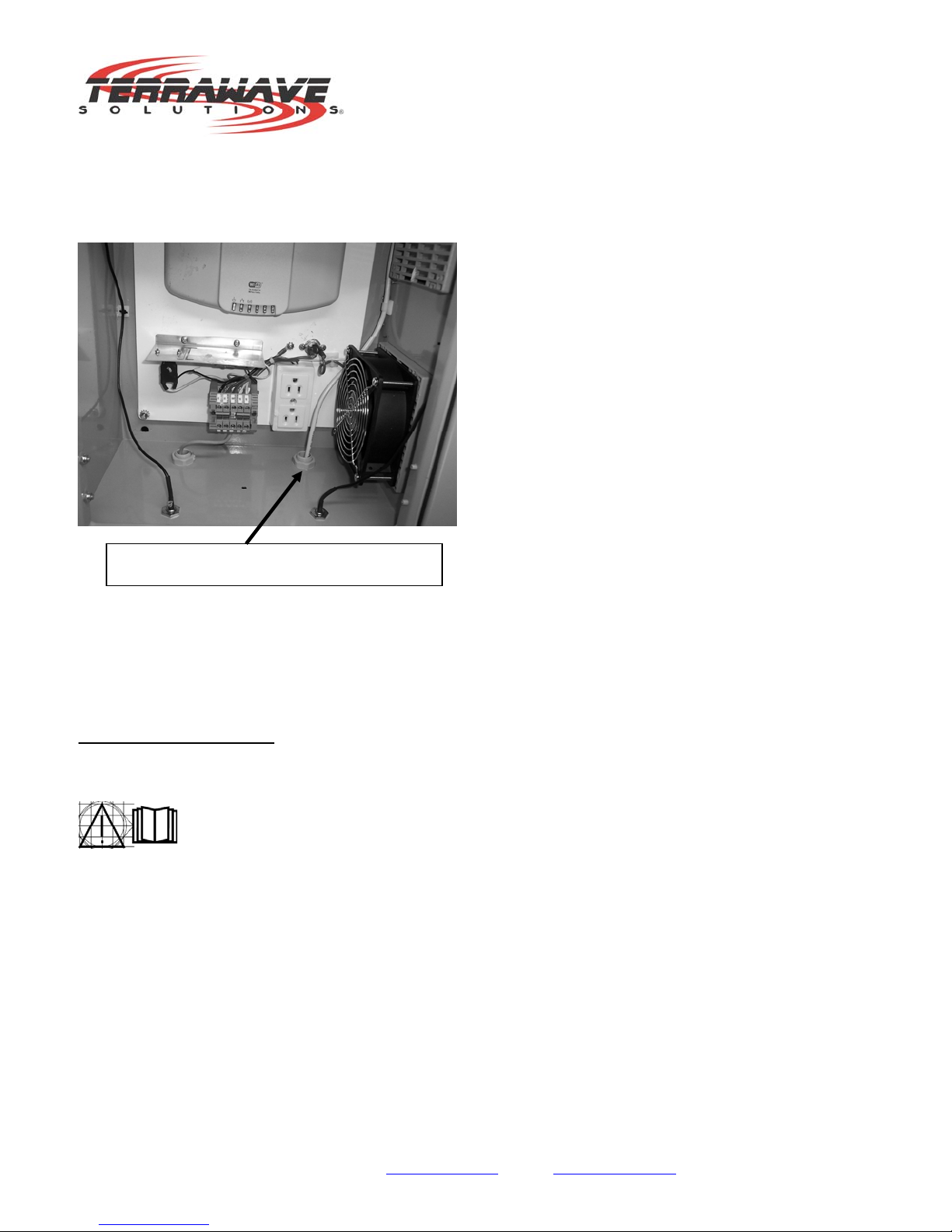
Always mount the enclosure with the cord gland facing down (figure 6). Failure to do so
could result in the unit filling with water – this could result in a hazardous condition and failure
of the unit.
(Figure 6)
WARNING: To prevent the risk of electric shock and equipment damage, disconnect any and
all power supplies to the enclosure before installing, maintaining or trouble shooting this
product or any products inside the enclosure.
Included Components
The TWSD16128PHC consists of the following components:
NEMA 4 Plug
Cooling Thermostat
Heating Thermostat
Heater
Cooling Fan
Mounting plate
Power socket
Terminal Block
Cord Gland
Cable Tie Downs
Cord Gland should face down to ground
10521 Gulfdale, San Antonio, TX 78216 I www.terrawave.com I Email: sales@terrawave.com I Phone: 210-375-8482
Version 1.1 - Page 5
Customer will be required to install Conduit for Ethernet. Conduit should be suitable for
environment used and wet applications.
Customer Supplied Items
Customers are required to provide their own mounting hardware. TerraWave recommends
3/8 inch fasteners, washers, lock washers and nuts. See figure 2.
Installing WLAN / Networking Components
The TWSD16128PHC will accommodate WLAN / Networking products to be installed inside
the unit. This equipment should be installed on the mounting plate in the unit.
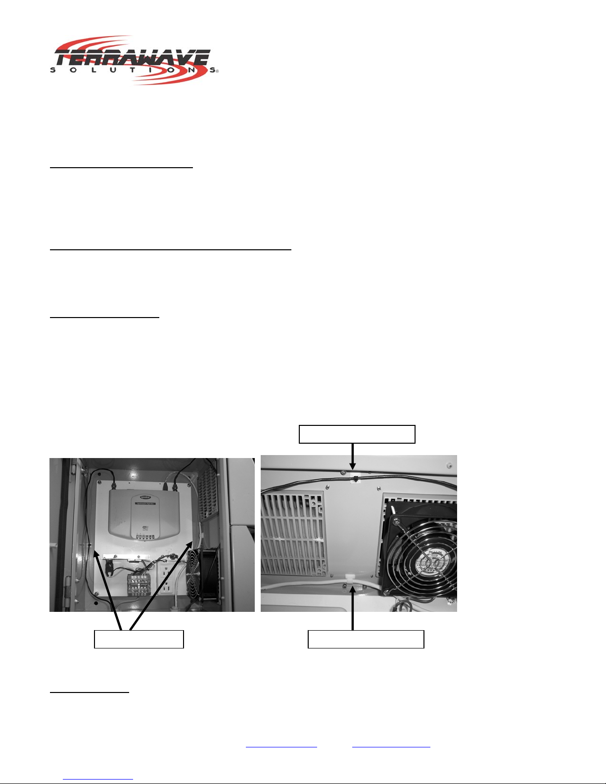
Wire / Cable Routing
The TWSD16128PHC comes with cable routing tie downs. These tie downs are used to
provide convenient cable routing. It is important to use these cable tie downs to ensure that
the cables that you install are kept away from the other components within the enclosure.
Refer to figure 3 below to illustrate the use of these tie downs.
(Figure 3)
Ethernet Cable
Cable tie Downs Ethernet Cable tie down
Coaxial Cable tie down
10521 Gulfdale, San Antonio, TX 78216 I www.terrawave.com I Email: sales@terrawave.com I Phone: 210-375-8482
Version 1.1 - Page 6
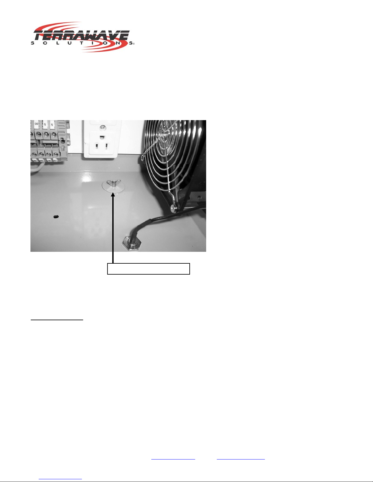
When installing Ethernet cabling into the TWSD16128PHC, you must remove the pre-
installed NEMA 4 plug in the bottom of the enclosure. To remove the plug, simply loosen the
fly nut located inside the unit. Once the Fly nut has been removed, the plug will fall out of the
enclosure. Replace the plug with conduit. The conduit must be suitable for environmental
and wet locations. Refer the NEC and follow any national or local codes. Refer to figure 4
below.
(Figure 4)
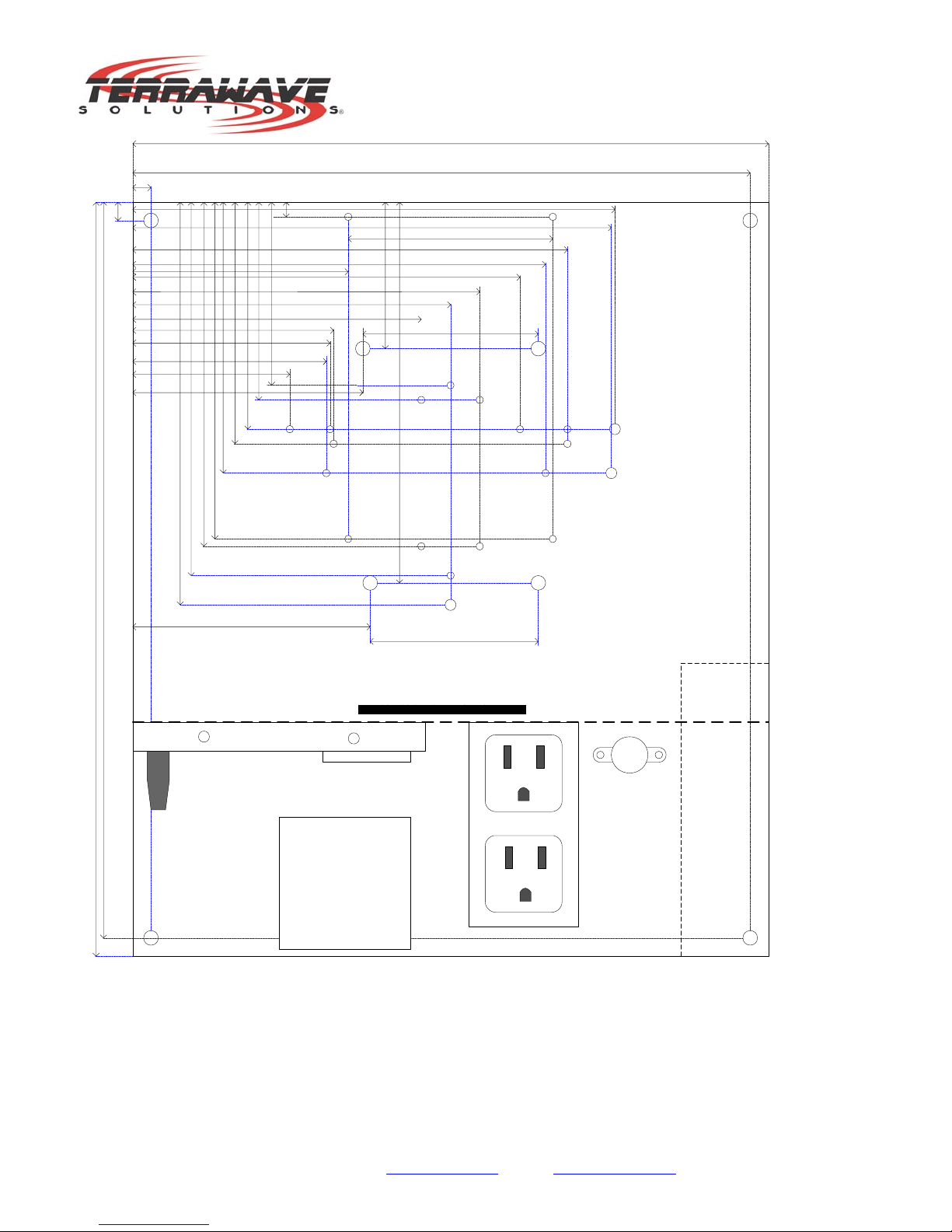
Mounting Plate
The TWSD16128PHC is supplied with a mounting plate to be used for attaching WLAN /
Networking components. The following diagram (figure 1) shows which holes should be used
when attaching approved products to the plate.
N
EMA 4 Plu
g
with Fl
y
Nu
t
10521 Gulfdale, San Antonio, TX 78216 I www.terrawave.com I Email: sales@terrawave.com I Phone: 210-375-8482
Version 1.1 - Page 7
A
A A
A
10.875"
12.875"
10.563"
0.313
12.563" 0.313"
Terminal Block
C
D
D
BB
C
BB
I
IE
F
G
HH
JJ
JJ
D D
Nothing higher than 4" from bottom
0.25"
3.125"
3.375" 3.875"
4.125" 4.625"
5.75" 5.875"
6.375" 6.875"
2.687"3.312"
3.375"
3.437"
3.687"
4.937" 5.437" 5.937" 6.625"
7.062"
7.437"
3.50" 8.187"
8.25"
A A
A A
2.50"
3.00"
6.50"
2.875"
3.938"
4.063"
Heater
Fan Space
Wires In
Wires Out
(Figure 1)

10521 Gulfdale, San Antonio, TX 78216 I www.terrawave.com I Email: sales@terrawave.com I Phone: 210-375-8482
Version 1.1 - Page 8
Hole Size Chart
Hole Size & Thread
A = 7/32” through hole – not threaded
B, C, D, I, J = 8-32 threaded hole
E, F, G = 10-32 threaded hole
H = 6-32 threaded hole
Hole usage ledger
Hole Used for
A Mounting holes to mate up with 10-32 thread x 2” standoffs
B Cisco 350 Metal Case
C & F Cisco 340 & 350 Plastic Case (F is for 10-32 locking post)
D Cisco 1200 and 3Com 8250
I & E Proxim AP (I is for 10-32 locking post)
J Cisco 1130 AP
H & G Symbol 4131 (G is for 10-32 locking post)
Customer Provided WLAN/Networking Mounting Screws
Qty Description
4 10-32 x 3/8” counter sunk – Philips head
4 8-32 x 3/8” round Philips head
2 6-32 x 3/8” round Philips head
1 10-32 locking post (TerraWave has sample)
3 8-32 x 3/8” flat head Philips head
Enclosure Mounting Holes
Mounting holes have been provided in the back of the enclosure. These holes provide easy
and convenient mounting of the unit.
Hole Plugs
The enclosure is supplied with pre-installed hole plugs which have been inserted into the
mounting holes. These plugs will need to be removed before mounting the unit. The plugs
are easily removed by squeezing the lock clips on the inside of the unit. Once the lock clips
of been pushed in, the hole plugs will easily slide out of the enclosure. Refer to figure 2.

10521 Gulfdale, San Antonio, TX 78216 I www.terrawave.com I Email: sales@terrawave.com I Phone: 210-375-8482
Version 1.1 - Page 9
Attachment
Attach the enclosure to a wall or other structure using customer supplied 3/8 inch fasteners,
flat washers and nuts. To insure that the unit maintains proper sealing it is very important to
make sure that the fasteners, washer and nuts are tightened thoroughly.
Note: Loose fasteners, washers and nuts may not provide proper sealing and /or securing of
the unit.
(Figure 2)
Mounting Holes / Plugs
Mounting Holes / Plugs

10521 Gulfdale, San Antonio, TX 78216 I www.terrawave.com I Email: sales@terrawave.com I Phone: 210-375-8482
Version 1.1 - Page 10
Electrical Wiring
NOTE
All electrical connections should be made by a licensed electrician. All local and National
codes should be followed as applicable.
Circuit Requirements
The TWSD16128PHC should be connected to a 120V, 15A feeder circuit.
The maximum capacity of the power receptacle in the unit is 120V, 12A.
The circuit breaker of the feeder circuit is considered to be the disconnect device for
TWSD16128PHC. Therefore, this circuit breaker should be readily accessible.
The strain relief (liquid tight cord connector) is suitable for flexible cord with a diameter of
10mm. We recommend using S-W or S-J cord, minimum 16 AWG.
WARNING – TO REDUCE THE RISK OF ELECTRIC SHOCK, DISCONNECT SUPPLY
MAINS BEFORE SERVICING.
The supply line used to feed power to the feeder circuit should be rated for outdoor use.
Refer to the NEC and local codes as applicable.
WARNING: To prevent the risk of electric shock and equipment damage, disconnect any
and all power supply to the enclosure before installing, maintaining or trouble shooting this
product or any products inside the enclosure.
Electrical Connection
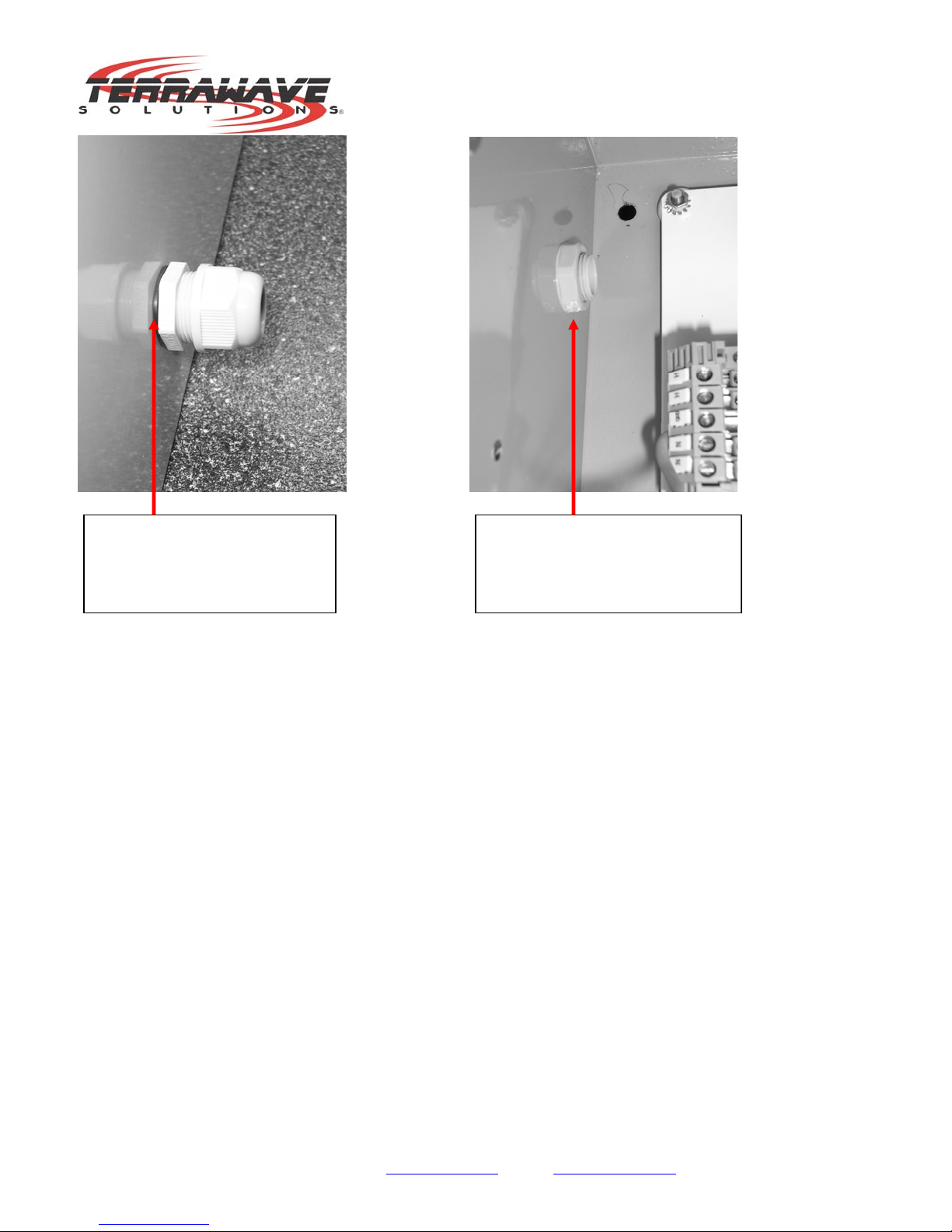
Before running electrical power to the device, you must first install the cord gland bushing
that comes included with the enclosure. Be sure the install the cord gland bushing with the
gasket of the outside of the enclosure. Also, the cord gland bushing nut should be tightened
snugly by hand. Once the bushing has been tightened by hand then use a wrench to apply
an additional quarter turn for final tightening. Do not over tighten the nut – over tightening the
nut can result in the cracking of the cord gland bushing. Refer to figure 8.
The electrical wiring should be routed through the cord gland bushing to the terminal block.
Refer to wiring diagram – figure 5.
10521 Gulfdale, San Antonio, TX 78216 I www.terrawave.com I Email: sales@terrawave.com I Phone: 210-375-8482
Version 1.1 - Page 11
Figure 8
Cord Gland Bushing nut on
inside of enclosure.
DO NOT OVER TIGHTEN!
Cord Gland Bushing on outside
of enclosure. Ensure that gasket
(black) is on outside of enclosure
when installing

10521 Gulfdale, San Antonio, TX 78216 I www.terrawave.com I Email: sales@terrawave.com I Phone: 210-375-8482
Version 1.1 - Page 12
Running Power to the unit
(Figure 5)
Note that all cables need to be rated for outdoor use and wet environments. Refer to the
NEC and local codes as applicable.
Figure 5 represents the terminal block and power leads that are wired to the terminal block
inside the TWSD16128PHC.
The wiring should be applied as follows:
1.) The Black wire in figure 5 represents the hot lead and should be attached to the terminal
block that is labeled ‘H’.
2.) The Green wire in figure 5 represents the Ground connection. The ground lead should be
attached to the terminal block that is labeled ‘GND’.
3.) The Gray wire in figure 5 represents the neutral. The neutral wire should be attached to
the terminal block labeled ‘N’.
Legend
H– Hot lead
GND – Ground
N– Neutral
This manual suits for next models
1
Table of contents
Popular Enclosure manuals by other brands

Fractal design
Fractal design DEFINE C user guide

swiftech
swiftech quiet power FS20-H20 series installation guide

Akasa
Akasa integral HDD external enclosure for data-storage mobility with LAN... user manual

SilverStone
SilverStone SST-PS06B manual

Pulsar
Pulsar AWO529 installation instructions

Sharkoon
Sharkoon Quickstore Portable manual


Altronix
Altronix Trove T3MK75F16 installation guide

Sharkoon
Sharkoon REBEL C60 manual

Dot Hill Systems
Dot Hill Systems AssuredSAN 3004 Series Setup guide

Western Digital
Western Digital WDBABV0010ABK - Elements SE Portable user manual

Positron
Positron BRX-XLR-2 quick start guide

Icy Dock
Icy Dock MB662U3-2S user manual